 Open Access Article
 This Open Access Article is licensed under a
 Creative Commons Attribution 3.0 Unported Licence
Computational screening of structural and compositional factors for electrically conductive coordination polymers†
Davide
Tiana
a,
Christopher H.
Hendon
a,
Aron
Walsh
*a and
Thomas P.
Vaid
*b
aDepartment of Chemistry, University of Bath, Claverton Down, Bath BA2 7AY, UK. E-mail: a.walsh@bath.ac.uk
bDepartment of Chemistry, The University of Alabama, Tuscaloosa, Alabama 35487, USA. E-mail: tpvaid@ua.edu
First published on 14th February 2014
Abstract
The combination of organic and inorganic chemical building blocks to form metal–organic frameworks (MOFs) offers opportunities for producing functional materials suitable for energy generation, storage and conversion. However, such applications rely on robust electron transport and the design of conductive hybrid materials is still in its infancy. Here we apply density functional theory to assess the important structural and compositional factors for forming conducting MOFs. We focus on 1D metal–organic polymers as a model system and assess the choice of organic, inorganic and linking units. The results demonstrate that electronic communication is sensitive to the energy and symmetry of the frontier orbitals associated with the organic and inorganic building blocks and offers guidance on how to optimise electrical conduction in hybrid materials.
1. Introduction
Metal–organic frameworks (MOFs) are crystalline materials that consist of metal atoms or clusters linked by polydentate organic ligands to form extended networks, and they now constitute a very large class of materials, with thousands of reported examples.1–4 The term MOF is often (but not always) taken to imply that the material is porous,5 but we will use the term herein to refer to all hybrid organic–inorganic frameworks and coordination polymers, whether porous or not. Most of the research on MOFs has examined applications that require porosity, such as gas storage6 or sensing,7 and that may be due, in part, to the fact that the vast majority of MOFs are electrically and magnetically uninteresting (i.e., they are electrical insulators and either diamagnetic or paramagnetic). For example, the prototypical MOF, MOF-5, has a measured8 and calculated9 band gap of about 3.5 eV, and some nickel–pyrazolate MOFs have calculated band gaps of 3.3–3.4 eV.10 An electrically conducting porous MOF would have a greatly expanded range of possible applications, as, for instance, high-capacity electrodes for supercapacitors or batteries, size-selective electrodes for electrocatalysis, or gas sensor materials with an easily transduced signal (electrical resistance). Even non-porous electrically conducting MOFs are of interest, since their physical properties (e.g. electronic band gap) are tunable through changes in the structure and composition of the organic bridging ligand, while the physical properties of traditional inorganic semiconductors are not tunable in that way.11,12 At the same time, MOFs have an extended ordered network of covalent bonds, and a semiconducting MOF is therefore likely to have higher carrier mobility than an organic semiconductor, which relies upon intermolecular electron transfer for charge movement. MOFs are now beginning to be incorporated in electronic devices, but primarily as passive, electrically insulating scaffolds.13While the search for electrically conducting MOFs is an active area of research, only a few scattered examples have been reported. The ligand pyrazine-2,3-dithiolate (pdt) forms square planar coordination complexes with copper and Ni, [Cu(pdt)2]− and [Ni(pdt)2]−, which react with CuI to form the framework materials Cu[Cu(pdt)2] and Cu[Ni(pdt)2],14,15 respectively, both of which are semiconductors. Ni and pyrimidine-2-thiolate form a two-dimensional network [Ni(C4N2H3S)2]n that is semiconducting.16 A somewhat related compound is formed between silver and pyridine-2-thiolate, [Ag(C5NH4S)]n, which is also semiconducting, but it is possible that the conductivity in that case is due to direct Ag–Ag interactions.17 The silver salt of the dianion of cyanuric acid, [Ag2C3N3O3H]n, adopts a three-dimensional network structure that includes two-dimensional silver sheets with particularly short Ag–Ag contacts.18 [Ag2C3N3O3H]n is semiconducting, and in this case the conductivity cannot be due solely to Ag–Ag interactions, as it is conducting both parallel and perpendicular to the Ag sheets. Ni forms one-dimensional coordination polymers with both 6-mercaptopurine and 6-thioguanine, and both of them are semiconducting.19 Hybrid networks containing Cu+, Cu2+, or Ag+ and 1,4-benzenedithiolate20 or Fe2+, Ni2+, or Cu2+ and 1,2,4,5-benzenetetrathiolate21 are semiconducting, but none of those materials are crystalline, and were not structurally characterized. Several networks or polymers containing Ni2+ and C2S42−, C4S42−, C4S62−, C4S82−, C6H2S42−, or C6S82− are semiconducting, but they are also all amorphous.22–26 The compound formed between Pb2+ and benzenehexathiolate, [Pb3(C6S6)]n, is crystalline with a three-dimensional network structure and is semiconducting.27,28 Several conjugated organic systems containing multiple cyano groups (tetracyanoethylene, TCNE; 7,7,8,8-tetracyanoquinodimethane, TCNQ; 1,2,4,5-tetracyanobenzene, TCNB; N,N′-dicyanoquinonediimine DCNQI) have been used to form networks with various metal ions, and several of those are electrically conducting.29–34 Most recently, Yaghi and co-workers have reported two porous conducting MOFs, one containing copper and hexahydroxytriphenylene35 and the other iron and 1,2,3-triazole.36
Other crystalline, electrically conducting materials containing both organic and inorganic components are known, but do not fulfil all of the criteria for the MOFs we are considering herein. For example, an intriguing set of compounds are known that contain one-dimensional chains or two-dimensional sheets of II–VI semiconductors such as ZnTe or CdSe with diamine ligands such as 1,3-propanediamine (pda) that chelate each metal atom along the one-dimensional inorganic chains in ZnTe(pda), or the diamine ligand bridges between two-dimensional inorganic sheets as in CdSe(pda)0.5.37 In those materials the organic component is electrically insulating and serves mainly a structural role; in a conducting MOF the organic “struts” must have a conjugated π-system that can, in principle, support electronic communication between the inorganic “nodes.” In a recent report tetrathiafulvalene-tetrabenzoate (H4TTFTB) was used to synthesize the porous MOF Zn2(TTFTB), in which TTF moieties are held in a helical stack with a closest S⋯S contact of 3.803(2) Å.38 While Zn2(TTFTB) has low bulk powder conductivity, it has a reasonable carrier mobility of 0.2 cm2 V−1·s−1, almost certainly along the TTF stacks. In Zn2(TTFTB) the organic component is conducting and the inorganic (Zn-carboxylate) component is insulating, essentially the inverse of the situation in the CdSe(pda)0.5-type materials. We hope to discover organic struts and inorganic nodes that can be combined to form MOFs wherein the carrier mobility is high through the entire inorganic–organic system, so that when the inorganic and organic components do not form individual continuous networks (as they do not in a typical porous MOF such as MOF-539), electrical conductivity is still possible.
While there are a few examples of (usually non-porous) conducting MOFs, as described above, there is not yet a set of general design principles for the creation of conducting MOFs. The goal of this paper is to provide such a set of principles to lend some guidance for future efforts toward the synthesis of conducting MOFs. We have calculated the electronic structure of a range of model compounds, based on a first-principles density functional theory (DFT) approach, to examine how changes in composition (identity of the metal atom, identity of the atom linking the metal to the organic component) and several other factors (size of the organic π-system, oxidation state of the metal and/or organic system, the presence of heteroatoms within the organic system) affect the predicted electronic structure of the material. We have used one-dimensional polymers as a model, since it is challenging to predict the full three-dimensional structure that will be adopted by a given metal and bridging ligand. The reduction to one dimension also greatly simplifies the analysis of the band structure, as only one dimension in reciprocal space is relevant and all inter-chain interactions are excluded. The trends discovered in our study are expected to provide a solid foundation for understanding the behaviour of analogous two- and three-dimensional frameworks.
2. Computational details
All calculations were performed using the Quantum Espresso package (version 4.3.2)40 within the Kohn–Sham DFT formalism. The PW91 exchange–correlation functional41,42 was employed using ultra-soft pseudopotentials for the core electrons.43 The electronic structure was optimised at a non-collinear level of theory with the inclusion of spin orbit coupling. For the open-shell transition metals, the spin moment was fully optimised in each case without constraint of the total spin. The kinetic energy wave-function cut-off for the plane-wave basis set was fixed at 45 Ry, whereas the charge density cut-off was set to 450 Ry (see the ESI† for details on the cut-off converge). During the geometry optimization, the k-points were generated using a Monkhorst–Pack grid44 of 16 × 2 × 2, with (100) being the repeat direction of the polymer. The Marzari–Vanderbirt smearing occupation was used with a value of 0.04 degauss.45 At this level of theory, the structures and chemical bonding are well described; however, for band gaps we will focus only on qualitative trends as quantitative predictions require the application of appropriate excited-state techniques.The geometry of all the polymers was optimized with the following steps. First, a single molecule was optimized using the universal force field46 included in the code Avogadro.47 The 1D polymer was then built by applying periodic boundary conditions to the optimized molecule in an orthorhombic unit cell, with a the polymer repeat direction. The cell vector a therefore equals the monomer length, while the b and c vectors were fixed with a length such that there was a minimum distance of 8 Å between neighbouring chains (all cell parameters are reported in the ESI†). The internal atomic positions as well as the length of cell vector a were then relaxed until convergence in the forces was achieved to within 0.001 eV per Å.
3. Results and discussion
(a) Prototype Ni polymers
The series of aromatic polymers examined have the chemical formula Na2[Ni(CxHyS4)]n, where the hydrocarbon core of the ligand is ethylene, benzene, naphthalene, anthracene, tetracene, or pentacene, the first three of which are shown in Fig. 1. The Na+ ions are present in this series to set a charge of 4− on the CxHyS4 ligands and maintain the aromaticity of their organic cores. The oxidation state of the ligands in this series is different from the known conducting polymers just mentioned; polymers with tetrathiolate ligands with a charge of 2− will be discussed later.
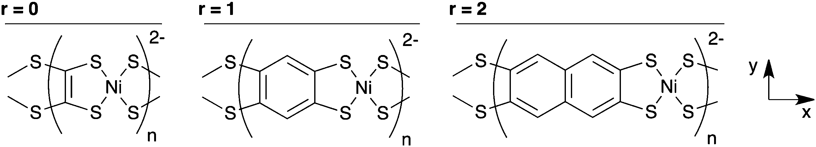 | ||
| Fig. 1 Three of the Na2n[Ni(CxHyS4)]n polymers studied, with the axis system used throughout this paper. Na+ counterions are omitted for clarity. | ||
We first calculated the molecular orbitals (MOs) of the isolated neutral tetrathiol ligands (ethylenetetrathiol, 1,2,4,5-benzenetetrathiol, etc.) so that we could examine the orbitals on the ligand that will interact with Ni. Images of the highest occupied molecular orbital (HOMO), lowest unoccupied molecular orbital (LUMO), and the MO immediately lower in energy than the HOMO (i.e., HOMO − 1) for each molecule are shown in Fig. 2, while Fig. 3 shows the energies of several MOs for each molecule. For all of the organothiol ligands, the S atoms have pz orbitals that are a significant component of the HOMO − 1, HOMO, and LUMO, and these S pz orbitals will interact with the Ni atoms in the polymers. The relative phase of the two S pz orbitals on the same side (right or left) of the ligand will determine which of the Ni d orbitals are of the proper symmetry for interaction when Ni is coordinated by a square planar arrangement of S atoms in the polymer. When the S pz orbitals are of the same phase, then the Ni dxz orbitals (see Fig. 1 for the axis system) will interact. When the S pz orbitals are of the opposite phase to each other, then the Ni dyz orbitals will interact. The Ni dz2, dxy, and dx2−y2 orbitals are expected to have no net interaction with the S pz orbitals in either case.
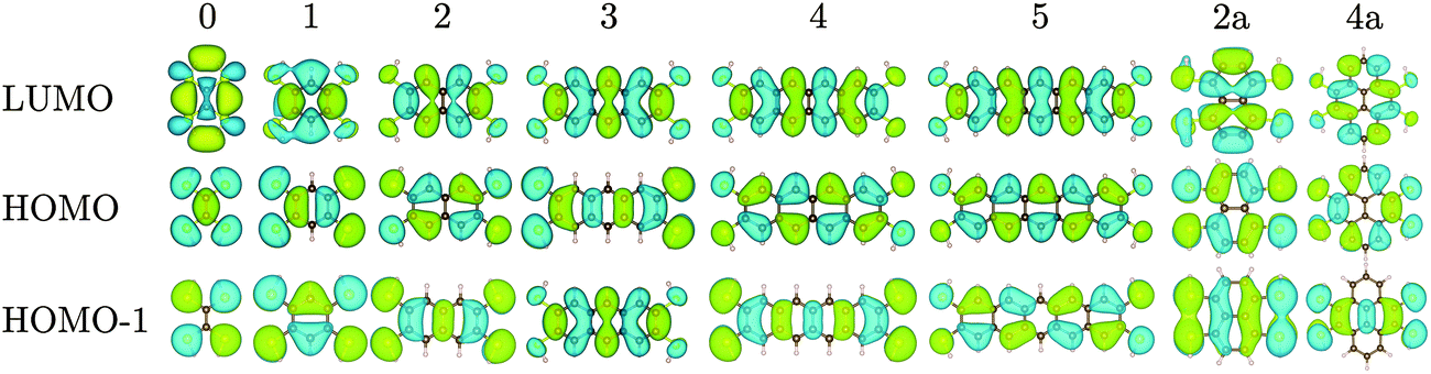 | ||
| Fig. 2 Molecular orbitals of ethylenetetrathiol, 1,2,4,5-benzenetetrathiol, 2,3,6,7-naphthalenetetrathiol, etc., with the number of rings (r) indicated above each set of orbitals. Atoms colour: C = brown, S = yellow, H = beige. | ||
 | ||
| Fig. 3 Molecular orbital energies for the tetrathiol ligands of Fig. 2. The black lines denote HOMOs and LUMOs. The vacuum level is set to 0 eV. | ||
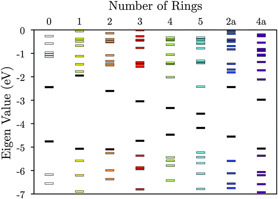
Many of the tetrathiol ligand MOs are observed, almost unaltered, in the electron density distributions of the Na2n[Ni(CxHyS4)]n bands, as shown in Fig. 4 (all the electron distributions in Fig. 4 are at the Γ point in reciprocal space). A summary of the band gaps and highest occupied crystal orbital (HOCO) and lowest-unoccupied crystal orbital (LUCO) band dispersions are given in Table 1. For the ethylene core (r = 0, for zero fused rings), the S pz orbitals of the ligand interacts with the Ni dxz atomic orbital to form the extended HOCO of the polymer. The polymer LUCO is a ligand-field state that comprises mainly the Ni dxy atomic orbital. The LUCO band dispersion is due to interactions of the directed S atomic orbitals across the ethylenetetrathiolate bridge. The HOCO − 1 is formed by a non-bonding Ni dz2 orbital.
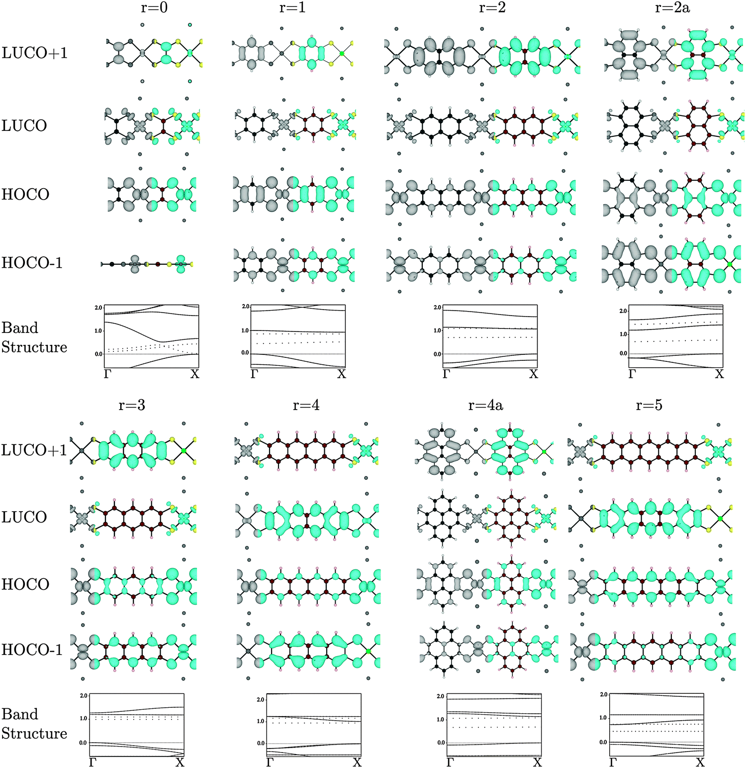 | ||
| Fig. 4 Electron distribution (at the Γ point) of the HOCO − 1, HOCO, LUCO, and LUCO + 1, and band structures of the Na2[Ni(CxSy)]n polymers. The top of the valence band is set to 0, the band energies are in eV, and the Na contribution to the band structures are drawn as dotted lines. Atoms colour: Ni = bright green, C = brown, S = yellow, H = beige, Na = dark grey. | ||
| Organic component | r | E g (eV) | HOCO dispersion | LUCO dispersion | E g classification |
|---|---|---|---|---|---|
| Ethylene | 0 | 1.45 | 0.78 | 0.72 | D |
| Benzene | 1 | 1.01 | 0.55 | 0.07 | I |
| Naphthalene | 2 | 1.10 | 0.39 | 0.04 | D |
| Anthracene | 3 | 1.20 | 0.29 | 0.02 | I |
| Tetracene | 4 | 1.02 | 0.22 | 0.22 | D |
| Pentacene | 5 | 0.46 | 0.15 | 0.30 | D |
| Naphthalene, side-on | 2a | 1.19 | 0.43 | 0.22 | I |
| Pyrene | 4a | 1.15 | 0.09 | 0.13 | D |
For the benzene core (r = 1), the HOMO of the ligand again interacts with the Ni dxz to form the extended HOCO of the polymer, but due to the orbital symmetry the valence band maximum (antibonding interaction) is at the Γ point. The HOMO − 1 of the ligand combines with the Ni dyz to form the extended HOCO − 1 of the polymer. The polymer LUCO is a ligand-field state that comprises mainly the Ni dxy atomic orbital; this leads to a flat LUCO band, with a calculated dispersion of only 0.07 eV. The LUCO + 1 band is simply the ligand LUMO.
For r = 2 (the naphthalene core), the tetrathiol LUMO and a small component of the Ni dxz combine to form the LUCO + 1. The polymer LUCO is a ligand-field state that comprises mainly the Ni dxy atomic orbital; this leads to a very flat LUCO band, with a calculated dispersion of only 0.04 eV. Again, the HOCO and HOCO − 1 states are formed of combination of the Ni dxy and dyz orbitals, respectively. For r = 2a (the naphthalene core with Ss attached to different carbon atoms, so that the naphthalene core is rotated by 90°), the polymer HOCO − 1 is simply the ligand HOMO, while the polymer HOCO is formed from the combination of the ligand HOMO − 1 with the Ni dxz. The LUCO is the Ni dxy atomic orbital, while the LUCO + 1 is the combination of the ligand LUMO and the Ni dyz.
For r = 3 (the anthracene core) the polymer HOCO is formed from the combination of the ligand HOMO with the Ni dxz. The LUCO is the Ni dxy ligand-field state, while the LUCO + 1 is the ligand LUMO. For r = 4 (the tetracene core) the polymer HOCO − 1 is the ligand HOMO. The polymer HOCO is the combination of the Ni dxz and the ligand HOMO − 2 (not shown in Fig. 2). The LUCO is the combination of the ligand LUMO and a small contribution from the Ni dxz, while the LUCO + 1 is the Ni dxy ligand-field state. For r = 4a (the pyrene core) the polymer HOCO is the combination of the ligand HOMO and Ni dxz, while the LUCO is the Ni dxy ligand-field state and the LUCO + 1 is the ligand LUMO. For r = 5 (the pentacene core) the polymer HOCO is the combination of the ligand HOMO and Ni dyz. The LUCO is the ligand LUMO, while the LUCO + 1 is the Ni dxy ligand-field state.
In the series r = 1−5 there is an important change that occurs between r = 3 and r = 4. For r = 1, 2, and 3 the LUCO is comprised of the antibonding combination of Ni dxy orbital and four in-plane S p-orbitals directed toward Ni, which form a flat, localized band. The LUCO + 1 consists of the ligand LUMO state of Fig. 2. As the number of fused rings increases, the energy of the ligand LUMO decreases, such that for r = 4 and 5 it is the polymer LUCO. Such a transition could result in an abrupt change from band to hopping conductivity.
| Linker | Organic ligand | E g (eV) | HOCO dispersion | LUCO dispersion | E g classification |
|---|---|---|---|---|---|
| O | Benzene | 0.72 | 0.76 | 0.05 | D |
| S | Benzene | 1.01 | 0.55 | 0.07 | I |
| Se | Benzene | 1.01 | 0.41 | 0.02 | I |
| O | Pentacene | 0.90 | 0.16 | 0.00 | D |
| S | Pentacene | 0.74 | 0.15 | 0.20 | D |
| Se | Pentacene | 0.74 | 0.14 | 0.16 | D |
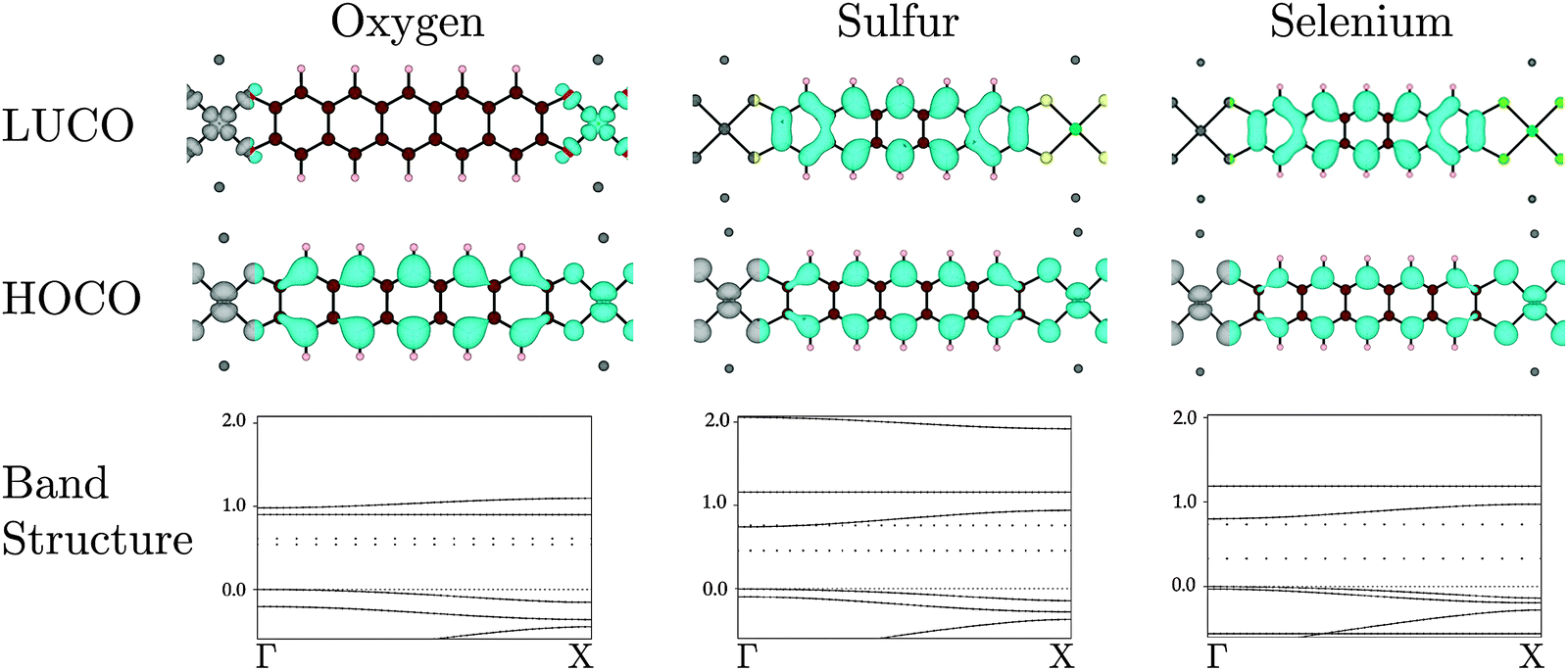 | ||
| Fig. 5 Electron distribution (at the Γ point) of the HOCO, LUCO and band structures for oxygen, S and Se bridging substituents, respectively. The band energies are given in eV. The Na contribution to the band structures are drawn as dotted lines. Atoms colour: Ni = bright green, C = brown, S = yellow, H = beige, O = red, Se = pea green, Na = dark grey. | ||
When oxygen is the connecting element, in Na2n[Ni(C22H10O4)]n, the identity of the polymer LUCO is different from that in the S and Se versions. As can be seen in Fig. 5, the Na2n[Ni(C22H10O4)]n LUCO is a local Ni dxy ligand field state. This localized state gives essentially no band dispersion. The same ligand field state is visible in the band diagrams of Na2n[Ni(C22H10S4)]n and Na2n[Ni(C22H10Se4)]n in Fig. 5, where it is the flat LUCO + 1 band. The greater electronegativity of oxygen places this band at lower energy in Na2n[Ni(C22H10O4)]n, where it becomes the LUCO.
In the set of compounds in which benzene is the organic core, the polymer HOCO results from interaction of the Ni dxz and the ligand HOMO in all cases (O, S, and Se). The HOCO dispersions (see Table 2) are significantly larger than for the pentacene-based polymer, and largest with oxygen as the linking atom. The LUCO is the Ni dxy ligand field state for all linking elements, and all of the LUCO bands therefore have low dispersion.
The implication of these results in the synthesis of conducting MOFs depends partly upon the identity of the organic core of the ligand. For all linking atoms and both organic cores, the HOCO had some dispersion, which implies that with appropriate oxidative doping all would be reasonable p-type conductors. With a small conjugated organic system (represented by benzene here), the LUCO is always a ligand field state, so it is unlikely that good n-type conductivity can be achieved. With a larger conjugated organic system (represented by pentacene here), with S or Se as the linking atom a LUCO with band dispersion results. With appropriate reductive doping an n-type conductor could be obtained. In fact, for the pentacene core and S or Se linking atoms, the band gap is less than 1 eV and hence intrinsic conductivity is possible.
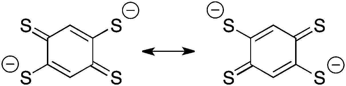 | ||
| Fig. 6 Benzene-1,2,4,5-tetrathiolate in the 2− (quinoid) oxidation state. | ||
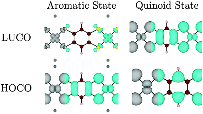 | ||
| Fig. 7 Electron distribution (at the Γ point) of the HOCO, LUCO for Na2n[Ni(C6H2S4)]n (left) and [Ni(C6H2S4)]n (right). Note that the HOCO of the aromatic state becomes the LUCO of the oxidized quinoid state. Atoms colour: Ni = bright green, C = brown, S = yellow, H = beige, Na = dark grey. | ||
A structural distortion might naively be expected in the oxidized polymers to facilitate localization of the ligand π-bonds; such bond-length alternation does occur in undoped polyacetylene.48 However, in all of the optimized [Ni(CxHyS4)]n structures (from r = 1 to 5) no bond-length alternation occurred; even when an initial distortion was artificially imposed, the system returned to a symmetric structure upon optimization at this level of theory. A quasi-metallic state was found to check if this solution was due to the use of a semi-local exchange–correlation functional, the electronic structure of Na2[Ni(C6H2S4)]n and [Ni(C6H2S4)]n were also calculated using the inclusion of 25% non-local exact exchange. Indeed, the metallic behaviour is lost, and a small band gap of 0.43 eV is opened for the quinoid state. However, the orbital contributions to the HOCO and LUCO remain unchanged, and no bond alternation is observed.
Interestingly for this oxidised state, significant band dispersion is observed: both the Ni dyz and the dxz orbitals (the metal components of the HOCO and LUCO, respectively) have the appropriate symmetry to overlap with the organic ligand. This results in a dispersion of 0.29 eV (valence band) and 0.87 eV (conduction band). We can therefore conclude that quinoid systems are likely to have a small band gaps, high carrier mobility, and therefore high conductivity.
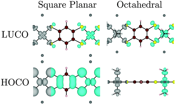 | ||
| Fig. 8 Electron distribution (at the Γ point) of the HOCO, LUCO for the Ni r = 1 polymer as a function of metal coordination environment. Note that while the LUCO remains unchanged, the additional of axial ligands changes the HOCO from Ni dxy to dz2. Where the metal dz2 orbital is present, a side-on view is used for clarity. Atoms colour: Ni = bright green, C = brown, S = yellow, H = beige, Na = dark grey, N = black spot. | ||
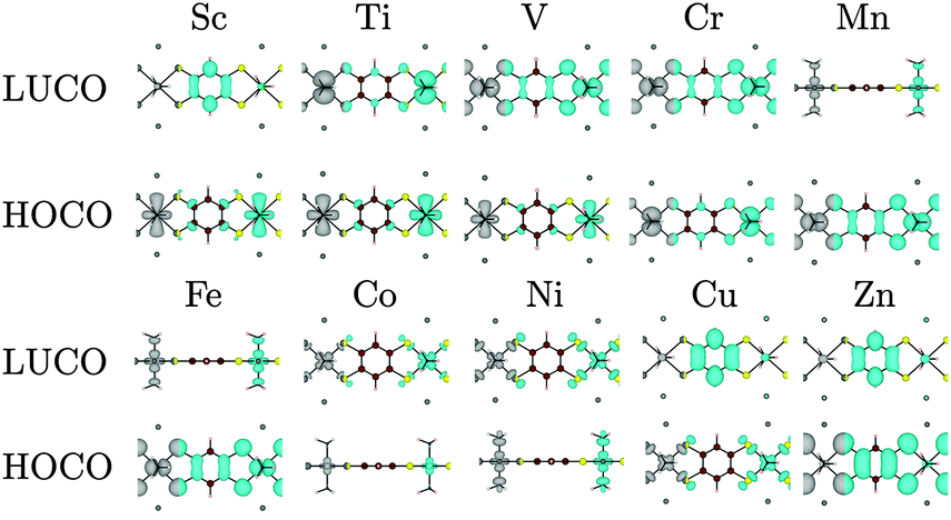 | ||
| Fig. 9 Electron distribution (at the Γ point) of the HOCO, LUCO as a function of the 3d metal, in octahedral coordination. The results for Sc, Ti, and V are included for completeness, but the oxidation states do not frequently occur in nature. Where the metal dz2 orbitals are present, a side-on view is used for clarity. Atoms colour: Ni = bright green, C = brown, S = yellow, H = beige, Na = dark grey, N = black spot. | ||
(b) Other archetype systems
The model polymers discussed above allowed a systematic investigation of specific chemical changes on the electronic structure. However, there are several reported organic–inorganic systems that are either semiconducting or were investigated for their possible electrical conductivity, but differ significantly from the structural motif explored above. Some of these were mentioned in the Introduction. The structural motifs can be projected onto one-dimensional polymers that are representative of the three-dimensional hybrid frameworks. This model approach allows for a direct comparison with the Ni polymers analysed in the previous section. The structures of the prototype systems are shown in Fig. 10 and a summary of their properties is given in Table 3.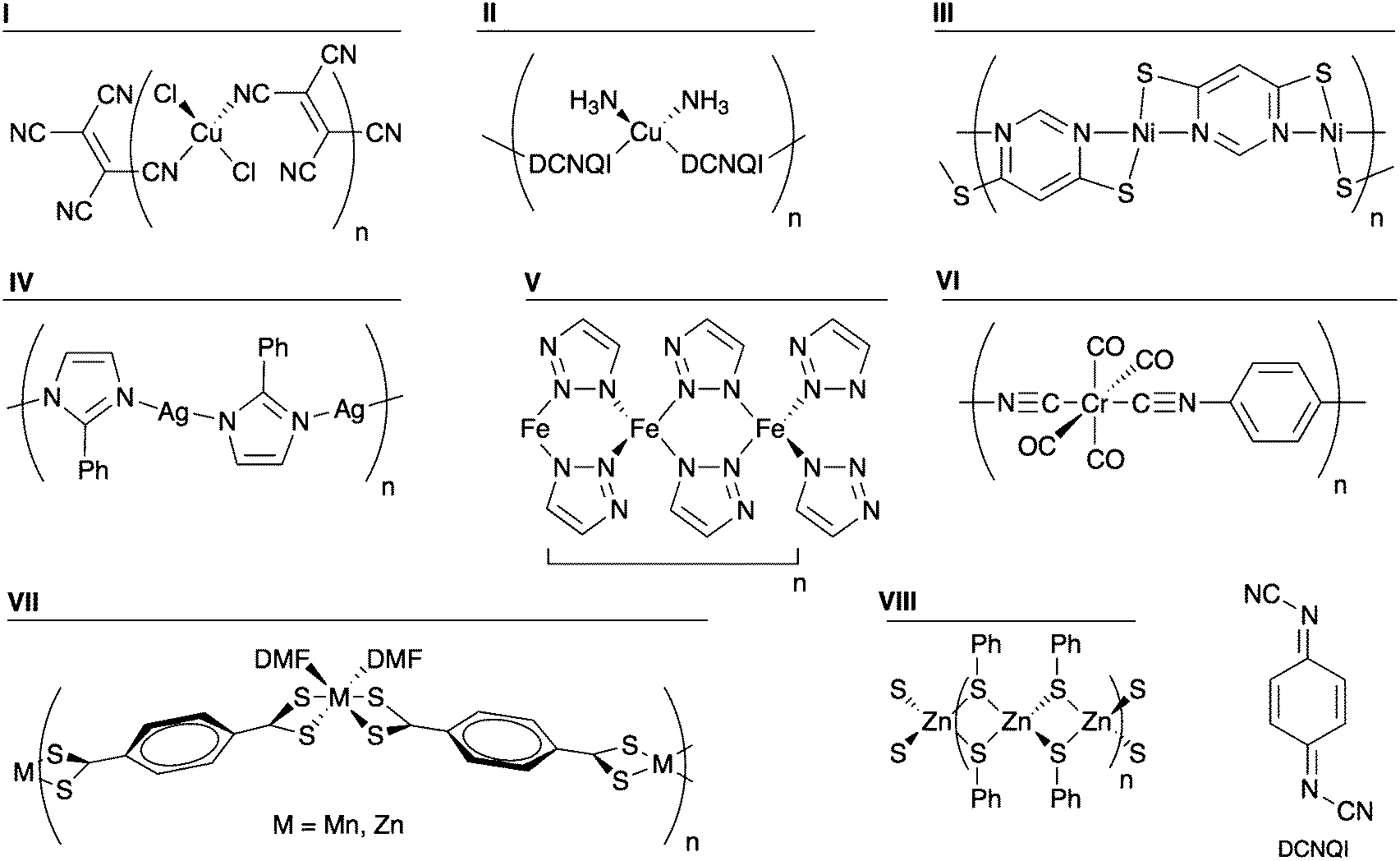 | ||
| Fig. 10 Structures of the archetypal organic–inorganic polymers examined. | ||
| Compound | Metal | Organic ligand | E g (eV) | HOCO dispersion | LUCO dispersion | E g classification |
|---|---|---|---|---|---|---|
| I | Cu | TCNE | 0.67 | 0.00 | 0.01 | D |
| II | Cu | DCNQI | 0.02 | 0.35 | 0.01 | D |
| III | Ni | Pyrimidine | 0.45 | 0.18 | 0.27 | D |
| IV | Ag | Imidazole | 3.21 | 0.06 | 0.06 | D |
| V | Fe | Triazole | 0.78 | 0.07 | 0.11 | D |
| VI | Cr | Cyanide | 1.87 | 0.31 | 0.67 | D |
| VII | Mn | TTPT | 0.02 | 0.02 | 0.02 | D |
| VII | Zn | TTPT | 1.34 | 0.00 | 0.04 | D |
| VIII | Zn | Thiolate | 1.43 | 0.29 | 0.26 | D |
Several organocyanide–metal networks exhibit electrical conductivity.29–34 Two model polymers were examined: [CuCl2(TCNE)]n (I in Fig. 10) and [Cu(DCNQI)]n (II in Fig. 10) (TCNE = tetracyanoethylene; DCNQI = N,N′-dicyanoquinonediimine). The latter is a metallic conductor at room temperature.30 When analysing I, we found a band gap of 0.67 eV, with the HOCO and the LUCO giving no significant dispersion. Indeed the HOCO is the Cu–Cl bond, while the LUCO consists of the ligand LUMO. We found polymer II to be semimetallic with a large dispersion, 0.35 eV, at the Fermi level. This dispersion is due to the overlap of the Cu dxz orbital with the N pz of the cyano group, which further conjugates with the aromatic ring, resulting in an infinite delocalisation along the chain. Thus we can see that the one-dimensional polymers capture the essential features of the band structure.
Another interesting class of hybrid material known to be semiconducting can be found combining heterocyclic thiolates with Cu, Ni, or Ag.14–17 A representative polymer consisting of Ni2+ and pyrimidine-4,6-dithiolate (compound III) was constructed and its band structure examined. The coordination sphere of Ni2+ is distorted square planar, with the structure shown in Fig. 10. Both the valence and conduction bands have dispersions of 0.18 and 0.27 eV, respectively. The origin of that band dispersion is the Ni dxz orbital overlap with S pz, forming the HOCO, whereas the LUCO is formed by the mixture of the Ni dx2−y2 and the N pz orbital of the pyrimidine. Furthermore, the calculated band gap is small, 0.45 eV. These numbers corroborate the electrical conductivity reported for several compounds of this type.
The coordination polymer of 2-phenylimidazole and silver (compound IV) has been analysed as an analogue of imidazolate frameworks.49 With a calculated band gap of 3.21 eV and negligible band dispersion, this class of system does not seem to be interesting from a band conduction perspective.
The recent report of a conducting MOF constructed from Fe2+ and 1,2,3-triazole led us to examine the one-dimensional polymer [Fe(C2H2N3)2]n (V).36 The moderate band gap (0.78 eV) and band dispersion is consistent with electrical conductivity. The band dispersion arises from metal–metal interactions (Fe⋯Fe distance 3.7 Å), which are possibly semiconducting, although they were not found to be electrically conductive.
An intriguing system that was investigated for its possible conductivity is the cubic network of Cr(1,4-diisocyanobenzene)3 reported by Yaghi and Choi in a patent.50 The polymer [Cr(CO)4(1,4-diisocyanobenzene)]n (VI) was examined as a model of that network. Although it has significant band dispersion, its calculated band gap of 1.87 eV is quite large.
Two one-dimensional polymers of tetrathioterephthalate have been reported, [M(S2CC6H4CS2)(DMF)2]n (M = Zn, Mn).51 While the Mn compound has a visible absorption onset at 925 nm, corresponding to 1.34 eV, no electrical conductivity was reported. We have calculated the electronic structure of both compounds (VII; M = Zn, Mn); both have negligible bands dispersion. In the case of Mn, the HOCO and LUCO are the dz2 and the dx2−y2, respectively. Such symmetry does not facilitate overlap with the frontier orbitals of the organic ligand. Regarding Zn, as seen in the previous section, the d shell is complete and does contribute to the frontier orbitals.
Finally, there is a class of compounds comprising clusters of transition metals (Fe, Co, Zn and Cd) linked into three-dimensional networks by bridging thiolates that have been reported as semiconducting materials.52–54 Polymer VIII, [Zn(SPh)2]n, was studied as a model system, and it is the only analysed case were a Zn compound showed significant band dispersion. However, the role of Zn is indirect: the band dispersion arises from S contacts through the metal centre (S⋯S distance = 3.4 Å). While the role of Zn appears to be structural in this case, it could be partially substituted (e.g. by Cu or Al) to enhance the semiconducting behaviour. In a recent example, some of the Zn2+ sites of MOF-5 were substituted by other transition metal ions, leading to electroactivity.55
4. Conclusions
From the series of Ni-based polymers studied here a number of conclusions can be drawn:(1) Excluding the tetracene and pentacene, the LUCOs of the polymer are localized ligand-field states. It is therefore likely that to obtain MOFs with good intrinsic or n-type conductivity, linkers with large conjugated π-systems (and therefore small HOMO–LUMO gaps) will be necessary. This does not rule out the possibility of creating good p-type conductors with the smaller linkers, but doping or other methods will be necessary to create significant carrier concentrations.
(2) Considering oxygen as the standard linking atom (in carboxylates), less electronegative species and “softer” linking atoms such as S or Se (rather than oxygen) generally decrease the band gap and increase the band dispersions of the polymers (and therefore analogous MOFs). However, the change from S to Se is quite small, and considering the greater synthetic difficulties involved with the use of Se, S may be preferred over Se.
(3) When the organic tetrathiolate linker is oxidized to the 2− oxidation state (quinoid), a polymer with a small band gap and larger band dispersions results. For the simple Ni-benzenetetrathiolate polymer [Ni(C6H2S4)]n the calculated band gap was only 0.43 eV. However, the chemical stability of these oxidised polymers may be an issue.
(4) Changing the coordination sphere of Ni from square planar to octahedral by the addition of two NH3 ligands destabilizes the Ni dz2 orbital, such that it becomes the (localized) HOCO of the polymer. In more general terms, we cannot always predict when a localized ligand-field state will be the HOCO or LUCO of the polymer (or MOF), but a linking ligand with a small HOMO–LUMO gap will more often lead to a material in which both the metal orbitals and those of the π-system of the linker contribute to both the HOCO and LUCO, leading to good band dispersion.
Beyond the Ni polymers, substitution with cations across the transition metal series show a systematic behaviour depending on the d orbital occupation. The composition of the HOCO and LUCO depend on the symmetry of the occupied and empty d orbitals, which vary in their hybridisation with the organic ligands. Investigation of a number of other systems that have either been reported to be conducting or proposed as possible conducting materials demonstrate mixed results: the band structures for the 1D analogues are consistent with band conductivity for some, while for others higher order connectivity and topology must be origin of the observed conductivity.
Acknowledgements
D.T. and C.H.H. are funded under ERC Starting Grant 277757, while A.W. is supported a Royal Society University Research Fellowship and EPSRC Grant EP/K016288/1. The work benefited from the University of Bath's High Performance Computing Facility, and access to the HECToR supercomputer through membership of the UK HPC Materials Chemistry Consortium, which is funded by EPSRC (Grant no. EP/F067496).References
- O. M. Yaghi, M. O'Keeffe, N. W. Ockwig, H. K. Chae, M. Eddaoudi and J. Kim, Nature, 2003, 423, 705–714 CrossRef CAS PubMed.
- M. O'Keeffe, M. A. Peskov, S. J. Ramsden and O. M. Yaghi, Acc. Chem. Res., 2008, 41, 1782–1789 CrossRef CAS PubMed.
- S. Natarajan and P. Mahata, Chem. Soc. Rev., 2009, 38, 2304–2318 RSC.
- O. K. Farha and J. T. Hupp, Acc. Chem. Res., 2010, 43, 1166–1175 CrossRef CAS PubMed.
- S. R. Batten, N. R. Champness, X.-M. Chen, J. Garcia-Martinez, S. Kitagawa, L. Öhrström, M. O'Keeffe, M. P. Suh and J. Reedijk, CrystEngComm, 2012, 14, 3001 RSC.
- A. G. Wong-Foy, A. J. Matzger and O. M. Yaghi, J. Am. Chem. Soc., 2006, 128, 3494–3495 CrossRef CAS PubMed.
- L. E. Kreno, J. T. Hupp and R. P. Van Duyne, Anal. Chem., 2010, 82, 8042–8046 CrossRef CAS PubMed.
- M. Alvaro, E. Carbonell, B. Ferrer, F. X. Llabrés i Xamena and H. Garcia, Chem.–Eur. J., 2007, 13, 5106–5112 CrossRef CAS PubMed.
- L.-M. Yang, P. Vajeeston, P. Ravindran, H. Fjellvag and M. Tilset, Inorg. Chem., 2010, 49, 10283–10290 CrossRef CAS PubMed.
- E. Albanese, B. Civalleri, M. Ferrabone, F. Bonino, S. Galli, A. Maspero and C. Pettinari, J. Mater. Chem., 2012, 22, 22592–22602 RSC.
- C. H. Hendon, D. Tiana and A. Walsh, Phys. Chem. Chem. Phys., 2012, 14, 13120–13132 RSC.
- C. H. Hendon, D. Tiana, M. Fontecave, C. Sanchez, L. D' arras, C. Sassoye, L. Rozes, C. Mellot-Draznieks and A. Walsh, J. Am. Chem. Soc., 2013, 135, 10942–10945 CrossRef CAS PubMed.
- M. D. Allendorf, A. Schwartzberg, V. Stavila and A. A. Talin, Chem.–Eur. J., 2011, 17, 11372–11388 CrossRef CAS PubMed.
- S. Takaishi, M. Hosoda, T. Kajiwara, H. Miyasaka, M. Yamashita, Y. Nakanishi, Y. Kitagawa, K. Yamaguchi, A. Kobayashi and H. Kitagawa, Inorg. Chem., 2009, 48, 9048–9050 CrossRef CAS PubMed.
- Y. Kobayashi, B. Jacobs, M. D. Allendorf and J. R. Long, Chem. Mater., 2010, 22, 4120–4122 CrossRef CAS.
- Y. Zhao, M. Hong, Y. Liang, R. Cao, J. Weng, S. Lu and W. Li, Chem. Commun., 2001, 1020–1021 RSC.
- W. Su, M. Hong, J. Weng, R. Cao and S. Lu, Angew. Chem., Int. Ed., 2000, 39, 2911–2914 CrossRef CAS.
- C. N. R. Rao, A. Ranganathan, V. R. Pedireddi and A. R. Raju, Chem. Commun., 2000, 39–40 RSC.
- P. Amo-Ochoa, O. Castillo, S. S. Alexandre, L. Welte, P. J. de Pablo, I. Rodriguez-Tapiador, J. Gomez-Herrero and F. Zamora, Inorg. Chem., 2009, 48, 7931–7936 CrossRef CAS PubMed.
- G. N. Schrauzer and H. Prakash, Inorg. Chem., 1975, 14, 1200–1204 CrossRef CAS.
- C. W. Dirk, M. Bousseau, P. H. Barrett, F. Moraes, F. Wudl and A. J. Heeger, Macromolecules, 1986, 19, 266–269 CrossRef CAS.
- N. M. Rivera, E. M. Engler and R. R. Schumaker, J. Chem. Soc., Chem. Commun., 1979, 184 RSC.
- T. Vogt, C. Faulmann, R. Soules, P. Lecante, A. Mosset, P. Castan, P. Cassoux and J. Galy, J. Am. Chem. Soc., 1988, 110, 1833–1840 CrossRef CAS.
- C. Faulmann, P. Cassoux, R. Vicente, J. Ribas, C. A. Jolly and J. R. Reynolds, Synth. Met., 1989, 29, E557–E562 CrossRef CAS.
- S. Dahm, W. Strunz, H. J. Keller and D. Schweitzer, Synth. Met., 1993, 55, 884–889 CrossRef CAS.
- L. F. Szczepura, C. P. Galloway, Y. Zheng, P. Han, A. L. Rheingold, S. R. Wilson and T. B. Rauchfuss, Angew. Chem., Int. Ed., 1995, 34, 1890–1892 CrossRef CAS.
- D. L. Turner, T. P. Vaid, P. W. Stephens, K. H. Stone, A. G. DiPasquale and A. L. Rheingold, J. Am. Chem. Soc., 2008, 130, 14–15 CrossRef CAS PubMed.
- C. H. Hendon, D. Tiana, T. P. Vaid and A. Walsh, J. Mater. Chem. C, 2013, 1, 95 RSC.
- W. Kaim and M. Moscherosch, Coord. Chem. Rev., 1994, 129, 157–193 CrossRef CAS.
- K. Sinzger, S. Huenig, M. Jopp, D. Bauer, W. Bietsch, J. U. von Schuetz, H. C. Wolf, R. K. Kremer and T. Metzenthin, J. Am. Chem. Soc., 1993, 115, 7696–7705 CrossRef CAS.
- R. A. Heintz, H. Zhao, X. Ouyang, G. Grandinetti, J. Cowen and K. R. Dunbar, Inorg. Chem., 1998, 38, 144–156 CrossRef.
- A. Aumüller, P. Erk, G. Klebe, S. Hünig, J. U. von Schütz and H.-P. Werner, Angew. Chem., Int. Ed., 1986, 25, 740–741 CrossRef.
- C. Avendano, Z. Zhang, A. Ota, H. Zhao and K. R. Dunbar, Angew. Chem., Int. Ed., 2011, 50, 6543–6547 CrossRef CAS PubMed.
- M. Munakata, G. L. Ning, T. Kuroda-Sowa, M. Maekawa, Y. Suenaga and T. Horino, Inorg. Chem., 1998, 37, 5651–5656 CrossRef CAS PubMed.
- M. Hmadeh, Z. Lu, Z. Liu, F. Gándara, H. Furukawa, S. Wan, V. Augustyn, R. Chang, L. Liao, F. Zhou, E. Perre, V. Ozolins, K. Suenaga, X. Duan, B. Dunn, Y. Yamamto, O. Terasaki and O. M. Yaghi, Chem. Mater., 2012, 24, 3511–3513 CrossRef CAS.
- F. Gándara, F. J. Uribe-Romo, D. K. Britt, H. Furukawa, L. Lei, R. Cheng, X. Duan, M. O'Keeffe and O. M. Yaghi, Chem.–Eur. J., 2012, 18, 10595–10601 CrossRef PubMed.
- X. Huang, J. Li, Y. Zhang and A. Mascarenhas, J. Am. Chem. Soc., 2003, 125, 7049–7055 CrossRef CAS PubMed.
- T. C. Narayan, T. Miyakai, S. Seki and M. Dincă, J. Am. Chem. Soc., 2012, 134, 12932–12935 CrossRef CAS PubMed.
- H. Li, M. Eddaoudi, M. O'Keeffe and M. Yaghi, Nature, 1999, 402, 276–279 CrossRef CAS PubMed.
- P. Giannozzi, S. Baroni, N. Bonini, M. Calandra, R. Car, C. Cavazzoni, D. Ceresoli, G. L. Chiarotti, M. Cococcioni, I. Dabo, A. Dal Corso, S. de Gironcoli, S. Fabris, G. Fratesi, R. Gebauer, U. Gerstmann, C. Gougoussis, A. Kokalj, M. Lazzeri, L. Martin-Samos, N. Marzari, F. Mauri, R. Mazzarello, S. Paolini, A. Pasquarello, L. Paulatto, C. Sbraccia, S. Scandolo, G. Sclauzero, A. P. Seitsonen, A. Smogunov, P. Umari and R. M. Wentzcovitch, J. Phys.: Condens. Matter, 2009, 21, 395502 CrossRef PubMed.
- J. P. Perdew, J. A. Chevary, S. H. Vosko, K. A. Jackson, M. R. Pederson, D. J. Singh and C. Fiolhais, Phys. Rev. B: Condens. Matter Mater. Phys., 1992, 46, 6671–6687 CrossRef CAS.
- J. P. Perdew, K. Burke and Y. Wang, Phys. Rev. B: Condens. Matter Mater. Phys., 1996, 54, 16533–16539 CrossRef CAS.
- A. Dal Corso, PSlibrary http://qe-forge.org/gf/project/pslibrary/.
- H. J. Monkhorst and J. D. Pack, Phys. Rev. B: Condens. Matter Mater. Phys., 1976, 13, 5188–5192 CrossRef.
- N. Marzari, D. Vanderbilt, A. De Vita and M. C. Payne, Phys. Rev. Lett., 1999, 82, 3296–3299 CrossRef CAS.
- A. K. Rappe, C. J. Casewit, K. S. Colwell, W. A. Goddard and W. M. Skiff, J. Am. Chem. Soc., 1992, 114, 10024–10035 CrossRef CAS.
- M. D. Hanwell, D. E. Curtis, D. C. Lonie, T. Vandermeersch, E. Zurek and G. R. Hutchison, J. Cheminf., 2012, 4, 17 CAS.
- B. S. Hudson and D. G. Allis, J. Mol. Struct., 2013, 1032, 78–82 CrossRef CAS PubMed.
- A. Phan, C. J. Doonan, F. J. Uribe-Romo, C. B. Knobler, M. O'Keeffe and O. M. Yaghi, Acc. Chem. Res., 2010, 43, 58–67 CrossRef CAS PubMed.
- O. M. Yaghi and E. Choi, US20120017668 A1, 2012.
- E. Neofotistou, C. D. Malliakas and P. N. Trikalitis, Inorg. Chem., 2007, 46, 8487–8489 CrossRef CAS PubMed.
- P. Feng, X. Bu and N. Zheng, Acc. Chem. Res., 2005, 38, 293–303 CrossRef CAS PubMed.
- Q. Zhang, X. Bu, J. Zhang, T. Wu and P. Feng, J. Am. Chem. Soc., 2007, 129, 8412–8413 CrossRef CAS PubMed.
- Q. Zhang, Y. Liu, X. Bu, T. Wu and P. Feng, Angew. Chem., Int. Ed., 2008, 47, 113–116 CrossRef CAS PubMed.
- C. K. Brozek and M. Dincă, J. Am. Chem. Soc., 2013, 135, 12886–12891 CrossRef CAS PubMed.
Footnote |
| † Electronic supplementary information (ESI) available. See DOI: 10.1039/c4cp00008k |
| This journal is © the Owner Societies 2014 |