 Open Access Article
Creative Commons Attribution 3.0 Unported Licence
Recent advances in secondary ion mass spectrometry of solid acid catalysts: large zeolite crystals under bombardment†
Jan P.
Hofmann
*ab,
Marcus
Rohnke
c and
Bert M.
Weckhuysen
a
aInorganic Chemistry and Catalysis, Debye Institute for Nanomaterials Science, Utrecht University, Universiteitsweg 99, 3584 CG Utrecht, The Netherlands
bInorganic Materials Chemistry, Department of Chemical Engineering and Chemistry, Eindhoven University of Technology, P.O. Box 513, 5600 MB Eindhoven, The Netherlands. E-mail: j.p.hofmann@tue.nl
cInstitute of Physical Chemistry, Justus-Liebig University Giessen, Heinrich-Buff-Ring 58, 35392 Giessen, Germany
First published on 28th January 2014
Abstract
This Perspective aims to inform the heterogeneous catalysis and materials science community about the recent advances in Time-of-Flight-Secondary Ion Mass Spectrometry (ToF-SIMS) to characterize catalytic solids by taking large model H-ZSM-5 zeolite crystals as a showcase system. SIMS-based techniques have been explored in the 1980–1990's to study porous catalyst materials but, due to their limited spectral and spatiotemporal resolution, there was no real major breakthrough at that time. The technical advancements in SIMS instruments, namely improved ion gun design and new mass analyser concepts, nowadays allow for a much more detailed analysis of surface species relevant to catalytic action. Imaging with high mass and lateral resolution, determination of fragment ion patterns, novel sputter ion concepts as well as new mass analysers (e.g. ToF, FTICR) are just a few novelties, which will lead to new fundamental insight from SIMS analysis of heterogeneous catalysts. The Perspective article ends with an outlook on instrumental innovations and their potential use for catalytic systems other than zeolite crystals.
1 A short history of the SIMS technique and scope of the Perspective
Although Secondary Ion Mass Spectrometry (SIMS) in general and Time-of-Flight (ToF)-SIMS in particular provide valuable physicochemical insights into heterogeneous catalysts, SIMS has never been used as often as other surface sensitive characterization techniques, such as X-ray Photoelectron Spectroscopy (XPS) and Auger Electron Spectroscopy (AES). Possible reasons are the more expensive SIMS apparatus design, which requires for example the use of a liquid metal primary ion gun, as well as the complexity of the obtained mass spectra along with difficulties in the analysis of the data. The basic principle of SIMS is the emission and detection of so called secondary ions after the impact of a high energetic primary ion on a solid surface. This effect has first been described by Thomson in 1910.1 From the first measurement and interpretation of a mass spectrum by Woodstock in 19312 using the first simple mass spectrometer built by Herzog and Viehböck in 19493 to modern instruments, it was a long way of technical development. Until the end of the 1960's only so-called dynamic SIMS machines were available for the chemical analysis of inorganics. Primary ion beams with high currents and usually large beam diameters were often used in combination with quadrupole mass detectors to obtain a depth profiling of inorganic materials (dynamic SIMS, i.e. ion sputtering and simultaneous secondary ion analysis). In 1970, Benninghoven introduced the concept of static SIMS and presented the first static SIMS machine.4 In static SIMS, very low primary ion beam currents are used to measure only the composition of the first monolayer of the sample. Static SIMS became possible only with the advent of modern mass analysers with single ion detector performance. The very high surface sensitivity makes the technique interesting for the investigation of catalysts. Nevertheless, further improvements of the technique were necessary to obtain satisfying results in the investigation of catalysts. The key steps of development are the time-of-flight (ToF) detector in the 1970s, the electron flood gun in the 1980s and the modern cluster primary ion guns in the beginning of this millennium. More detailed historical developments are given e.g. in ref. 5 and 6. In Table 1, typical specifications of standard laboratory SIMS machines in 1980 and today are summarized and compared with a recent Fourier Transform Ion Cyclotron Resonance (FT-ICR) SIMS. It is important to note that the data shown only give an indication of the different machine performances. Particularly in the past, SIMS machines were often self-constructed and specialised on the demand in research.| Quadrupole SIMS 1980 | ToF-SIMS 2013 | FT-ICR SIMS 2013 | |
|---|---|---|---|
| Primary ion guns | Ar+, O2+, Cs+ | Bin+, C60+, Arn+ | C60+ |
| Organic depth profiling | No | Yes | No |
| m/z limit, parent ion | <1000 | <10![[thin space (1/6-em)]](https://www.rsc.org/images/entities/char_2009.gif) 000 000 |
<10![[thin space (1/6-em)]](https://www.rsc.org/images/entities/char_2009.gif) 000 000 |
| Mass resolution | ∼200 | >16![[thin space (1/6-em)]](https://www.rsc.org/images/entities/char_2009.gif) 000 000 |
>3![[thin space (1/6-em)]](https://www.rsc.org/images/entities/char_2009.gif) 000 000![[thin space (1/6-em)]](https://www.rsc.org/images/entities/char_2009.gif) 000 000 |
| Mass accuracy | >100 ppm | 1–10 ppm | <1 ppm |
| Max. lateral resolution | 0.5 μm | <60 nm | 20 μm |
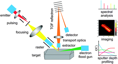
Basically, today different mass analysers with more or less high mass resolution exist. In this work, we focus on the most commonly used time of flight reflectron analyser. In Fig. 1, the functional principle of a modern reflectron ToF-SIMS machine is depicted. A pulsed bismuth primary ion beam is targeted to the sample surface. Depending on the investigated sample either Biz+ or Binz+-clusters are used as primary ions for analysis. In contrast to atomic Bi, the rate of fragmentation for organic molecules is significantly lower when using Bi-clusters. This is due to the comparatively low mean kinetic energy per cluster atom. During the collision process the primary ions penetrate slightly the surface and evoke a collision cascade resulting in the removal of neutrals, electrons and ions from few topmost atomic layers of the sample. With that, ToF-SIMS is one of the most surface sensitive techniques available today. An information depth of less than 1 nm is realized and is only exceeded by LEIS, low energy ion scattering, which probes only the first atomic layer of a sample.9 In contrast, X-ray photoelectron spectroscopy for example, as the most commonly used surface sensitive analysis tool in heterogeneous catalysis, has a probing depth of 1–10 nm.9
In ToF-SIMS, either cations or anions are collected using an applied electrical field and analysed in a time of flight analyser by their mass to charge ratio m/z. By the use of an ion reflector, the mass resolution m/Δm can be significantly increased up to >40![[thin space (1/6-em)]](https://www.rsc.org/images/entities/char_2009.gif) 000 FWHM (full width at half maximum). In comparison to other mass analysers, the reflectron ToF analyser combines several advantages like no theoretical upper mass limitation, high sensitivity, good mass resolution and detection of all masses within one analysis cycle. Due to the primary ion impact mainly electrons are emitted resulting in charging of non- and semi-conducting samples. Therefore the analysis of insulating samples was problematic until the development of pulsed low energy electron guns in the end of the 1980s.13 In the case of insulating samples, like many catalytic materials such as zeolites, the sample surface is flooded with low energetic electrons for charge compensation within the dead time during the time of flight analysis.
000 FWHM (full width at half maximum). In comparison to other mass analysers, the reflectron ToF analyser combines several advantages like no theoretical upper mass limitation, high sensitivity, good mass resolution and detection of all masses within one analysis cycle. Due to the primary ion impact mainly electrons are emitted resulting in charging of non- and semi-conducting samples. Therefore the analysis of insulating samples was problematic until the development of pulsed low energy electron guns in the end of the 1980s.13 In the case of insulating samples, like many catalytic materials such as zeolites, the sample surface is flooded with low energetic electrons for charge compensation within the dead time during the time of flight analysis.
By rastering the primary ion beam over the sample surface it is possible to obtain the mass distribution and composition of the sample surface – a so-called mass image. Usually within one mass image the intensity distribution of one selected mass is shown. The count rate for each pixel of the image is given by a brightness value. State of the art ToF-SIMS machines achieve maximum lateral resolutions of down to 60 nm for geometrically flat, conducting samples. This limitation is given by the primary ion beam diameter. There is a magic triangle linked to the performance of these liquid metal primary ion guns consisting of lateral resolution, signal intensity and mass resolution. Depending on the analytical task, a particular mode of operation is chosen. Unfortunately, no mode of operation exists, which shows the best performance for all three mentioned properties. The big advantage of modern ToF-SIMS machines is that they facilitate static as well as dynamic SIMS. For the latter a sputter gun, which produces much more intensive ion beams as the primary ion gun, is mounted on the machine. By alternating sputtering and analysing it is possible to remove the sample layer by layer and to obtain the 3D mass composition of the sample – ideally for flat samples. Typical analysis areas are 100 × 100 μm2 and up to 10 μm in depth. Since the beginning of 2013 focused ion beam (FIB) sources are also commercially available as an extension of SIMS machines, which allow producing a well prepared and bigger cross-section of a sample inside the ToF-SIMS chamber. After preparation, a mass image of the cross-section is taken. FIB ion guns are operated either with Ga+ or Bi+ ions. The latter have a 2–3 times better sputter efficiency. Using this technique it is easily possible to obtain mass images of cross-sections of up to 100 μm in depth within only a few hours. This enables the contamination free preparation and analysis of cross-sections, which will be a major advantage for the investigation of real, e.g. spent, catalyst materials.
One of the main disadvantages of ToF-SIMS is the high rate of fragmentation of the targeted molecules – a serious problem when it comes to the analysis of organic deposit species of e.g. coked zeolite samples. This leads mostly to complex mass spectra and the main task is to identify the parent molecules. Multivariate methods for spectra evaluation like principal component analysis (PCA) are used to overcome this problem.14 A good alternative might be the use of an argon cluster source as the primary ion gun. This technique was first used by Moritani et al.15 for SIMS analysis in 2008 and it was demonstrated by Rabbani et al.16 that the fragmentation rate of different polymer samples is drastically decreased by the use of argon-clusters in comparison to smaller primary ions, such as C60+. The projectiles consist of Arn+-clusters with n > 2000, which leads to very low mean kinetic energy per atom and as a consequence to a very soft sputter process with reduced fragmentation. A further aspect that must be kept in mind is the possible reduction of organic surface species by liberated secondary electrons. However at very low ion doses, this effect is mostly negligible.
Among all surface analysis techniques SIMS is the most sensitive one and thus has a high potential for the investigation of catalysts. The main drawback is that it is only a semi-quantitative method due to the dependence of the ionisation probability on the surrounding matrix. SIMS can be and has been used in different aspects of heterogeneous catalysis research – see reviews on this topic by Niemantsverdriet et al.5,9,17 and a recent review by Weng:18
• Surface and bulk characterisation of the catalyst
• Identification of decomposition products or intermediates at the surface
• Investigation of adsorbed gases/reactants on the catalyst surface
• Monitoring different stages of catalyst preparation
• Investigation of catalyst deactivation
Generally, for the first two aspects a commercially available SIMS machine can be used. The third aspect, surface science studies on mechanistic details of catalytic reactions, requires a dedicated SIMS machine which is equipped with options for sample cleaning, surface characterisation by LEED and XPS as well as options for sample heating, cooling and gas dosing. These requirements make such studies quite expensive, which might be the reason that actually only a few groups worldwide are working in this field. Nevertheless, the advantages over other methods are obvious:
• high surface sensitivity
• trace component detection
• hydrogen detection
• isotope sensitive; labelling possible
• molecular information on fragment ions/fragment ion pattern
In the following we will discuss three main directions of ToF-SIMS analysis of our selected showcase system of large ZSM-5 zeolite materials: (i) analysis of surface species with high mass resolution, (ii) 3D analysis of inorganic species by sputter depth profiling combined with ToF-SIMS analysis, and (iii) 2D imaging of secondary ions.
2 Large H-ZSM-5 zeolite crystals as model systems
As a showcase model of a catalytic system we present here large zeolite H-ZSM-5 crystals, which have been described in terms of their morphological, structural and catalytic properties quite extensively during the last years.19–24 Building on this background, large coffin-shaped zeolites have evolved as model catalysts for important Brønsted acid catalysed chemical processes, such as the methanol to hydrocarbons (MTH) reaction for production of alkenes or gasoline from methanol.25–27 Well-characterised facets are exposed at the surface with known pore orientation and morphological as well as acidic properties allowing to deduce structure–activity relationships. The reactivity of zeolite H-ZSM-5 is governed by accessible Brønsted acid sites in the bulk and on the surface of the crystals. However, during MTH reaction, these solid acid catalysts are prone to catalyst deactivation by formation of carbonaceous deposits (coke) blocking access to the active catalytic sites. Depending on the process conditions, the carbonaceous deposit species form either inside the zeolite pores or on the outer surface of the crystals.27,28 Surface species can be sensitively accessed by SIMS and thus, important insights can be obtained on chemical composition as well as lateral distribution, while species inside the porous system can be potentially analysed in combination with sputter depth profiling.SIMS is not only suitable to analyse carbonaceous species on the model crystals but also to follow the surface composition of samples during their different preparation stages: as-synthesized, template-containing, calcined, ion-exchanged, steamed, after post-synthesis modification, after reaction.
A validation of the ToF-SIMS results of large zeolite crystals can be obtained by studying powdered catalysts samples (small, industrially used H-ZSM-5 crystals with <1 μm size) in the form of pellets. In this case, the imaging mode of ToF-SIMS is not meaningful. However, high-resolution mass spectra can be obtained and compared with those of large H-ZSM-5 crystals.
Challenges in studying large H-ZSM-5 crystals are due to their electrical properties and size. As insulators, the measurements require a properly adjusted charge compensation to avoid charging effects especially at the geometrically exposed tips and edges of the crystals. Nevertheless, we show that both lateral and mass resolutions are sufficient enough to gain new insight into structure and catalytic properties of these model crystals. Table 2 summarizes all different ZSM-5 crystals analysed and discussed in this Perspective article. Further details on the ToF-SIMS experiments and sample preparation can be found in the ESI.†
| ZSM-5 sample | Abbreviation | Treatment |
|---|---|---|
| Templated | ZSM-5-T | As-prepared ZSM-5 directly after synthesis containing tetrapropyl ammonium (TPA) ions as the template |
| Ion-exchanged and calcined (parent) | H-ZSM-5-P | Calcined 30 min at 120 °C (2 °C min−1), 360 min at 550 °C (10 °C min−1), triple ion exchange with 10 wt% NH4NO3 at 80 °C, repeated 1st calcination to obtain H-form |
| Dealuminated by steaming | H-ZSM-5-MT | Mild steam treatment: 300 min at 500 °C in N2 (180 ml min−1) saturated with steam from boiling water |
| H-ZSM-5-ST | Severe steam treatment: 300 min at 700 °C in N2 (180 ml min−1) saturated with steam from boiling water | |
| After methanol-to-hydrocarbons reaction | H-ZSM-5-P-350 | 90 min MTH reaction at 350 °C in a Linkam microscopy cell with methanol (25 °C) saturated N2 (70 ml min−1) |
| H-ZSM-5-P-350-aged | As H-ZSM-5-P-350, followed by ageing for 14 h at 350 °C under pure N2 (70 ml min−1) | |
| H-ZSM-5-P-500 | 90 min MTH reaction at 500 °C in a Linkam microscopy cell with methanol (25 °C) saturated N2 (70 ml min−1) | |
| H-ZSM-5-MT-500 | As H-ZSM-5-P-500 | |
| H-ZSM-5-ST-500 | As H-ZSM-5-P-500 | |
3 High mass resolution surface analysis
Modern time of flight (ToF) as well as sector field and Fourier-Transform Ion Cyclotron Resonance (FT-ICR) mass analysers have a superior resolution of up to m/Δm = 3![[thin space (1/6-em)]](https://www.rsc.org/images/entities/char_2009.gif) 000
000![[thin space (1/6-em)]](https://www.rsc.org/images/entities/char_2009.gif) 000 (FT-ICR).10,11,29,30 These high-resolution instruments were not available in the early days when mainly quadrupole analysers were applied in static SIMS set-ups for heterogeneous catalysis research. We show here examples of how the high mass resolution of ToF-SIMS can be used to tackle questions on heterogeneous catalysis taking large H-ZSM-5 zeolite crystals as model systems.
000 (FT-ICR).10,11,29,30 These high-resolution instruments were not available in the early days when mainly quadrupole analysers were applied in static SIMS set-ups for heterogeneous catalysis research. We show here examples of how the high mass resolution of ToF-SIMS can be used to tackle questions on heterogeneous catalysis taking large H-ZSM-5 zeolite crystals as model systems.
With the mass resolution of a modern ToF-SIMS instrument, detailed analysis and discussion of fragment ion pattern resulting from catalyst samples becomes possible. A more complete treatment of surface adsorbate composition and chemical structure can be achieved. Multivariate data analysis protocols like principal component analysis can aid assignment and origin of fragment groups. The introduction of ToF-SIMS enabled studies of solid oxide surfaces and chemical speciation of the desorbing fragments.31 Groenewold et al. have studied zeolite materials by ToF-SIMS, quadrupole SIMS and ion trap SIMS and compared the three mass analysing methods with respect to their ability to detect oligomeric oxyanions AlmSinO2(m+n)H(m−1).32 Analysing these larger fragments, the authors strived for deeper insight into zeolite surface composition, since older SIMS methods mainly yielded atomic and small cluster fragment ions,33–35 limited both by mass resolution and the stability of larger fragment ions in the analysers. Ion gas phase stability has to be considered carefully as it impacts on the abundance of larger fragments.36
As mentioned above, SIMS is a semi-quantitative method because of matrix effects. Also during analysis of H-ZSM-5 zeolite crystals matrix effects have to be taken into account, since the ion yield of each fragment depends on the substrate composition where the ion desorbs from.37 Thus, we used relative enhancements (RE) of a fragment ion X+ (eqn (1)) when the presence of certain fragment ions on a spent catalyst sample is to be discussed, taking a fresh catalyst sample, ideally of the same material batch, as reference.
 | (1) |
Pure zeolites: from synthesis to post-synthesis treatments
Large zeolite H-ZSM-5 crystals, possessing the MFI framework structure, are commonly prepared by a hydrothermal synthesis route making use of structure directing agents (SDAs), such as tetraalkylammonium salts.19 In the case of the H-ZSM-5 crystals under investigation, tetrapropylammonium hydroxide has been used as the SDA. ToF-SIMS analysis of the as-synthesised crystals, ZSM-5-T, shows the presence of both template related and inorganic secondary ions. The high mass resolution of the ToF analyser (see also Fig. S1, ESI† for another example) allows for the safe assignment of higher mass fragments, such as C12H28N+ (m/z = 186.21), which is the tetrapropylammonium parent cation. Also (stable) fragment ions derived from the template can be observed and related to split-off of propyl groups (C9H20N+, m/z = 142.15; C6H12N+, m/z = 98.09; C3H6N+, m/z = 56.05) with the nitrogen atom keeping its 4-fold coordination. During primary ion sputtering their intensity drops showing, that their presence is more pronounced in the very first surface layers of the crystals.To yield a catalytically active material, the as-synthesised material needs to be calcined to burn the template and to be transferred into its proton-exchanged form, i.e. parent H-ZSM-5-P. The surface of active zeolite H-ZSM-5-P releases mostly inorganic fragment species. Most abundant fragments are: Si+, m/z = 27.98; SiH+, m/z = 28.99; AlO+, m/z = 42.98; SiOH+, m/z = 44.98, AlH+, m/z = 27.99. Besides zeolite-based fragments, organic deposits can be found on the crystals’ surface originating from contaminations due to sample transport and fixation.
Post-synthetic treatments of zeolite materials are commonly used to optimize catalyst deactivation behaviour (e.g., coke formation) during reaction. Among these after-treatments one successful method is dealumination of the zeolite by a steam treatment, so-called steaming.38 Steaming of large zeolite H-ZSM-5 crystals has been recently investigated by Aramburo et al.22,24 Dealumination by steaming under mild conditions (i.e., at 500 °C, H-ZSM-5-MT) leads to the introduction of surface mesoporosity, while steaming under severe conditions (i.e., at 700 °C, H-ZSM-5-ST) gives pronounced mesoporosity also in the bulk of the crystal.
Furthermore, the density of Brønsted acid sites is reduced especially in the surface near regions of the crystals, which leads to less pronounced carbonaceous deposit formation during MTH reaction. Deactivation of these dealuminated crystals proceeds with a slower rate than that of parent H-ZSM-5 crystals, which is beneficial for the overall reaction engineering.
Particularly interesting is the nature of the surface exposed providing directly accessible Brønsted acid sites. ToF-SIMS could potentially yield insight into the distribution and the nature of these sites by mapping site-specific fragment ions. However, this has not been experimentally proven yet.
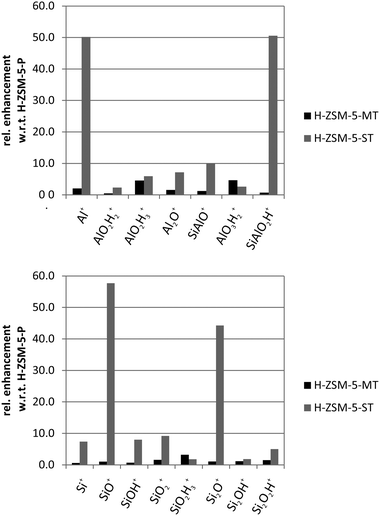
Another important and open question is the way dealumination proceeds and where removed framework Al species remain after steaming. ToF-SIMS analysis of parent H-ZSM-5, H-ZSM-5-MT and H-ZSM-5-ST revealed that on the outer surface of severely steamed H-ZSM-5-ST (700 °C) crystals, Al+ and SiAlO2H+ (>50×) can be detected in large amounts as compared to parent and mildly steamed crystals as shown in Fig. 2.
Carbonaceous deposits on deactivated zeolite catalyst samples: H-ZSM-5 in the MTH reaction
An important requirement for a solid catalyst during real life operation is its overall stability. Catalyst instabilities and deactivation lead to expensive, uneconomic shutdowns of chemical reactors for catalyst exchange or intermediate treatments for regeneration. The methanol-to-hydrocarbons (MTH) process employs molecular sieves, such as the microporous silicoaluminophosphate H-SAPO-34 and microporous aluminosilicate H-ZSM-5, as catalyst materials. The catalytic centres are considered to be Brønsted acid sites located within the pores and channels as well as on the surface of these molecular sieves.Coke formation during the MTH reaction on H-ZSM-5 is believed to result from further condensation of the active scaffolds running the catalytic cycle: polymethylated benzenium ions. Catalyst deactivation is thus directly connected to catalytic turnover and product formation. Depending on the reaction temperature and acidity (strength and number of acid sites), different carbonaceous deposits form in different places hampering catalytic activity. With the complementary application of ToF-SIMS and dissolution of the zeolite matrix in hydrofluoric acid followed by extraction of the aqueous phase with dichloromethane and subsequent analysis by GC-MS, both surface-prone, insoluble and soluble, internal carbonaceous deposits, respectively, have been analysed in a recent study of our group.27
Depending on the reaction temperature of the MTH reaction the ratio and chemical nature of surface and internal carbonaceous deposits changed. In Fig. 3, CxHy+ fragments resulting from used H-ZSM-5 samples reacted at different temperatures are shown. The fragments are grouped based on the H/C ratio and their cumulated relative enhancement per H/C ratio fragment group is displayed, the ratio being compared to a fresh reference crystal, i.e. relative enhancement (eqn (1)).
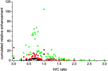 | ||
| Fig. 3 Evaluation of cumulated relative enhancements (ToF-SIMS) of carbonaceous species on large H-ZSM-5 crystals classified according to their H/C ratio as a function of MTH reaction temperature (350 and 500 °C; black squares and green triangles, respectively) and inert-gas ageing treatment (N2 flow, 350 °C, red circles). Reproduced from ref. 27 with permission of Wiley-VCH. | ||
While Fig. 3 gives an overview of the enhancement pattern of all analysed fragments, Fig. 4 (top) shows specific CxHy+ fragments relating to so-called hydrocarbon pool species such as benzene and methylated benzenes on the surface of the tested crystals suitable for a detailed discussion. Note that at higher MTH reaction temperature (500 °C), all fragments are most enhanced. Larger fragments (Fig. 4, bottom) most likely result from carbonaceous deposits from the zeolite surface that have condensed towards larger polyaromatics such as naphthalenes, anthracenes, pyrenes. Further ageing of the coked crystals at 350 °C under inert gas leads to a pronounced formation of graphite-like carbon species, i.e. C2+.
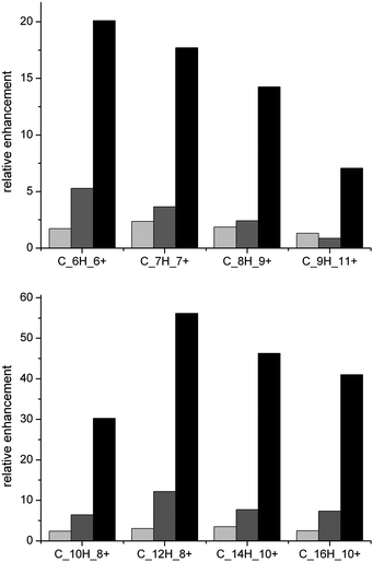 | ||
| Fig. 4 Relative enhancement of CxHy+ fragments from ToF-SIMS measurements that belong to (top) methylated benzenes and (bottom) methylated polyaromatic species after MTH reaction at different temperatures (350, 500 °C; light grey and black bars, respectively) on parent large H-ZSM-5 crystals and after aging of coked large H-ZSM-5 crystals (MTH at 350 °C, aging for 14 h at 350 °C in N2 flow; dark grey bars). Reproduced from ref. 27 with permission of Wiley-VCH. | ||
Further analysis of the fragment ion pattern – here specifically carbonaceous deposit related CxHy+ fragments – in correlation with experimental conditions could potentially be achieved by the use of principal component and multivariate data analysis methods.39,40
4 Depth profiling
Sputter depth profiling of large ZSM-5 crystals can yield valuable information on the 3D distribution of inorganic as well as organic species. For example, the Si/Al ratio can vary throughout the crystal with gradients perpendicular to the surface41 having implications on both crystal growth and the distribution of catalytic activity. Henry et al. have reported recently on sputter depth profiling analysis of the Si/Al ratio on various powder H-ZSM-5 catalyst samples,42 yielding an average value for the Si/Al ratio with progressing Ar+ sputtering time, i.e. depth.35 These results are particularly interesting when analysing heterogeneities in Al distribution over the zeolite crystals (so-called Al-zoning),43–45 as the distribution of Al relates to the distribution of Brønsted acid sites. A recent study of our group focused on synchrotron-based micrometre resolved X-ray diffraction imaging (μXRD) to study the intergrowth and Al zoning of large H-ZSM-5 crystals.46Fig. 5 shows a synopsis of both μXRD based Al zoning, taking subtle lattice parameter increases induced by Al substitution into account, and the corresponding ToF-SIMS based sputter depth profiling analysis of Si+ and Al+ as secondary. The studied large H-ZSM-5 crystals reveal a Si rich crystal centre and a rim-like Al enrichment closer to the crystal surface. Regarding organic species, probing the 3D distribution of carbonaceous deposit species with sputter depth profiling after coking of the H-ZSM-5 zeolites in the MTH reaction, would yield valuable insight into the different chemical nature and location of surface (hard) and bulk (soft) coke.27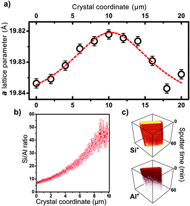 | ||
| Fig. 5 Evidence for the presence of an aluminium gradient along the short crystal axis (size 100 × 20 × 20 μm3). (a) The a lattice parameter plotted along the short crystal axis as derived from μXRD of the (18 0 0) reflection of the ZSM-5 (MFI) framework. (b) ToF-SIMS sputter depth profiling of the crystal indicating the estimated Si/Al ratio. (c) 3-D representation of depth profiles of Si+ and Al+ secondary ions, as a function of sputter time. Reproduced from ref. 46 with permission of Wiley-VCH. | ||
In depth profiling analyses sputter rate calibration is a particularly difficult task. The small size, geometry and insulator properties of zeolite particles lead to inhomogeneous sputtering profiles during repeated sputter-measurement cycles. Furthermore, during prolonged sputtering, both sputtering and primary ion guns become slightly defocused while the sample changes its morphology/height profile. To account for the issue of sputter rate calibration, recently combined scanning probe microscopy-ToF-SIMS instruments have been developed, where the topography of the sample during sputter depth profiling can be assessed in situ.47–50 Optical microscopy methods such as confocal microscopy and digital holographic microscopy after sputtering height profiling are further techniques to evaluate sputter rates by quantifying the geometry of the sputtered objects or sputter craters.50 Nevertheless none of these instruments has been used to study catalytically relevant samples yet.
5 Imaging of surface species on a single catalyst particle level
The advancement of ion gun design has led to an increased lateral resolution. Primary ion beam diameters down to 60 nm are possible to realise, however at the expense of secondary ion yields and mass resolution. Individual inorganic nano-objects in the form of AlOOH whiskers have been studied recently by Pinnick et al. employing ToF-SIMS, however not in imaging mode.51 FT-ICR-SIMS has the potential to combine both highest lateral resolution with ultimate mass resolution and sensitivity, making it the most powerful imaging SIMS technique. However, the availability of FT-ICR-SIMS is still very limited10,11 and lateral resolution has not been pushed to the limits yet. Another challenge for imaging SIMS on insulating materials is to optimize charge compensation by an electron flood gun to achieve best possible mass as well as lateral resolution. Zeolites are inherently insulators and the habitus of large zeolites crystals includes edges and tips where electric field distortions are likely to occur with negative influence on both lateral and mass resolution. The lateral resolution on zeolites is in the same order of magnitude of the optical resolution of standard optical microscopes. The limited lateral resolution on 3D, insulating objects makes the large zeolite crystals ideal candidates for ToF-SIMS imaging studies as their shape and expected spatial heterogeneities are in the μm range.Meaningful imaging however is connected with some inherent difficulties arising from surface contamination due to sample preparation, transport and fixation. Zeolite samples are commonly prepared, reacted and retrieved from a reactor under atmospheric conditions, samples are transported in ambient air. Consequently, the very first layers on the surface of the samples are not the actual zeolite surface, but contaminant species. Also the pressure in the UHV measurement chamber might not be ideal (i.e. 10−8 mbar results in the adsorption of ∼1 monolayer of background gas onto the surface in 100 s, assuming a sticking coefficient of 1).
In view of the very low ion dose per analysed area only the very first layers are probed in imaging mode, i.e. under standard circumstances and sample preparation this is most likely dirt/adsorption from background pressure or external atmosphere. Fig. 6 nicely illustrates the adsorption of background gas species onto a freshly sputtered area on a large zeolite crystal. On the left side, an area of 10 × 10 μm2 (black area in the left image) has been sputtered with Bi3++ primary ions at a high dose to record a high-resolution secondary ion mass spectrum. Immediately after the spectrum has been taken, the sample was analysed by ToF-SIMS imaging, each consecutive scan took 92 s. Only after two scans, the depleted area was filled with the contaminant species (m/z = 73) again.
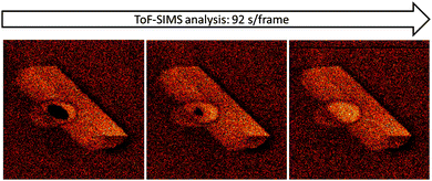 | ||
| Fig. 6 ToF-SIMS imaging of large H-ZSM-5 crystals with a time sequence (Δt = 92 s) on m/z = 73, showing the re-adsorption of species from background pressure of the UHV chamber. | ||
The effect of a very low ion dose during the ToF-SIMS imaging becomes even clearer from the primary ion sputter time dependency of selected fragments, as shown in Fig. 7.
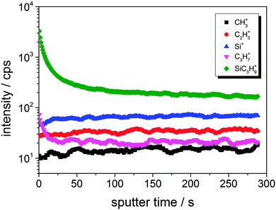 | ||
| Fig. 7 Bi3++ sputtering time dependent intensity of secondary ion intensities resulting from a large H-ZSM-5 crystal. | ||
In high-current bunched mode (i.e. high primary ion dose for high resolution mass analysis), signals attributed to SiC3H9+ and C3H7+, which are dominating the very first surface layers, decrease rapidly within the first 50 s of measurement time, while zeolite-related fragments, such as Si+, increase in intensity during that period. The applied Bi3++ primary ion currents were in the range of 0.5 pA for high mass resolution spectra (high current bunched mode, approximately 10 × 10 μm2, 260 s). Under these conditions, statistically about 0.5 Bi3++ primary ions impinged per surface atom in the whole measuring period (assuming 1015 surface atoms per cm2). In imaging mode, the incident current was lower (0.12 pA) and the area was larger 120 × 120 μm2, resulting in ∼2 × 10⁻⁴ hits per surface atom in the period of 1 frame (92 s). The effect of contaminants on the detected species in imaging mode is thus by a factor of 2000 higher than in the spectral high current bunch mode. Therefore, meaningful imaging requires a very well prepared, clean sample. Careful sputter cleaning of the surface to be studied in advance might be necessary as well.
Local heterogeneities in inorganic species could though be studied by ToF-SIMS in the imaging mode. Fig. 8 exemplifies the heterogeneous distribution of Na+ ions over a detemplated, calcined and subsequently ion-exchanged zeolite H-ZSM-5 after reaction under MTH conditions. The lateral heterogeneities on the surface of the crystal relate most probably to surface defects in the zeolite crystals. The as-synthesised material contains Na+ ions as counter ions added to the initial synthesis mixture either as NaOH or NaHCO3. To get the proton (H+) form of the material, Na+ is ion-exchanged in dilute aqueous NH3 solution yielding the ammonium form, which is then transformed into the H-form by another calcination step. The Na+ distribution in Fig. 8 reveals that the exchange of Na+ by NH4+ might be incomplete and results in regions, which are rich in Na+ ions. The presence of Na+, however, indicates the absence of H+ and thus the absence of Brønsted acid sites, which in turn has a direct influence on the catalytic activity of the zeolite crystal. As such, these heterogeneities are assessed by ToF-SIMS on a single particle level showing nicely how different single large H-ZSM-5 particles should behave in terms of local surface reactivity.
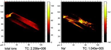 | ||
| Fig. 8 Na+ ion heterogeneities on a severely steamed large zeolite H-ZSM-5-ST-500 crystal after performing the MTH reaction at 500 °C. Left: total ion image, right: Na+ ion image. | ||
6 Conclusions and outlook
Despite the valuable insights SIMS techniques have provided in the 1990’s on both model (i.e., single crystals) and powdered catalyst materials, there has been no widespread use in the field of heterogeneous catalysis as compared to e.g. XPS. Reasons for that might be the more complicated set-up and significantly higher investment costs for ToF-SIMS instruments accompanied by the complex nature of the obtained mass spectra.As a surface science technique ToF-SIMS requires a UHV environment. For zeolite catalysis, this implies, that sample analysis can only be carried out ex situ, i.e. after treatment or reaction of the catalyst sample. Compared to other surface sensitive UHV based methods, ToF-SIMS yields insights into adsorbate composition by fragment ion patterns resulting from the very first surface layers of the sample. The fragment ion pattern complements data obtained from electron spectroscopies (XPS and Auger electron spectroscopy) on oxidation states of the atomic species. Compared to bulk optical, vibrational and X-ray absorption spectroscopy or X-ray diffraction catalyst characterization techniques commonly used in situ, ToF-SIMS complements these with surface specific chemical information on fragment ion composition and also gives further hints on possible structural features of the adsorbates. Ultimately, the presented advantages of ToF-SIMS – surface sensitivity, chemical specificity in terms of fragment ion sum formulas, detection sensitivity, and 2D/3D imaging capabilities – are most useful for zeolite catalyst analysis when used in combination with other techniques.
The recent developments of SIMS techniques are promising and more breakthroughs are clearly to be expected. In principle, using FT-ICR-SIMS it should be possible to operate at ultra-high resolution in both mass and space with the sensitivity for a few fragment ions. With that, the detection and analysis of single catalytically active sites on not only large zeolite crystals should be possible even in imaging mode. One can envisage the spatiotemporal analysis of pore mouths on the outer surface of large zeolite crystals being the entrance doors to the crystal bulk. The nature of the pore mouths is still intriguing as it determines both reactivity and diffusion properties of molecular sieves. The ultimate lateral and spatial resolution combined with a finely adjusted charge compensation may allow for the mass spectrometric analysis and imaging of small, industrially relevant zeolite particles.52 Furthermore, the application of SIMS is not limited to zeolitic systems, but also has large potential to provide a closer look at e.g. supported metal or metal oxide catalysts as well as electrocatalysts as summarized in a very recent review by Weng.18 With that outlook we would like to stimulate researchers to enter the field and make use of advanced SIMS techniques to study catalytic solids, since we believe that there are much more interesting details of catalytic solids to be discovered.
Acknowledgements
J.P.H. acknowledges financing from the German Research Foundation (DFG, postdoctoral fellowship Ho4579/1-1) for a postdoctoral fellowship at Utrecht University, while B.M.W. acknowledges the Dutch National Research School Combination Catalysis (NRSC-C) and NWO-CW (Top research grant) for financial support. The authors thank Prof. Dr Jürgen Janek for providing access to the ToF-SIMS facilities at JLU Giessen. Dr Luis Aramburo, Hendrik van der Bij, Qinyun Qian, Dr Javier Ruiz-Martínez, and Zoran Ristanović (all from Utrecht University) are thanked for fruitful discussions about zeolite catalysis, while Dr Machteld Mertens (ExxonMobil, Machelen, Belgium) is acknowledged for providing the large zeolite H-ZSM-5 crystals. Dr L. Aramburo, H. van der Bij, and Z. Ristanovic are thanked for providing differently treated ZSM-5 crystals presented in this Perspective.Notes and references
- J. Thomson, Philos. Mag., 1910, 20, 752–767 CrossRef.
- K. S. Woodstock, Phys. Rev., 1931, 38, 1696–1703 CrossRef.
- R. F. K. Herzog and F. P. Viehböck, Phys. Rev., 1949, 76, 855–856 CrossRef CAS.
- A. Benninghoven, Z. Phys., 1970, 230, 403–417 CrossRef CAS.
- J. C. Vickerman and D. Briggs, ToF-SIMS: Surface Analysis by Mass Spectrometry, IM Publications LLP, Chichester, 2001 Search PubMed.
- R. E. Honig, Int. J. Mass Spectrom. Ion Processes, 1985, 66, 31–54 CrossRef CAS.
- M. S. Burns, J. Microsc., 1982, 127, 237–258 CrossRef CAS.
- K. Wittmaack, Vacuum, 1982, 32, 65–89 CrossRef CAS.
- J. Niemantsverdriet, Spectroscopy in Catalysis: An Introduction, Wiley-VCH, Weinheim, 3rd edn, 2007 Search PubMed.
- D. F. Smith, E. W. Robinson, A. V. Tolmachev, R. M. A. Heeren and L. Pasa-Tolic, Anal. Chem., 2011, 83, 9552–9556 CrossRef CAS PubMed.
- D. F. Smith, A. Kiss, I. Leach, E. Franklin, E. W. Robinson, L. Pasa-Tolic and R. M. A. Heeren, Anal. Bioanal. Chem., 2013, 1–8 Search PubMed.
- J. C. Vickerman and D. Briggs, ToF-SIMS: Materials Analysis by Mass Spectrometry, IM Publications LLP, and SurfaceSpectra Ltd., Chichester and Manchester, 2013 Search PubMed.
- B. Hagenhoff, D. van Leyen, E. Niehuis and A. Benninghoven, J. Vac. Sci. Technol., A, 1989, 7, 3056–3064 CAS.
- D. J. Graham and D. G. Castner, Biointerphases, 2012, 7, 1–12 CrossRef PubMed.
- K. Moritani, M. Hashinokuchi, J. Nakagawa, T. Kashiwagi, N. Toyoda and K. Mochiji, Appl. Surf. Sci., 2008, 255, 948–950 CrossRef CAS PubMed.
- S. Rabbani, A. M. Barber, J. S. Fletcher, N. P. Lockyer and J. C. Vickerman, Anal. Chem., 2011, 83, 3793–3800 CrossRef CAS PubMed.
- J. J. Spivey, S. K. Agarwal, H. J. Borg and J. Niemantsverdriet, Catalysis: Applications of Secondary Ion Mass Spectrometry in Catalysis and Surface Chemistry, Royal Society of Chemistry, Cambridge, 1994, vol. 11, pp. 1–50 Search PubMed.
- L.-T. Weng, Appl. Catal., A, 2013 DOI:10.1016/j.apcata.2013.08.029.
- J. Kornatowski, Zeolites, 1988, 8, 77–78 CrossRef CAS.
- E. Stavitski, M. R. Drury, D. A. M. de Winter, M. H. F. Kox and B. M. Weckhuysen, Angew. Chem., Int. Ed., 2008, 47, 5637–5640 CrossRef CAS PubMed.
- L. Karwacki, M. H. F. Kox, D. A. Matthijs de Winter, M. R. Drury, J. D. Meeldijk, E. Stavitski, W. Schmidt, M. Mertens, P. Cubillas, N. John, A. Chan, N. Kahn, S. R. Bare, M. Anderson, J. Kornatowski and B. M. Weckhuysen, Nat. Mater., 2009, 8, 959–965 CrossRef CAS PubMed.
- L. R. Aramburo, L. Karwacki, P. Cubillas, S. Asahina, D. A. M. de Winter, M. R. Drury, I. L. C. Buurmans, E. Stavitski, D. Mores, M. Daturi, P. Bazin, P. Dumas, F. Thibault-Starzyk, J. A. Post, M. W. Anderson, O. Terasaki and B. M. Weckhuysen, Chem.–Eur. J., 2011, 17, 13773–13781 CrossRef CAS PubMed.
- M. B. J. Roeffaers, R. Ameloot, M. Baruah, H. Uji-i, M. Bulut, G. De Cremer, U. Müller, P. A. Jacobs, J. Hofkens, B. F. Sels and D. E. De Vos, J. Am. Chem. Soc., 2008, 130, 5763–5772 CrossRef CAS PubMed.
- L. R. Aramburo, J. Ruiz-Martinez, J. P. Hofmann and B. M. Weckhuysen, Catal. Sci. Technol., 2013, 3, 1208–1214 CAS.
- D. Mores, E. Stavitski, M. Kox, J. Kornatowski, U. Olsbye and B. Weckhuysen, Chem.–Eur. J., 2008, 14, 11320–11327 CrossRef CAS PubMed.
- D. Mores, J. Kornatowski, U. Olsbye and B. M. Weckhuysen, Chem.–Eur. J., 2011, 17, 2874–2884 CrossRef CAS PubMed.
- J. P. Hofmann, D. Mores, L. R. Aramburo, S. Teketel, M. Rohnke, J. Janek, U. Olsbye and B. M. Weckhuysen, Chem.–Eur. J., 2013, 19, 8533–8542 CrossRef CAS PubMed.
- H. Schulz, Catal. Today, 2010, 154, 183–194 CrossRef CAS PubMed.
- G. E. Johnson, M. Lysonski and J. Laskin, Anal. Chem., 2010, 82, 5718–5727 CrossRef CAS PubMed.
- J. A. Whitby, F. Ostlund, P. Horvath, M. Gabureac, J. L. Riesterer, I. Utke, M. Hohl, L. Sedlacek, J. Jiruse, V. Friedli, M. Bechelany and J. Michler, Adv. Mater. Sci. Eng., 2012, 2012, 180437 Search PubMed.
- E. Cuynen, L. Van Vaeck and P. Van Espen, Rapid Commun. Mass Spectrom., 1999, 13, 2287–2301 CrossRef CAS.
- G. S. Groenewold, G. F. Kessinger, J. R. Scott, A. K. Gianotto, A. D. Appelhans, J. E. Delmore and R. Avci, Anal. Chem., 2001, 73, 226–232 CrossRef CAS.
- S. J. Reed, Mineral. Mag., 1989, 53, 3–24 CAS.
- N. MacRae, P. Bottazzi, L. Ottolini and R. Vannucci, Chem. Geol., 1993, 103, 45–54 CrossRef CAS.
- Q. Wang, M. Torrealba, G. Giannetto, M. Guisnet, G. Perot, M. Cahoreau and J. Caisso, Zeolites, 1990, 10, 703–706 CrossRef CAS.
- S. Verdier, J. B. Metson and H. M. Dunlop, J. Mass Spectrom., 2007, 42, 11–19 CrossRef CAS PubMed.
- V. R. Deline, W. Katz, J. C. A. Evans and P. Williams, Appl. Phys. Lett., 1978, 33, 832–835 CrossRef CAS PubMed.
- Y. Tao, H. Kanoh, L. Abrams and K. Kaneko, Chem. Rev., 2006, 106, 896–910 CrossRef CAS PubMed.
- M. L. Pacholski, Appl. Surf. Sci., 2004, 231–232, 235–239 CrossRef CAS PubMed.
- M. Wagner, D. Graham and D. Castner, Appl. Surf. Sci., 2006, 252, 6575–6581 CrossRef CAS PubMed.
- N. Danilina, F. Krumeich, S. A. Castelanelli and J. A. van Bokhoven, J. Phys. Chem. C, 2010, 114, 6640–6645 CAS.
- M. Henry, M. Bulut, W. Vermandel, B. Sels, P. Jacobs, D. Minoux, N. Nesterenko and J. Dath, Appl. Catal., A, 2012, 437–438, 96–103 CrossRef CAS PubMed.
- J. Dwyer, F. R. Fitch, F. Machado, G. Qin, S. M. Smyth and J. C. Vickerman, J. Chem. Soc., Chem. Commun., 1981, 422–424 RSC.
- J. Dwyer, F. R. Fitch, G. Qin and J. C. Vickerman, J. Phys. Chem., 1982, 86, 4574–4578 CrossRef CAS.
- B. Meyers, T. Fleisch and C. Marshall, Appl. Surf. Sci., 1986, 26, 503–516 CrossRef CAS.
- Z. Ristanovic, J. P. Hofmann, U. Deka, T. U. Schülli, M. Rohnke, A. M. Beale and B. M. Weckhuysen, Angew. Chem., Int. Ed., 2013, 52, 13382–13386 CrossRef CAS PubMed.
- S. L. S. Stipp, A. J. Kulik, K. Franzreb, W. Benoit and H. J. Mathieu, Surf. Interface Anal., 1997, 25, 959–965 CrossRef CAS.
- M. L. Wagter, A. H. Clarke, K. F. Taylor, P. A. W. van der Heide and N. S. McIntyre, Surf. Interface Anal., 1997, 25, 788–789 CrossRef CAS.
- T. Wirtz, Y. Fleming, U. Gysin, T. Glatzel, U. Wegmann, E. Meyer, U. Maier and J. Rychen, Surf. Interface Anal., 2013, 45, 513–516 CrossRef CAS.
- S. Koch, G. Ziegler and H. Hutter, Anal. Bioanal. Chem., 2013, 1–7 CAS.
- V. Pinnick, S. Rajagopalachary, S. V. Verkhoturov, L. Kaledin and E. A. Schweikert, Anal. Chem., 2008, 80, 9052–9057 CrossRef CAS PubMed.
- W. Lamberti, W. Horn and J. Keenan, Microsc. Microanal., 2007, 13(suppl2), 564–565 Search PubMed.
Footnote |
| † Electronic supplementary information (ESI) available. See DOI: 10.1039/c3cp54337d |
| This journal is © the Owner Societies 2014 |


