 Open Access Article
Creative Commons Attribution 3.0 Unported Licence
A combined stretching–tilting mechanism produces negative, zero and positive linear thermal expansion in a semi-flexible Cd(II)-MOF†
Prem
Lama
,
Raj Kumar
Das
,
Vincent J.
Smith
and
Leonard J.
Barbour
*
Department of Chemistry and Polymer Science, University of Stellenbosch, Matieland, 7602, Stellenbosch, South Africa. E-mail: ljb@sun.ac.za
First published on 1st May 2014
Abstract
A novel semi-flexible Cd(II)-MOF has been synthesized and characterized by variable temperature powder and single-crystal X-ray diffraction. The material displays an unusual combination of thermal expansion (TE) i.e. negative, zero and positive, which is an extremely rare finding, especially for metal–organic frameworks as a result of a combined stretching–tilting mechanism.
Most solid materials expand along all directions upon heating – a phenomenon known as positive thermal expansion (PTE).1 The coefficients (αi) of positive linear thermal expansion are usually in the order of about 20 MK−1.2 However, in a few known instances specific mechanical phenomena or packing arrangements in the solid state lead to anomalous thermal expansion behavior such that extraordinarily large PTE (>100 MK−1) or negative thermal expansion (NTE) occurs.3 Materials that possess geometric flexibility can undergo expansion along one particular direction, leading to contraction along the perpendicular directions (or vice versa) as a consequence of scissor- or hinge-like thermal responses.4 Several organic and metal–organic materials such as Ag3[Co(CN)6] and the Prussian blue analogues have been reported to possess large anisotropic thermal expansion coefficients.5 MOFs have recently attracted significant interest owing to their novel architectures as well as their potential applications as functional materials.6 Moreover, materials such as cyanide-bridged MOFs,7 HKUST-1 (Cu(II)-1,3,5-BTC)8 and IRMOFs9 display isotropic negative thermal expansion. A few magnetic materials exist in which increased thermal motion is negated by effects due to a change in the magnetic ordering, thus resulting in overall zero thermal expansion (ZTE) within a particular temperature range.10 We also note that some MOF are known to undergo combined PTE, NTE and ZTE based on either hinge or lattice fence mechanisms.4b,c
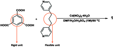
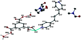
Here we report the design and synthesis of a semi-flexible MOF {[Cd(HBTC)(BPP)]·1.5DMF·2H2O}n (1) containing mono-protonated 1,3,5-benzetricarboxylate (HBTC2−) as the rigid part and 1,3-bis(4-pyridyl)propane (BPP) as the flexible unit (Scheme 1). 1 crystallizes in the triclinic space group P![[1 with combining macron]](https://www.rsc.org/images/entities/char_0031_0304.gif) . The asymmetric unit contains one Cd2+ ion, one HBTC2− ligand, one BPP ligand, two water molecules and 1.5 disordered DMF molecules (Fig. 1).
. The asymmetric unit contains one Cd2+ ion, one HBTC2− ligand, one BPP ligand, two water molecules and 1.5 disordered DMF molecules (Fig. 1).
Of the three carboxyl groups of BTC only two are deprotonated and they bind to the metal ion in chelate-bridging and chelating modes (Fig. S1, ESI†) to form a dinuclear Cd2 secondary building unit. The BPP ligands coordinate to the Cd centers to form a Cd2(BPP)2 macrocyclic unit, which is approximately co-planar to the crystallographic bc plane (Fig. S2, ESI†), whereas the aromatic ring of HBTC2− is oriented parallel to the crystallographic ab plane. Thus the interconnected Cd2BPP2 macrocyclic units form a 2D layer parallel to (011). Each layer contains solvent-accessible channels along [100] with dimensions ∼3.1 × 9.7 Å (taking into account the contributions of the van der Waals radii of the atoms). The channels are occupied by some of the disordered DMF and water molecules while the carboxylic acid group remains uncoordinated, forming O–H⋯O and C–H⋯O hydrogen bonding interactions (Fig. S3, ESI†) with the remaining water molecules and the BPP ligands. The overall 3D architecture of the framework has an ⋯ABAB⋯ stacking arrangement (Fig. 2) and the remaining DMF molecules occupy the interstitial positions between the layers.
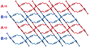 | ||
| Fig. 2 Packing diagram viewed along [100] showing ⋯ABAB⋯ stacking of 2D layers in 1 (guest molecules and hydrogen atoms have been omitted for clarity). | ||
In order to monitor temperature dependent structural changes, a variable-temperature single-crystal X-ray diffraction (VT-SCD) study was carried out. Starting at 100 K, intensity data were recorded at 20 K intervals; data collection above 260 K was not feasible owing to solvent loss and degradation of the single crystal. The variation of crystallographic axes and angles with temperature are shown in Fig. S4 and S5 (ESI†). Since 1 crystallizes in the triclinic crystal system, the coefficients of thermal expansion were calculated using the program PASCal.11b
The expansion coefficients along the three principal axes X1 along fractional coordinate vectors (0.4920, 0.7734, −0.3997), X2 (0.9134, −0.4041, −0.0480) and X3 (0.0575, 0.1605, 0.9854) are −43.4(7), 2(1) and 133(2) MK−1, respectively (Fig. 3 and 4). The volumetric thermal expansion coefficient αv = 91(2) MK−1 (Fig. S6, ESI†).
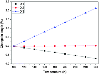 | ||
| Fig. 3 Variation of principal tensor lengths (obtained from PASCal)11b with temperature in 1. | ||
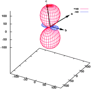 | ||
| Fig. 4 PASCal11b expansivity tensor plot for 1. | ||
Expansion data obtained from PASCal were verified against data obtained from the program Win_strain11 (see ESI†) and found to be in close agreement. Thus 1 displays NTE along X1, ZTE along X2 and PTE along X3 (Fig. 5).
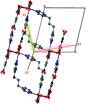 | ||
| Fig. 5 The orthogonal directions of the principal axes, X1 (NTE) and X3 (PTE) projected onto the crystallographic bc plane of 1. | ||
The reversibility of the thermal expansion phenomenon was verified by determining the unit cell dimensions after rapid cooling to 100 K, heating back to 260 K and then cooling again to 100 K (100-R in the ESI†). The initial and final unit cell dimensions at 100 K were approximately equal, and the temperature cycling did not appear to cause significant degradation of the crystal mosaicity.
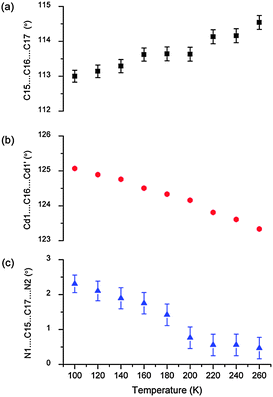
Using the VT-SCD data, temperature-dependent changes in the conformation of the framework were examined in order to elucidate the mechanism of this rare thermal expansion behavior. Upon heating, the Cd2BPP2 macrocyclic unit undergoes expansion diagonally (d) across the macrocycle (αd = 104(1) MK−1), as is evident from the elongation of the non-bonding distances C15⋯C16′, C12⋯C17′ and N1⋯i1 (Table 1, Fig. 6, Fig. S7–S14, ESI†). The aliphatic unit of the BPP ligand (approximately parallel to X1) bends, as evidenced by an increase in the bond angle C15⋯C16⋯C17 and a decrease in the Cd1⋯C16⋯Cd1′ non-bonding angles with increasing temperature. A decrease in the torsion angle N1⋯C15⋯C17⋯N2 also occurs during this process (Table 2, Fig. 7). Concomitantly, the macrocyclic moiety tilts towards the c axis, thus leading to a decrease in the crystallographic angle α with increasing temperature. In isolation, tilting would cause NTE along X1 and PTE along X3 while unidirectional stretching of the macrocycle would cause PTE along both principle axes X1 and X3. However, simultaneous stretching and tilting of the macrocycle (see ESI,† Video) combine to enhance PTE along X3 (approximately along the c axis). The rigid HBTC2− units are approximately collinear to the principal axis X2 and, since they are largely unaffected by the variation in temperature, ZTE is observed along X2.
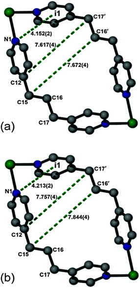 | ||
| Fig. 6 Perspective views of an isolated macrocyclic unit showing selected non-bonding distances at two different temperatures: (a) 100 K and (b) 260 K. | ||
The O–H⋯O hydrogen bonding interactions are sufficiently strong to preclude variation in the donor⋯acceptor distances with temperature (Table S4, ESI†).
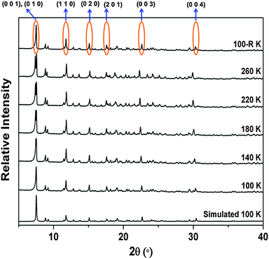
Variable temperature X-ray powder diffraction (VT-XRPD) was carried out to confirm the thermal expansion of the bulk material. Reflections corresponding to the Miller indices 00l shift towards lower 2θ (°) values with increasing temperature, confirming positive thermal expansion approximately along the c axis (along X3). Reflections with Miller indices hk0 show almost no shift with changing temperature (Fig. 8, Fig. S15 and S16, ESI†). Furthermore, the diffraction patterns also confirm reversibility of the thermal expansion phenomenon. The differential scanning calorimetric (DSC) thermogram of 1 precludes any possibility of a thermotropic phase transition (Fig. S17, ESI†) since no energetic events are observed during the thermal cycle (100–260 K).
To date, flexible materials that exhibit anisotropic thermal expansion behavior have undergone expansion (or contraction) along one axis with an associated compensation along the remaining two axes. These materials involve a ‘scissor/hinge’ like motion that includes thermal expansion (contraction) of helical chains, zigzag chains or grid-like networks in one direction with compensation along the other. For example, the helical hydrogen bonded networks of (S,S)-octa-3,5-diyn-2,7-diol previously reported3a by Barbour et al. undergoes large anisotropic expansion facilitated by a scissor-type motion. Similarly, the Zn-MOF recently reported by the same group exhibits guest-dependent anisotropic positive thermal expansion involving expansion of Zn⋯OH⋯Zn chains, thus resulting in large PTE along the c axis with associated compensatory NTE along the a and b axes.12 However, the co-existence of linear NTE, PTE and ZTE in a single MOF material owing to a combined stretching–tilting mechanism has not previously been observed, thus making this finding unique. In 1 the flexible moieties of the BPP units are responsible for the NTE observed along the principle axis X1 while the same components as part of the macrocycle are responsible for the PTE observed along the principle axis X3.
Moreover, if the thermo-responsive phenomenon occurs without loss of single crystal character, the mechanism can be understood by analysing subtle structural variations with changes in temperature. The elucidation of such data may lead to the development of new materials with practical applications.
We thank the National Research Foundation and Department of Science and Technology (SARCHI Program) for support of this work. PL also thanks the Claude Leon Foundation for financial support.
Notes and references
-
N. W. Ashcroft and N. D. Mermin, Solid State Physics, Holt, Rinehart & Winston, 1976 Search PubMed
.
-
R. S. Krishnan, R. Srinivasan and S. Devanarayanan, Thermal Expansion of Crystals, Pergamon, 1979 Search PubMed
.
-
(a) D. Das, T. Jacobs and L. J. Barbour, Nat. Mater., 2010, 9, 36–39 CrossRef CAS PubMed
; (b) A. D. Fortes, E. Suard and K. S. Knight, Science, 2011, 331, 742–746 CrossRef CAS PubMed
; (c) D. Das, T. Jacobs, A. Pietraszko and L. J. Barbour, Chem. Commun., 2011, 47, 6009–6011 RSC
.
-
(a) L. D. DeVries, P. M. Barron, E. P. Hurley, C. Hu and W. Choe, J. Am. Chem. Soc., 2011, 133, 14848–14851 CrossRef CAS PubMed
; (b) S. Henke, A. Schneemann and R. A. Fischer, Adv. Funct. Mater., 2013, 23, 5990–5996 CrossRef CAS
; (c) H.-L. Zhou, R.-B. Lin, C.-T. He, Y.-B. Zhang, N. Feng, Q. Wang, F. Deng, J.-P. Zhang and X.-M. Chen, Nat. Commun., 2013, 4, 2534 Search PubMed
.
-
(a) A. E. Phillips, G. J. Halder, K. W. Chapman, A. L. Goodwin and C. J. Kepert, J. Am. Chem. Soc., 2010, 132, 10–11 CrossRef CAS PubMed
; (b) A. L. Goodwin, B. J. Kennedy and C. J. Kepert, J. Am. Chem. Soc., 2009, 131, 6334–6335 CrossRef CAS PubMed
; (c) A. L. Goodwin, M. Calleja, M. J. Conterio, M. T. Dove, J. S. O. Evans, D. A. Keen, L. Peters and M. G. Tucker, Science, 2008, 319, 794–797 CrossRef CAS PubMed
.
-
(a) R. Banerjee, H. Furukawa, D. Britt, C. Knobler, M. O'Keeffe and O. M. Yaghi, J. Am. Chem. Soc., 2009, 131, 3875–3877 CrossRef CAS PubMed
; (b) J. J. Perry IV, J. A. Perman and M. J. Zaworotko, Chem. Soc. Rev., 2009, 38, 1400–1417 RSC
; (c) J. M. Ogborn, I. E. Collings, S. A. Moggach, A. L. Thompsona and A. L. Goodwin, Chem. Sci., 2012, 3, 3011–3017 RSC
.
-
(a) A. L. Goodwin and C. J. Kepert, Phys. Rev. B: Condens. Matter Mater. Phys., 2005, 71, 140301–140304 CrossRef
; (b) A. L. Goodwin, K. W. Chapman and C. J. Kepert, J. Am. Chem. Soc., 2005, 127, 17980–17981 CrossRef CAS PubMed
; (c) J. L. Korcok, M. L. Katz and D. L. Lenznott, J. Am. Chem. Soc., 2009, 131, 4866–4871 CrossRef CAS PubMed
.
-
(a) V. K. Peterson, G. J. Kearly, Y. Wu, A. J. Ramirez-Cuesta, E. Kemner and C. J. Kepert, Angew. Chem., Int. Ed., 2010, 49, 585–588 CrossRef CAS PubMed
; (b) Y. Wu, A. Kobayashi, G. J. Halder, V. K. Peterson, K. W. Chapman, N. Lock, P. D. Southon and C. J. Kepert, Angew. Chem., Int. Ed., 2008, 120, 9061–9064 CrossRef
.
-
(a) N. Lock, Y. Wu, M. Christensen, L. J. Cameron, V. K. Peterson, A. J. Bridgeman, C. J. Kepert and B. B. Iverson, J. Phys. Chem. C, 2010, 114, 16181–16186 CrossRef CAS
; (b) D. Dubbeldam, K. S. Walton, D. E. Ellis and R. Q. Snurr, Angew. Chem., Int. Ed., 2007, 46, 4496–4499 CrossRef CAS PubMed
.
-
(a) X. Song, Z. Sun, Q. Huang, M. Rettenmayr and X. Liu, Adv. Mater., 2011, 23, 4690–4694 CrossRef CAS PubMed
; (b) S. Margadonna, K. Prassides and A. N. Fitch, J. Am. Chem. Soc., 2004, 126, 15390–15391 CrossRef CAS PubMed
.
-
(a) R. I. Belousov and S. K. Filatov, Glass Phys. Chem., 2007, 33, 271–275 CrossRef CAS
; (b) M. J. Cliffe and A. L. Goodwin, J. Appl. Crystallogr., 2012, 45, 1321–1329 CrossRef CAS
; (c) The Win_strain program is unpublished but available for download from http://www.rossangel.com; (d) A. Marmier, Z. A. D. Lethbridge, R. I. Walton, C. W. Smith, S. C. Parker and K. E. Evans, Comput. Phys. Commun., 2010, 181, 2102–2115 CrossRef CAS PubMed
.
- I. Grobler, V. J. Smith, P. M. Bhatt, S. A. Herbert and L. J. Barbour, J. Am. Chem. Soc., 2013, 135, 6411–6414 CrossRef CAS PubMed
.
Footnote |
| † Electronic supplementary information (ESI) available: Synthetic procedure, thermal analysis, detailed crystallographic information, additional figures and an animation of the thermal expansion mechanism. CCDC 984355–984364. For ESI and crystallographic data in CIF or other electronic format see DOI: 10.1039/c4cc02634a |
| This journal is © The Royal Society of Chemistry 2014 |

