 Open Access Article
 This Open Access Article is licensed under a Creative Commons Attribution-Non Commercial 3.0 Unported Licence
A new approach to prepare nanoscopic rare earth metal fluorides: the fluorolytic sol–gel synthesis of ytterbium fluoride†
L.
Schmidt
,
A.
Dimitrov
and
E.
Kemnitz
*
Department of Chemistry, Humboldt-Universität zu Berlin, Brook-Taylor-Straße 2, 12489 Berlin, Germany. E-mail: erhard.kemnitz@chemie.hu-berlin.de
First published on 5th May 2014
Abstract
A new approach for the preparation of approx. 5 nm sized ytterbium fluoride nanoparticles based on the fluorolytic sol–gel route is reported. DLS, TEM, IR and XRD were used to characterize the particles as well as the aging behavior of the sols. Furthermore, a new YbIII complex was isolated from the precursor solution and characterized by X-ray single crystal structure determination.
New approaches to the treatment of dental caries have prompted the search for new restorative materials that can not only restore the decayed tooth but also inhibit the demineralization of tooth enamel (bacterial growth) and therefore prevent the recurrence of caries.1 For several years now fluoride has been well known for its effectiveness in caries prevention. A variety of cariostatic mechanisms of fluoride action are involved in order to reduce dental caries formation.2
Metal fluorides hold great promise in dentistry as inorganic fillers in dental composites providing mechanical strength and chemical stability, a decrease in solubility and therefore a long-term fluoride release.3,4 Additionally oxides, fluorides and carbonates of lanthanum, hafnium, strontium and ytterbium are added for radiopacity in order to guarantee a precise radiographic diagnosis of carious lesions adjacent to the filling material. For some years now, rare earth (RE) metal fluorides have been used as inorganic filling materials in dentistry due to their ability to increase the efficiency of X-ray contrast and at the same time to provide a long-term fluoride release.5 There has been growing interest in using nanoparticles in order to improve the above-mentioned properties. In general, nano-structured inorganic particles are claimed to act as antibacterial agents and improve the strength and mechanical properties of dental restorative materials.6,7 Usually, RE metal fluorides are incorporated as a powder into the dental material. The average primary particle sizes which are reported vary thereby being in the range of 30–700 nm. Many chemical synthesis techniques have been developed to prepare nanoscopic RE metal fluorides. Usually, nanoscopic RE fluorides are prepared by autoclaving RE precursors in the presence of fluorinating agents at higher temperatures (hydrothermal method),8 thermal decomposition of RE precursors (usually trifluoroacetates)9,10 or using ionic liquids.11 In recent years, the polyol-mediated synthesis12 and the OA/ionic liquid two-phase method13,14 have been developed to enable controllable synthesis of RE metal fluorides. Each of these methods has its own advantages and disadvantages depending on the requirements for nanomaterials. However, all these reported methods allow obtaining RE nanocrystalline fluorides as powder samples.
The fluorolytic sol–gel15,16 synthesis represents an easy and mild chemical route for the preparation of nanoscopic metal fluorides which are examined for their properties and applicability. In this communication we report for the first time the preparation of ytterbium(III) fluoride sols with homodispersed particles of approx. 5 nm via the fluorolytic sol–gel synthesis, the advantage of this method being easy access to even large amounts of these materials. Dynamic light scattering (DLS), high resolution transmission electron microscopy (HRTEM), infrared spectroscopy (IR) and X-ray powder diffraction (XRD) are used to characterize the final products.
The formation of ytterbium fluoride sols proceeds via the fluorolytic sol–gel synthesis. (Full experimental procedure is available in the ESI†) The anhydrous ytterbium acetate was converted into ytterbium(III)–acetate–trifluoroacetate to give a transparent precursor solution. It has to be noted that by using both the ytterbium acetate and ytterbium trifluoroacetate as precursors sedimentation of agglomerated particles is observed. Only by a modification of anhydrous ytterbium acetate with trifluoroacetic acid we obtained a suitable precursor for the preparation of nanoscopic particles. Thus, the initial precursor for the formation of the final product was obviously a new mixed acetate. Indeed, by evaporating the methanol and all volatiles, we obtained a solid which showed a new XRD powder pattern (Fig. S2, ESI†). No reflections of the former pure acetates were detected. The new compound can be re-crystallized from water keeping unchanged its XRD powder pattern. We were able to grow single crystals of the new compound, [(H2O)Yb(CF3COO)2(CH3COO)]n·n[CH3COOH] from water solutions and solved its solid state structure by X-ray single crystal analysis. It crystallizes in the triclinic space group P![[1 with combining macron]](https://www.rsc.org/images/entities/char_0031_0304.gif) with Z = 2. The X-ray structure of the new compound shows the composition of an ytterbium complex with acetato and trifluoroacetato ligands directly bound to YbIII, as expected. The crystallographic data reveal that YbIII atoms in the new complex [(H2O)Yb(CF3COO)2(CH3COO)]n·n[CH3COOH] (1) are connected through different acetato- and trifluoroacetato-bridging modes forming the catena structure of 1. The asymmetric unit contains one YbIII atom coordinated by eight oxygen atoms (σ8λ3-Yb) of three different ligands (acetato, trifluoroacetato and aqua) as well as one uncoordinated acetic acid molecule (Fig. 1(i)). Whereas the water is bound on YbIII “pure terminally” (O9), all coordinated acetates act as bridging ligands. Three symmetry-related YbIII atoms build up the basic two subunits of the structure, each comprised of two metal centers: two YbIII atoms are linked through four μ2-trifluoroacetato-bridges (O3, O4, O5, O6) forming a centrosymmetric binuclear unit with Yb⋯Yb distances of 4.4641(12) Å, nearly the same as in the well-known tris(trifluoroacetato) trihydrates of RE metals.17,18 The acetato ligand affects twofold the structural motif of 1: firstly, it acts with both oxygen atoms (O7, O8) as a bidentant ligand on each YbIII atom and secondly, it connects the former triflouroacetato-ytterbium-binuclear subunits to a polymeric chain via a μ-oxygen (O7), completing the 8-fold symmetry at each YbIII center by forming a new Yb–O–Yb–O-ring with Yb⋯Yb distances of 3.9518(11) Å. A similar four-membered structural fragment was also determined in the crystal structure of ytterbium triacetate tetrahydrate.19Fig. 1(ii) shows the extended fragment constructed from both binuclear entities as the main feature of the catena structure of 1. Note that due to the inversion center, the aqua ligands (O9) alternate their orientations (trans to each other) at the YbIII atoms of the polymeric chain.
with Z = 2. The X-ray structure of the new compound shows the composition of an ytterbium complex with acetato and trifluoroacetato ligands directly bound to YbIII, as expected. The crystallographic data reveal that YbIII atoms in the new complex [(H2O)Yb(CF3COO)2(CH3COO)]n·n[CH3COOH] (1) are connected through different acetato- and trifluoroacetato-bridging modes forming the catena structure of 1. The asymmetric unit contains one YbIII atom coordinated by eight oxygen atoms (σ8λ3-Yb) of three different ligands (acetato, trifluoroacetato and aqua) as well as one uncoordinated acetic acid molecule (Fig. 1(i)). Whereas the water is bound on YbIII “pure terminally” (O9), all coordinated acetates act as bridging ligands. Three symmetry-related YbIII atoms build up the basic two subunits of the structure, each comprised of two metal centers: two YbIII atoms are linked through four μ2-trifluoroacetato-bridges (O3, O4, O5, O6) forming a centrosymmetric binuclear unit with Yb⋯Yb distances of 4.4641(12) Å, nearly the same as in the well-known tris(trifluoroacetato) trihydrates of RE metals.17,18 The acetato ligand affects twofold the structural motif of 1: firstly, it acts with both oxygen atoms (O7, O8) as a bidentant ligand on each YbIII atom and secondly, it connects the former triflouroacetato-ytterbium-binuclear subunits to a polymeric chain via a μ-oxygen (O7), completing the 8-fold symmetry at each YbIII center by forming a new Yb–O–Yb–O-ring with Yb⋯Yb distances of 3.9518(11) Å. A similar four-membered structural fragment was also determined in the crystal structure of ytterbium triacetate tetrahydrate.19Fig. 1(ii) shows the extended fragment constructed from both binuclear entities as the main feature of the catena structure of 1. Note that due to the inversion center, the aqua ligands (O9) alternate their orientations (trans to each other) at the YbIII atoms of the polymeric chain.
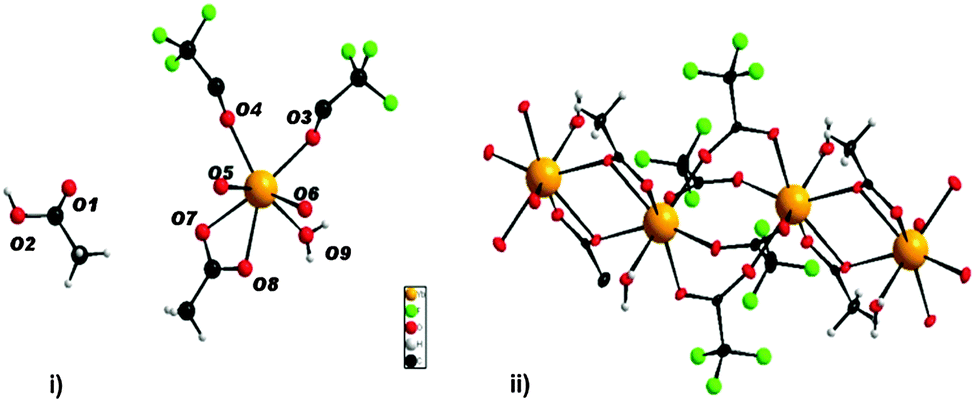 | ||
| Fig. 1 (i) Asymmetric unit representing complex 1 (ii) cut-out of the polymeric chain (CH3COOH– solvate molecules are omitted for clarity). | ||
After adding two equivalents of HF to the ytterbium precursor solution, a transparent sol of high concentration was formed. The resultant sol is stable for a few months and can be handled and stored in air. Just to mention, by adding 3 equivalents of HF, precipitation of agglomerates was observed. So, similar to the fluorolytic sol–gel synthesis of aluminium fluorides,20 operating substoichiometrically is recommended in order to obtain transparent sols. Thus, the final product can be described as YbF3−x(O2CCF3)x with x ∼ 1. The reaction pathway can be expressed as follows:

DLS was used to monitor the average hydrodynamic diameter of sol particles and to study the change in particles size with increasing concentration and increasing aging time of the sols. Fig. 2(i) shows the size distribution by intensity of sols with concentrations of 0.1 M, 0.5 M and 1 M. All three sols show a size distribution with two maxima. The 0.1 M sol having the lowest dynamic viscosity of 0.619 mPa s has the largest particles with a hydrodynamic diameter of approx. 10 and 220 nm. The sol of the highest concentration (1 M) has the highest viscosity (1.236 mPa s) with the particle size being smallest with approx. 3 and 70 nm. Since the size distribution by intensity is supposed to overestimate larger particles or agglomerates by a factor 106, Fig. 2(ii) presents the size distribution by volume with only one maximum. With increasing concentration the maxima shift to smaller values indicating the presence of particles with smaller hydrodynamic diameters. This tendency can be rationalized by the fact that nuclei formation proceeds faster than nuclei growth. Hence, the following particle growth is controlled by the restricted availability of molecular precursors that are faster consumed thus terminating any further mass transport. Maintaining a constant sol volume, the increase in viscosity can be attributed to different physical effects, which result from the relationship between particle size and concentration. Since DLS clearly indicates smaller particle formation due to the kinetic effect described above, the concentration of solid particles per volume fraction significantly increases. This causes strengthening of particle–particle interactions resulting in an increase in viscosity. Consequently, a larger amount of smaller particles influences the dynamic viscosity of sols. The 1 M sol does not only have a concentration of 10 times higher than the 0.1 M sol but it also exhibits particles with hydrodynamic diameters 3 times smaller. The volume fraction of the 1 M sol consists of a large amount of very small solid particles wherefore the resistance in movement and flow increases and viscosity increases significantly. The 0.5 M sol lies between the two above in terms of concentration, particle size and viscosity (0.804 mPa s). Thus, these results show concentration dependence of the hydrodynamic particle size of ytterbium fluoride sols.
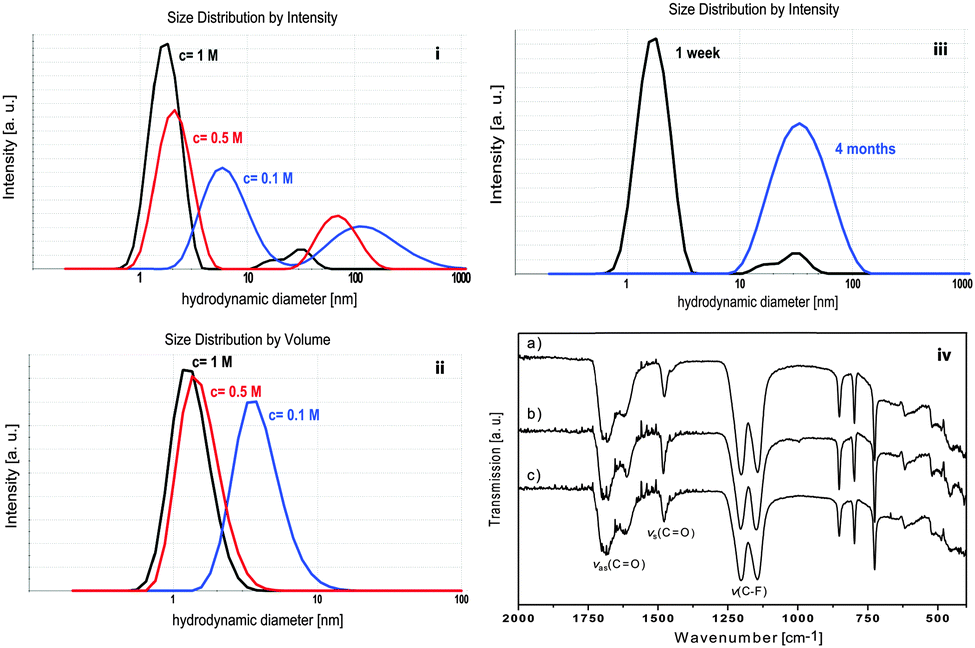 | ||
| Fig. 2 Size distribution by intensity (i) and volume (ii) of sols of different concentrations. (iii) DLS size distribution by intensity of a 1 M sol at different aging times. (iv) IR spectra of YbF3−x(O2CCF3)x xerogel obtained from a transparent 0.1 M sol (a) from a turbid 1 M sol (b) and from a precipitate after its sedimentation (c). | ||
The determination of crystallite sizes according the Scherrer equation would possibly support the results but the xerogels obtained from transparent sols are X-ray amorphous. The results from XRD measurements are presented in Fig. 3. The X-ray powder diffraction pattern of the YbF3−x(O2CCF3)x xerogel shows no reflections indicating that the xerogel obtained from the sol is X-ray amorphous. After calcining the xerogel at higher temperatures e.g. 300 °C and 500 °C narrow reflections of the orthorhombic YbF3 become visible, thus indicating the decomposition of the unreacted trifluoroacetate group at higher temperatures and formation of the stable YbF3.
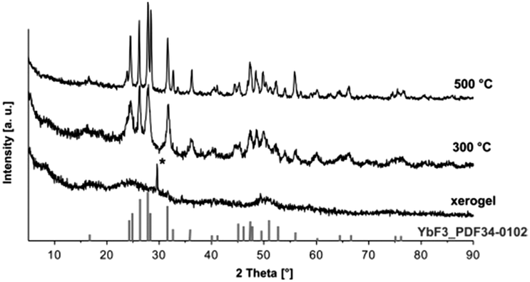 | ||
| Fig. 3 X-ray diffraction of the obtained xerogel at different calcination temperatures, reflection from the sample holder is marked with *. | ||
Additionally, to gain further information on particle size, morphology and crystallinity of nanoparticles, TEM investigations were performed. Apparently, the sol coating shows no particles by material contrast leading to the conclusion that an amorphous material is obtained and no particle size can be evaluated from the TEM image (Fig. S1, ESI†). The results are well in agreement with the XRD measurements (see Fig. 3).
Depending on the concentration the obtained sols age at different rates. While the low concentrated sol shows neither loss of transparency nor sol–gel transition over a period of 2 years, the sol with high concentration becomes turbid within months indicating the formation of larger agglomerates. This is demonstrated by DLS measurements (Fig. 2(iii)). The size distribution by intensity of a 1 week aged sol shows 2 maxima at 3 and 70 nm. The 4 month aged sol shows only one maximum at 70 nm. Immediately after fluorination 2 classes of particle size are present in the sol. Since the larger particles are overestimated, the particles of the smaller size of approx. 3 nm are in the majority. In the course of a few months the transparent sol becomes gradually more turbid. It can be assumed that during that time the small particles agglomerate to form larger units in order to lower the surface energy and to reach a thermodynamically stable state. After 4 months only larger agglomerates are present as only one maximum in the particle size distribution can be detected. As the aging proceeds, the sol becomes more turbid until a certain degree of turbidity is reached and a subsequent precipitation is observed after approx. 6 months. Meanwhile the 0.1 M does not show any signs of sol aging. Due to the difference in concentration the number of solid particles is lower. Also, DLS measurements show that the sol particles are larger than in the 1 M sol (see Fig. 2(i)). Hence, less particle–particle interactions occur, compared to sols of higher concentration, and therefore the agglomeration proceeds more slowly. Since ytterbium(III) compounds are paramagnetic, application of NMR techniques is inappropriate. In addition, XRD experiments are also not suitable for investigating structural changes as the xerogels are X-ray amorphous. For that reason IR spectroscopy was used to gain information on possible structural changes with increasing aging time. Fig. 2(iv) shows the IR spectra of an YbF3−x(O2CCF3)x xerogel obtained from a transparent 0.1 M sol, a xerogel obtained from a turbid 1 M sol and a precipitate after its sedimentation. The IR spectra exhibit the expected vibrations derived from unreacted TFA-groups in the samples. This is demonstrated by the (asymmetrical and symmetrical) stretching vibration of carbonyl groups at 1690–1612 cm−1 and at 1477 cm−1 and by the vibration of the C–F group at 1142–1202 cm−1. As no significant change is shown in the IR spectra, one can conclude that the turbidity and increase in particle size are a result of the proceeding agglomeration process which is caused by physical parameters mentioned above rather than by a change in the chemical structure of the particles.
In this study, the preparation of highly transparent ytterbium fluoride sols of high concentration and low viscosity by the fluorolytic sol–gel synthesis is presented for the first time. The particle size determined by DLS can be found in the lower nm range. Additionally, DLS studies show concentration dependence on particle size. Furthermore, DLS and IR spectroscopy were used to study the aging behavior of the sols. With increasing aging time, the sols become more turbid until sedimentation is observed. This process is based on the particles' tendency to agglomerate in order to reduce their surface energy and also depends on the concentration of the sols. The xerogel consists of agglomerated nanoparticles that remain amorphous at room temperature. XRD studies confirm the formation of YbF3 at higher temperatures. The new YbIII compound has been characterized giving structural information of the initial precursor. The main advantage of this precursor is its solubility and easy exclusion of water during the reaction. The presented fluorolytic sol–gel synthesis offers an easy and efficient access to nanoscopic ytterbium fluorides which, due to their nanoscopic size and amorphous character, can exhibit a high catalytic activity in selected reactions. Moreover, the sols are characterized by a high transparency, low viscosity and long-term stability and therefore are suitable for further processing in the fields of medicine, dentistry and optics. Especially the preparation of inorganic–organic nanocomposites is of great interest in material science. This work is currently ongoing in our group.
The authors would like to thank Beatrice Braun for support with the single crystal structure refinement and Holm Kirmse (Humboldt-Universität zu Berlin, Department of Physics) for TEM measurements. L. Schmidt is a member of the graduate school GRK 1582 “Fluorine as a Key Element” of DFG (Deutsche Forschungsgemeinschaft).
Notes and references
- A. Wiegand, W. Buchalla and T. Attin, Dent. Mater., 2007, 23, 343–362 CrossRef CAS PubMed.
- K. Rosin-Grget and I. Lincir, Coll. Antropol., 2001, 25, 703–712 CAS.
- G. Furtos, V. Cosma, C. Prejmerean, M. Moldovan, M. Brie, A. Colceriu, L. Vezsenyi, L. Silaghi-Dumitrescu and C. Sirbu, Mater. Sci. Eng., C, 2005, 25, 231–236 CrossRef PubMed.
- H. H. K. Xu, J. L. Moreau, L. Sun and L. C. Chow, Biomaterials, 2008, 29, 4261–4267 CrossRef CAS PubMed.
- T. C. S. Oliveira, E. Piva, F. B. Leal, M. D. Moncks and C. W. Raubach, Nano-Micro Lett., 2012, 4, 189–196 Search PubMed.
- I. Mohamed Hamouda, J. Biomed. Res., 2012, 26, 143–151 Search PubMed.
- H. H. K. Xu, J. L. Moreau, L. Sun and L. C. Chow, J. Dent. Res., 2010, 89, 739–745 CrossRef CAS PubMed.
- X. Wang, J. Zhuang, Q. Peng and Y. Li, Inorg. Chem., 2006, 45, 6661–6665 CrossRef CAS PubMed.
- Y.-P. Du, Y.-W. Zhang, L.-D. Sun and C.-H. Yan, Dalton Trans., 2009, 8574–8581 RSC.
- P. P. Fedorov, A. a. Luginina, S. V. Kuznetsov and V. V. Osiko, J. Fluorine Chem., 2011, 132, 1012–1039 CrossRef CAS PubMed.
- V. Bartůněk, J. Rak, Z. Sofer and V. Král, J. Fluorine Chem., 2013, 149, 13–17 CrossRef PubMed.
- M. Siemons, T. Weirich, J. Mayer and U. Simon, Z. Anorg. Allg. Chem., 2004, 630, 2083–2089 CrossRef CAS.
- M. He, P. Huang, C. Zhang, F. Chen, C. Wang, J. Ma, R. He and D. Cui, Chem. Commun., 2011, 47, 9510–9512 RSC.
- L. Pan, M. He, J. Ma, W. Tang, G. Gao, R. He, H. Su and D. Cui, Theranostics, 2013, 3, 210–222 CrossRef CAS PubMed.
- E. Kemnitz, U. Gross, S. Rüdiger and C. S. Shekar, Angew. Chem., Int. Ed., 2003, 42, 4251–4254 CrossRef CAS PubMed.
- S. Rüdiger and E. Kemnitz, Dalton Trans., 2008, 1117–1127 RSC.
- V. I. Belyi, A. A. Rastorguev, A. A. Remova, G. V. Romanenko and N. P. Sokolova, J. Struct. Chem., 2002, 43, 587–594 CrossRef CAS.
- C. J. Kepert, L. Wei-Min, P. C. Junk, B. W. Skelton and A. H. White, Aust. J. Chem., 1999, 52, 459–480 CrossRef.
- R. Vadura and J. Kvapil, Mater. Res. Bull., 1971, 6, 865–873 CrossRef CAS.
- C. Fritz, G. Scholz, M. Feist and E. Kemnitz, Dalton Trans., 2012, 41, 11351–11360 RSC.
Footnote |
| † Electronic supplementary information (ESI) available: Detailed experimental procedures, TEM image, XRD powder patterns and X-ray crystal structure solution of 1 (CIF). CCDC 996572. For ESI and crystallographic data in CIF or other electronic format see DOI: 10.1039/c4cc02626h |
| This journal is © The Royal Society of Chemistry 2014 |