 Open Access Article
Creative Commons Attribution 3.0 Unported Licence
Shuttle suppression in room temperature sodium–sulfur batteries using ion selective polymer membranes
I.
Bauer
,
M.
Kohl
,
H.
Althues
and
S.
Kaskel
*
Fraunhofer Institute for Material and Beam Technology (IWS), Winterbergstraße 28, D-01277 Dresden, Germany. E-mail: stefan.kaskel@iws.fraunhofer.de
First published on 3rd February 2014
Abstract
A sodiated Nafion-coating on a porous polypropylene backbone was used as a cation selective separator for room temperature sodium–sulfur batteries. The capacity of the cells after 20 cycles could be enhanced by 75% to 350 mA h gsulfur−1 using the new separator.
The ever growing demand of electrical devices and appliances has led to a rapid development in the field of electrical storage devices in the past years. Mainly lithium based battery systems fulfill these needs nowadays,1 however, lithium has a large drawback; it suffers from lack of natural deposits in contrast to sodium with a high natural abundance, namely 27 g per kg of earth crust (lithium 0.02 g kg−1) and 11 g l−1 in seawater, whereas lithium is practically non-existent in seawater (about 170 μg l−12).3,4 Sodium therefore has the potential to replace the more rare lithium.
However, sodium has a higher atomic weight, and thus lower specific capacity (1165 mA h g−1) than lithium (3862 mA h g−1) as well as a higher electrochemical standard potential of 0.33 V, leading to a decreased cell potential. As a result, lithium based technologies are likely better suited for high energy density applications whereas sodium-based battery technologies, due to the apparently lower raw material costs, are more suited for large-scale applications, like stationary electrical energy storage or power grid load leveling.5
In electrochemical cells sodium can be paired with intercalation compounds such as NaxCoO2,6 Na2MPO4F7 and NaNi0.5Mn0.5O2,8 as well as with the elements oxygen9 and sulfur.10 Sulfur as a cheap, non-toxic, naturally abundant and high capacity cathode material (1672 mA h g−1) has attracted much attention recently; on one hand in lithium–sulfur batteries11–15 and on the other hand in stationary high temperature sodium–sulfur batteries.5,16,17 High temperature sodium–sulfur batteries have been developed by NGK Insulators Ltd. and the Tokyo Electric Power Company (TEPCO) since the mid-1980s and consist of sodium and sulfur as negative and positive electrodes, respectively, and β′′-alumina as a solid electrolyte between the two electrodes.17 Due to the low sodium-ion conductivity of the β′′-alumina electrolyte, the cell has to be operated at a temperature of 300 °C in order to achieve a significant current flow of the battery, resulting in safety challenges related to molten sodium and increased operation costs.5,16,17
In the past years several efforts were made to assemble room-temperature sodium–sulfur batteries. Liquid organic electrolytes with porous separators were used, but they cause two main problems: cells do not reach a real cut-off voltage during charging and severe capacity loss occurs during cycling.18 Both effects are at least partly caused through one phenomenon, the polysulfide shuttle: the transfer of soluble polysulfide species from the cathode through the porous separator to the anode and the reduction of these polysulfides at the anode surface. The resulting formation of short chain polysulfides and sodium sulfide (Na2S) is a parasitic reaction which counteracts, during charging, the oxidation of polysulfides at the cathode. It is well described for the lithium–sulfur system.19,20 In order to prevent the polysulfide shuttle, ion conducting membranes between both electrodes can be applied. This was done with a PVdF/sodium triflate solid electrolyte in the past but strong capacity fading whilst cycling still occurred.21 Lower capacity losses were achieved with the use of a ceramic β′′-alumina solid electrolyte, similar to the one in commercial high-temperature sodium–sulfur batteries.10 However, ceramics are difficult to process, fragile to mechanical force and show low ionic conductivity at room temperature. Alternatives are cation selective organic membranes such as Nafion (sulfonated tetrafluoroethylene based fluoropolymer–copolymer). This material used as a free standing membrane has been shown in principle to be suitable for use in sodium-ion batteries.22 Nevertheless, free standing membranes are expensive and suffer from low ionic conductivity. In this regard, it would be more suitable to apply a thin layer of Nafion on a support structure to ensure structural stability, which so far has been reported only for the lithium–sulfur system.23,24
Here we present for the first time a room-temperature sodium–sulfur battery with a liquid electrolyte, a carbon–sulfur composite cathode and a polysulfide inhibiting separator consisting of a thin layer of Nafion hosted on a standard porous polypropylene separator with lower capacity fading than cells with a non-coated separator.
The coating of the porous polypropylene membrane with Nafion (referred to as a Nafion@separator) was performed by a drop coating procedure. Nafion dispersion (Nafion dispersion D2020, 20 wt% in alcohol/water base, Ion Power) was diluted to 3 wt% by addition of ethanol (Carl Roth, 99.8%) and subsequently homogenously spread on the porous polypropylene backbone. After drying at room temperature the coated membranes were sodiated (Na-Nafion@separator) in aqueous 1 M NaOH solution at 80 °C for 14 h. To remove excess salt, the coated and sodiated separator was treated at 80 °C for 1 h in water. Prior to cell assembly the separator sheets were dried at 80 °C for 60 min.
The sulfur–carbon composite was prepared by mixing sulfur and conductive carbon in a weight ratio of 1![[thin space (1/6-em)]](https://www.rsc.org/images/entities/char_2009.gif) :
:![[thin space (1/6-em)]](https://www.rsc.org/images/entities/char_2009.gif) 1 and melt was infiltrated at 155 °C for 12 h. The as-prepared sulfur–carbon composite was mixed with multi walled carbon nanotubes (MWCNT, Nanocyl NC7000, 90%) and poly(tetrafluoroethylene) (PTFE, Sigma Aldrich). The weight ratio of sulfur
1 and melt was infiltrated at 155 °C for 12 h. The as-prepared sulfur–carbon composite was mixed with multi walled carbon nanotubes (MWCNT, Nanocyl NC7000, 90%) and poly(tetrafluoroethylene) (PTFE, Sigma Aldrich). The weight ratio of sulfur![[thin space (1/6-em)]](https://www.rsc.org/images/entities/char_2009.gif) :
:![[thin space (1/6-em)]](https://www.rsc.org/images/entities/char_2009.gif) carbon
carbon![[thin space (1/6-em)]](https://www.rsc.org/images/entities/char_2009.gif) :
:![[thin space (1/6-em)]](https://www.rsc.org/images/entities/char_2009.gif) MWCNT
MWCNT![[thin space (1/6-em)]](https://www.rsc.org/images/entities/char_2009.gif) :
:![[thin space (1/6-em)]](https://www.rsc.org/images/entities/char_2009.gif) PTFE was 42.5
PTFE was 42.5![[thin space (1/6-em)]](https://www.rsc.org/images/entities/char_2009.gif) :
:![[thin space (1/6-em)]](https://www.rsc.org/images/entities/char_2009.gif) 42.5
42.5![[thin space (1/6-em)]](https://www.rsc.org/images/entities/char_2009.gif) :
:![[thin space (1/6-em)]](https://www.rsc.org/images/entities/char_2009.gif) 12
12![[thin space (1/6-em)]](https://www.rsc.org/images/entities/char_2009.gif) :
:![[thin space (1/6-em)]](https://www.rsc.org/images/entities/char_2009.gif) 3. Free standing cathode sheets were prepared from these raw materials by a dry processing method described elsewhere.25 For electrochemical investigations the cathode sheets were pressed onto carbon-coated (Electrodag EB-012) expanded aluminum (Benmetal, 99.5%). The thickness of the dry active layer was determined to be approx. 100 μm with a sulfur loading of about 2.0 mg cm−2.
3. Free standing cathode sheets were prepared from these raw materials by a dry processing method described elsewhere.25 For electrochemical investigations the cathode sheets were pressed onto carbon-coated (Electrodag EB-012) expanded aluminum (Benmetal, 99.5%). The thickness of the dry active layer was determined to be approx. 100 μm with a sulfur loading of about 2.0 mg cm−2.
Electrochemical measurements were performed in 2016 coin cells (MTI Corporation) using cathodes of 12 mm diameter. A metallic sodium ingot (Alfa Aesar, 98%) was calendered to a thickness of about 500 μm and disks with a diameter of 15 mm were used as anodes. The electrolyte consisted of 1 M sodium perchlorate (NaClO4, anhydrous, Alfa Aesar, 98.0–102.0%) dissolved in tetraethylene glycol dimethyl ether (TEGDME, Sigma Aldrich, ≥99%). To ensure a tight separation between anode and cathode space, the separator (19 mm diameter) was pressed between the bottom and the seal of the cell. All cells were assembled in an argon-filled glove box with an O2 and H2O content below 0.1 ppm. Cycling tests were performed on a BaSyTec CTS system between 1.2 and 2.5 V. Cyclic voltammetry measurements were carried out on an Ivium-n-stat potentiostat in the voltage range of 3.0–1.0 V. The maximum current was limited to 4 mA.
Attenuated total reflection (ATR) spectra were acquired using a Fourier transform infrared (FTIR) spectrometer Perkin Elmer Spectrum 2000 Golden Gate ATR for wavenumbers of 4000–600 cm−1. A JEOL JSM-6610LV was used for scanning electron microscope (SEM) measurements. SEM samples were sputtered with a few nanometers thick gold film to ensure electric conductivity.
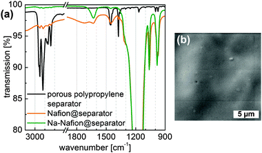
Infrared spectroscopy was used to evaluate the quality of the Nafion-coating as well as the conversion to the sodiated form of the Nafion coating (Fig. 1a). The nearly completely vanished CHx stretching vibration modes at 3000–2800 cm−1 of polypropylene for the (Na-)Nafion@separator samples indicate a dense film on the porous polypropylene membrane. The thickness of the coating could be calculated to be at least 0.5 μm due to the limited penetration depth of IR radiation for these wavelengths. According to Ostrowska et al. the disappearance of the peak at 1450 cm−1 and sharpening of the peak at around 1640 cm−1 are caused by exchange of protons with sodium ions in Nafion.26 SEM images of Nafion-coated polypropylene (Fig. 1b) substantiate the formation of a smooth and dense coating.
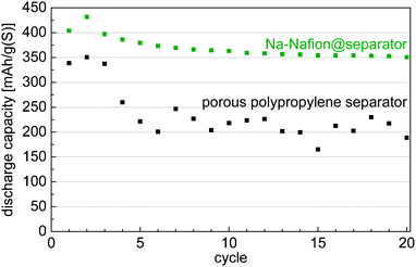
Application of the Na-Nafion@separator membrane enhances the sulfur utilization of the cells (Fig. 2). The capacity after the initial cycles increases by nearly 75% from about 200 mA h gsulfur−1 for the untreated separator to 350 mA h gsulfur−1 for the Na-Nafion@separator membrane. Moreover, cells with the Na-Nafion@separator show fewer fluctuations in capacity between the cycles than cells with the plain separator, because of lower polysulfide shuttle. The reactivity of polysulfides with the sodium anode changes during cycling because sodium with different surface areas is plated in each cycle. This change of surface area leads to varying shuttle intensity in cells with a plain separator and to fluctuating capacities.
 | ||
| Fig. 2 Discharge capacities of cells with the untreated separator and the Na-Nafion@separator at a C-rate of C/10 (approx. 0.4 mA cm−²). | ||
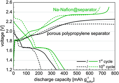
Analysis of the voltage profiles during charging shows that for cells with the untreated separator no voltage higher than 2.25 V was reached (Fig. 3). According to the electrochemical standard potentials a voltage of at least 2.23 V is necessary to obtain elemental sulfur in the sodium–sulfur cells, not considering any polarization effects, indicating that no elemental sulfur was formed. Substantiating this fact, the first discharge plateau was not well established for cells with the untreated separator, which originates from the reaction of elemental sulfur with long chain sodium polysulfides.10 In the case of the Na-Nafion@separator membrane a steep increase in the cut-off voltage of 2.5 V indicates the end of charging. Due to this fact and appearance of the first plateau at discharge, the formation of elemental sulfur can be assumed. The additional cycling capacity of cells with Na-Nafion@separator membranes (Fig. 2) can also be attributed to the presence of the first discharge plateau, since the capacity of the second plateau remains nearly unchanged. It is also to be noted that the discharge voltage is not lowered when using the Na-Nafion@separator indicating a sufficient ionic conductivity for the applied current of approx. 0.4 mA cm−2.
Reaching the charge cut off voltage in cells using the Na-Nafion@separator is a strong indicator for inhibiting the polysulfide transport through the Nafion-coated separator. The negatively charged sulfonic acid groups block the negatively charged polysulfides from passing the separator. As a result, the reduced polysulfide shuttle leads to an enhanced coulombic efficiency. The still relatively low coulombic efficiency of cells with the Na-Nafion@separator may be attributed to cracks in the coating or polysulfides present in molecular form which can penetrate the Nafion coating more easily.
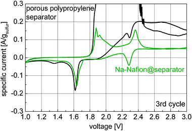
Cyclic voltammetry was used to gain information about the polysulfide shuttle and the species formed during cycling (Fig. 4).
 | ||
| Fig. 4 Cyclic voltammograms of cells with an untreated separator and a Na-Nafion@separator (scan speed 20 μV s−1, 3rd cycle is shown). | ||
The shuttle current in the voltage range of 2.6 to 3.0 V decreases from 0.12–0.2 A gsulfur−1 for the untreated porous polypropylene separator to about 0.05 A gsulfur−1 for the Na-Nafion@separator membrane. Additionally for charging voltages of 1.9 to 2.5 V high currents of 4 mA (maximum of the used measurement range) can be observed for the uncoated separator, indicating a very strong polysulfide shuttle. For discharge, the peaks at 2.3 V and 1.7–1.6 V can be attributed to the formation of polysulfides and solid sodium sulfide species respectively. At 1.4 V a small, broad peak is visible for the untreated separator which may have been caused by a solid state reaction to lower solid sodium sulfide species (Na2S2, Na2S).
For the first time Nafion was used as an ion-selective component in a separator for sodium–sulfur batteries demonstrating efficient operation at room temperature and good cycle stability. The sodiated Nafion coating on a porous polypropylene membrane combines both sufficient sodium ion conductivity and reduced polysulfide permeation. Cyclic voltammetry experiments show a decreased shuttle current of 0.05 A gsulfur−1 instead of 0.12–0.2 A gsulfur−1 for the untreated separator. Additionally, a significant increase in capacity of about 75% to 350 mA h gsulfur−1 after 20 cycles could be demonstrated using the sodiated Nafion-coated separator.
This research was supported by the Federal Ministry for the Environment, Nature Conservation and Nuclear Safety (BMU) through the project Batterie Stationär Sachsen (BaSta) and by the European Regional Development Fund (ERDF) through the project Composite S Power. The SEM image was taken by Jan Brückner.
Notes and references
- M. Armand and J.-M. Tarascon, Nature, 2008, 451, 652–657 CrossRef CAS PubMed.
- K. Schwochau, Inorganic Chemistry, Springer Berlin Heidelberg, Berlin, Heidelberg, 1984, vol. 124 Search PubMed.
- J.-M. Tarascon, Nat. Chem., 2010, 2, 510 CrossRef CAS PubMed.
- A. F. Holleman and N. Wiberg, Lehrbuch der Anorganischen Chemie, de Gruyter, Berlin, 102nd edn, 2007 Search PubMed.
- Z. Wen, J. Cao, Z. Gu, X. Xu, F. Zhang and Z. Lin, Solid State Ionics, 2008, 179, 1697–1701 CrossRef CAS PubMed.
- R. Berthelot, D. Carlier and C. Delmas, Nat. Mater., 2011, 10, 74–80 CrossRef CAS PubMed.
- N. Recham, J.-N. Chotard, L. Dupont, K. Djellab, M. Armand and J.-M. Tarascon, J. Electrochem. Soc., 2009, 156, A993 CrossRef CAS PubMed.
- S. Komaba, T. Nakayama, A. Ogata, T. Shimizu, C. Takei, S. Takada, A. Hokura and I. Nakai, ECS Transactions, ECS, 2009, pp. 43–55 Search PubMed.
- P. Hartmann, C. L. Bender, M. Vračar, A. K. Dürr, A. Garsuch, J. Janek and P. Adelhelm, Nat. Mater., 2013, 12, 228–232 CrossRef CAS PubMed.
- S. Wenzel, H. Metelmann, C. Raiß, A. K. Dürr, J. Janek and P. Adelhelm, J. Power Sources, 2013, 243, 758–765 CrossRef CAS PubMed.
- X. Ji, K. T. Lee and L. F. Nazar, Nat. Mater., 2009, 8, 500–506 CrossRef CAS PubMed.
- N. Jayaprakash, J. Shen, S. S. Moganty, A. Corona and L. A. Archer, Angew. Chem., Int. Ed., 2011, 50, 5904–5908 CrossRef CAS PubMed.
- P. Bruce and S. Freunberger, Nat. Mater., 2012, 11, 19–29 CrossRef CAS PubMed.
- J. Hassoun and B. Scrosati, Adv. Mater., 2010, 22, 5198–5201 CrossRef CAS PubMed.
- J. Brückner, S. Thieme, F. Böttger-Hiller, I. Bauer, H. T. Grossmann, P. Strubel, H. Althues, S. Spange and S. Kaskel, Adv. Funct. Mater., 2013 DOI:10.1002/adfm.201302169.
- A. Bito, in IEEE Power Engineering Society General Meeting, 2005, IEEE, 2005, pp. 2346–2349.
- T. Oshima, M. Kajita and A. Okuno, Int. J. Appl. Ceram. Technol., 2004, 1, 269–276 CrossRef CAS.
- H. Ryu, T. Kim, K. Kim, J.-H. Ahn, T. Nam, G. Wang and H.-J. Ahn, J. Power Sources, 2011, 196, 5186–5190 CrossRef CAS PubMed.
- J. Shim, K. A. Striebel and E. J. Cairns, J. Electrochem. Soc., 2002, 149, A1321–A1325 CrossRef CAS PubMed.
- Y. V. Mikhaylik and J. R. Akridge, J. Electrochem. Soc., 2004, 151, A1969–A1976 CrossRef CAS PubMed.
- J.-S. Kim, H.-J. Ahn, I.-P. Kim, K.-W. Kim, J.-H. Ahn, C.-W. Park and H.-S. Ryu, J. Solid State Electrochem., 2008, 12, 861–865 CrossRef CAS PubMed.
- C. Cao, W. Liu, L. Tan, X. Liao and L. Li, Chem. Commun., 2013, 49, 11740–11742 RSC.
- J. Huang, Q. Zhang, H. Peng, X.-Y. Liu, W.-Z. Qian and F. Wei, Energy Environ. Sci., 2013, 7, 347–353 Search PubMed.
- I. Bauer, S. Thieme, J. Brückner, H. Althues and S. Kaskel, J. Power Sources, 2014, 251, 417–422 CrossRef CAS PubMed.
- S. Thieme, J. Brückner, I. Bauer, M. Oschatz, L. Borchardt, H. Althues and S. Kaskel, J. Mater. Chem. A, 2013, 1, 9225–9234 CAS.
- J. Ostrowska and A. Narebska, Colloid Polym. Sci., 1983, 98, 93–98 Search PubMed.
| This journal is © The Royal Society of Chemistry 2014 |


