Conformational distribution of surface-adsorbed fibronectin molecules explored by single molecule localization microscopy†
E.
Klotzsch
ab,
I.
Schoen
a,
J.
Ries
c,
A.
Renn
d,
V.
Sandoghdar
e and
V.
Vogel
*a
aLaboratory of Applied Mechanobiology, Department of Health Sciences and Technology, ETH Zurich, Zurich, Switzerland. E-mail: viola.vogel@hest.ethz.ch
bInstitute for Applied Physics, Vienna University of Technology, Vienna, Austria
cEMBL, Heidelberg, Germany
dLaboratory of Physical Chemistry, ETH Zurich, Switzerland
eMax Planck Institute for the Science of Light, Erlangen, Germany
First published on 5th February 2014
Abstract
Adsorbed proteins that promote cell adhesion mediate the response of cells to biomaterials and scaffolds. As proteins undergo conformational changes upon surface adsorption, their functional display may be significantly affected by surface chemistry or solution conditions during the adsorption process. A high-resolution localization microscopy technique is extended here to probe the conformation of individual fibronectin (Fn) molecules at the glass–water interface under physiological buffer conditions. To map distances, four available cysteines located on the modules FnIII7 and FnIII15 of dimeric Fn were site-specifically labeled with Cy3B, and their relative positions were determined by stepwise photobleaching with nanometer precision. The four labels on single Fn molecules did not show a uniform or linear arrangement. The distances between label positions were distributed asymmetrically around 33 nm with a tail towards higher distances. Exposure of Fn to denaturing solution conditions during adsorption increased the average distances up to 43 nm for 4 M guanidinium HCl, while changing the solution conditions after the adsorption had no effect, indicating that the observed intra-molecular distances are locked-in during the adsorption process. Also surface coatings of different hydrophobicity altered the conformational distribution, shifting label distances from a median of 24 nm on hydrophilic to 49 nm on hydrophobic surfaces. These results further highlight that the conformation of macromolecules at interfaces depends on the adsorption history. While illustrated here for surface adsorbed Fn, the power of localization-based microscopy extends the repertoire of techniques to characterize biomolecules at interfaces.
1. Introduction
A central paradigm of structural biology is that the function of proteins is tightly coupled to their conformation. To determine the conformation of proteins in their natural context, methods are needed that can retrieve structural information in vivo in the presence of thousands of other proteins. Fluorescence-based techniques in combination with specific labeling strategies provide high contrast but have been traditionally limited to a resolution of ∼250 nm. A common approach to reveal the conformation of molecules by optical techniques relies on the attachment of fluorescent labels at specific positions within the molecule of interest. Typically two sites are labeled and the intra-molecular distance between labels is measured by FRET.1,2 A major breakthrough was the development of novel subdiffraction optical techniques3–6 that achieve nanometer precision and therefore have helped to elucidate the structure of supramolecular complexes such as microtubular networks,4 actin structures,6,7 focal adhesion clusters,6,8 and nuclear pore complexes.9,10 Only a few examples exist that explore the potential of these new techniques to study the conformations of single molecules. The iPALM technique was used to determine the vertical positions of N- or C-terminal labels on talin in cells and thereby revealed both the orientation and the extension of talin within the focal adhesion complex which consists of more than 80 different proteins.8 Moreover, it was shown by two-color colocalization of N- and C-terminal labels that the orientation of talin depends on cell contractility.11 The ability to measure distances between two identical labels by a localization method based on stepwise photobleaching has been used to characterize artificial DNA constructs12–14 and to explore the conformational heterogeneity of cadherin dimers.15 In this work we extend this approach to multiple labels and use the information about several intra-molecular distances to obtain a more comprehensive picture of the molecule. To introduce the technology, we studied the conformation of individual fibronectin (Fn) molecules adsorbed at a glass–water interface under in situ conditions.Dimeric Fn is a 440 kDa multimodular cell adhesion protein. Its 30 type III and 24 type I modules are each ∼3 nm in size and together with other domains they add up to an overall contour length of approx. ∼140 nm16,17 (Fig. 1A). Fn exposes two RGD binding sites that are recognized by integrins and is therefore commonly used to promote cell adhesion to surfaces. Earlier studies have found that the surface chemistry can influence the conformation of surface adsorbed Fn and the accessibility of binding sites which thus alters cell adhesion, proliferation, and differentiation processes.18,19 More recent studies have elucidated the role of surface chemistry-driven Fn fibrillogenesis on the cellular response.20,21 Since the functional aspects of fibronectin depend on its structural organization, it is essential to learn more about the Fn conformations at these interfaces.
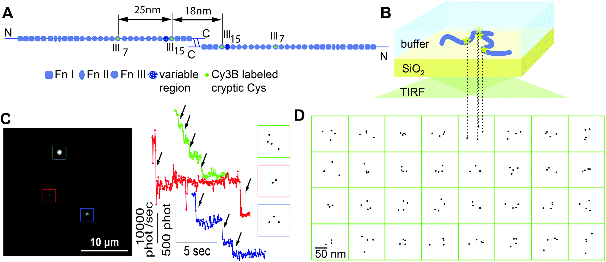 | ||
| Fig. 1 Conformation of single surface-adsorbed fibronectin molecules probed by localization microscopy. (A) Scheme of the modular structure of dimeric human plasma Fn. Fn molecules were labeled specifically with Cy3B at their 4 free cysteines which are located in modules FnIII7 and FnIII15 (green). The approximate distances between labeling sites are indicated for the case of a linear arrangement of the Fn modules with intact secondary structure, whereby each FnI/FnIII module has an approximate length of 3 nm. (B) Schematic of the 2D projection of adsorbed Fn as imaged in our set-up. Labeled Fn molecules were adsorbed to a glass coverslip from PBS and investigated using total internal reflection fluorescence (TIRF) microscopy. (C) Bleaching analysis. Individual spots in the image (left) showed four, three, or two steps in their intensity time traces (middle, arrows) and the respective positions of fluorophores within each molecule were reconstructed with nanometer precision (right; boxes depict 100 × 100 nm). The presence of molecules with only 2 or 3 fluorophores was due to either incomplete labeling or to already bleached fluorophores. (D) Reconstructed fluorophore positions of 32 Fn molecules that each showed four bleaching steps (boxes depict 150 nm × 150 nm). | ||
Fn is known to adopt a compact quaternary structure in physiological salt solutions as determined by sedimentation analysis22,23 and quasi elastic light scattering.24 Using fluorescence resonance energy transfer (FRET) as readout for the average Fn conformation, it was shown that Fn adsorbed to surfaces assumes a more open conformation where the dimer arms are partially separated from each other compared to the compact structure in solution.25 The contour of surface adsorbed Fn was imaged by transmission electron microscopy (TEM) sprayed on mica which showed distinct kinks in individual molecules that were suggested to correspond to regions of higher flexibility in the molecule.26,27 Furthermore, AFM on air-dried Fn on silica and mica surfaces revealed a more compact conformation for hydrophobic compared to hydrophilic surfaces.28 However, it is unclear to what extent spraying and drying procedures could have affected the conformation of Fn. It has been shown that the conformation of Fn is changing upon surface adsorption or during fibrillogenesis,25,29–32 and that its interaction with other molecules such as bacterial adhesion peptides,33,34 with albumin or the L8 monoclonal antibody,35 as well as the accessibility of buried cysteines29,36 were all sensitive to mechanical and chemical manipulation.
Fluorescence localization microscopy is well suited to retrieve conformational information on the expected length scale of about 10 to 100 nm and offers the advantage to investigate protein conformations in solution, thereby avoiding potential preparation artifacts. We exploited the presence of four free cysteines within native dimeric Fn. These cysteines, which are located on the modules FnIII7 and FnIII15, were site-specifically labeled with Cy3B maleimide (Fig. 1A). After adsorption, we reconstructed their positions within individual molecules using the stepwise bleaching analysis. Using a detailed analysis of the inter-label distance distributions, we find that the technique is indeed sensitive to probe a wide variety of Fn conformations, and that the conformations of surface-adsorbed Fn are determined by a combination of its conformation in solution and its interaction strength with model surfaces.
2. Experimental
2.1. Sample preparation
Fn was isolated from blood plasma following established procedures.30 Fn molecules were labeled with Cy3B maleimide using the same protocol as for labeling with Alexa dyes30 (see ESI section 1† about the choice of the chosen fluorophore). The labeling ratio was determined by measuring the absorption at 558 nm and 280 nm and resulted in 3.7 dyes per Fn dimer on average. The glass coverslips were pre-cleaned sequentially with aqueous detergent solution (0.5% Handy, MIFA, Frenkendorf, Switzerland), methanol, ethanol, and piranha acid assisted by ultra sonication, then washed with distilled water and blown dry. For varying the hydrophobicity of the surface, coverslips were (i) treated by an air-plasma (Harrick) for 5 min, (ii) baked in an oven at 400 °C for 4 hours, (iii) exposed to dimethyldichlorosilane (DMCS) vapor for 30 min, or (iv) incubated with octadecyltrichlorosilane (OTS; 10 mM in toluene) for 30 min. Static water contact angles were determined using a contact angle goniometer (Ramé-Hart Model 100). For adsorption to these substrates, Fn was diluted in phosphate buffered saline (PBS) to concentrations between 10 and 100 ng mL−1 and incubated for 15 min at room temperature. The surface coverage was less than 10 molecules per 10 × 10 μm. For additional information regarding sample preparation see ESI section 2.†2.2. TIRF microscopy
Our optical setup consisted of a home-built inverted microscope with total internal reflection (TIRF) illumination. The beam of a DPSS laser (Coherent DPSS, 532 nm, 100 mW) was expanded and focused through a wide-field lens (f = 300 mm) onto the back-focal plane of a high numerical aperture TIRF objective (Olympus NA 1.49, 60×, oil). The resulting illumination spot in the focal plane had a diameter of 45 μm, corresponding to a maximum intensity of up to 10 kW cm−2. The fluorescence light was separated from the excitation by a dichroic mirror (Chroma, z532/647rpc) and a longpass filter (Semrock, BLP01-532R) and focused by a 500 mm lens onto a back-illuminated EMCCD camera (Andor Ixon 897). The actual pixel size of 92 nm was determined by imaging a normalization grating (EM grid; mesh size 12.7 μm). Additional information on imaging can be found in the ESI sections 3 & 4.†2.3. Data analysis
Recorded movies were processed with home-written software written in Labview with NI Vision (National Instruments). For the selection of spots, the first 5 frames were averaged, high- and low-pass filtering was applied, and ROIs of 13 × 13 pixels around local maxima were selected. Intensity time traces were obtained from the total intensity of the central 9 × 9 pixels of the ROI in each frame. Pixel counts were converted into the number of detected photons using the camera gain value determined as previously described.37 A step finding routine38 was implemented to quantify the number and location of bleaching steps in each time trace. Traces where the plateau between two bleaching steps was shorter than 4 frames were discarded. The remaining traces with 2 to 4 steps were further analyzed using the high resolution stepwise photobleaching method.12,13 For each spot and step, four images recorded after and before the step were averaged and subtracted from each other. The difference images were fitted with a symmetric pixelized Gaussian using a Maximum Likelihood Estimator (MLE) for Poisson distributed data39 after adding a constant offset to guarantee positive photon counts. The MLE fitting was implemented by adapting Labview's in-built Levenberg-Marquardt nonlinear fitting routine according to published procedures.40 The location of the dye was obtained from the Gaussian center position. Further analysis of the data was done in Mathematica (Wolfram Research). A detailed description of the data acquisition and analysis can be found in ESI sections 5–12.†2.4. Precision of distance measurements
For stepwise photobleaching of Cy3B dyes on Fn, the typical number of collected photons per dye was ∼2000 (see Fig. 1C; summed over 4 frames) which limits the localization precision to ∼4–5 nm.41 The precision of the distance measurements thus is estimated as .14 This precision is much smaller than the peak position of inter-label distances around 30–50 nm (see Fig. 2–4) and thus should affect the observed distribution only to a minor extent. Furthermore, the accuracy of the technique was validated for measuring distances on an end-labeled DNA-helix, details can be found in ESI section 12.†
 | ||
| Fig. 2 Histogram of intra-molecular distances between the site specific labeling sites on FnIII7 and FnIII15 of single surface adsorbed dimeric fibronectin molecules that showed bleaching of either four fluorophores (red, n = 47), three fluorophores (green, n = 91) or two fluorophores (blue, n = 107), respectively. The good agreement between histograms indicates that the labeling probability of the 4 cysteines was random. Fn was adsorbed from PBS solution to pyrolytically cleaned glass at room temperature. | ||
 | ||
| Fig. 3 Distribution of intra-molecular distances in surface-adsorbed fibronectin for different solution conditions. Fn was adsorbed to pyrolytically cleaned coverslips from PBS solutions at room temperature with denaturant concentrations as indicated. (A) Dependence of intra-label distances of dimeric Fn on denaturant concentration during adsorption. Prior to the adsorption on the glass surface, Fn molecules were kept in phosphate buffered saline (PBS), PBS plus 2 M GdnHCl, or PBS plus 4 M GdnHCl for 10 min, respectively. The distance distributions were shifted towards higher distances and were broader for higher concentrations of the denaturant. Intra-label distributions had a median of 33.7 nm (N = 245) for PBS, 34.5 nm (N = 118) for 2 M GdnHCl and 43.2 nm (N = 105) for 4 M GdnHCl. The dashed line in the histogram for 4 M GdnHCl depicts the expected distance distribution for denatured fibronectin behaving as a worm-like chain (see Experimental section 2.6 and ESI section 13† for details). The maximum likelihood fit resulted in a persistence length of 8.5 ± 1.0 nm. (B) Dimeric Fn was adsorbed to glass surfaces from PBS. After obtaining the Fn intra-label distances the solution was exchanged to 4 M GdnHCl and incubated for 10 minutes before the same sample was measured in a different region of interest again. Intra-label distributions had a median of 28.5 nm (N = 98) and 27.5 nm (N = 98) before and after buffer exchange. (C) Normalized histograms for the intra-label distance of monomeric Fn adsorbed from PBS (red) or from PBS containing 4 M GdnHCl (blue). Intra-label distributions had a median of 17 nm (N = 77) and 38.2 nm (N = 97) for TCEP and TCEP + 4 M GdnHCl, respectively. The dashed line is the predicted distance distribution according to a worm-like chain model with a fitted persistence length of 7.4 ± 0.7 nm (see ESI section 13†). (D) Comparison of data from (A)–(C) represented as box-whisker plots. The line depicts the median, boxes represent upper/lower quartiles, and whiskers depict the 10–90% range. Statistical tests were performed using the Kolmogorov–Smirnov comparison (*p < 0.05; ***p < 0.001). | ||
 | ||
| Fig. 4 Distribution of intra-label distances of dimeric fibronectin for different surface modifications. Fn molecules were adsorbed from PBS buffer at room temperature to coverslips that were plasma cleaned, pyrolytically cleaned, coated with dimethyldichlorosilane (DMCS), or with octadecyltrichlorosilane (OTS). (A) Histograms and (B) box-whisker plots of the distance distributions between labeling sites. In (B), the line depicts the median, boxes represent upper/lower quartiles, and whiskers depict the 10–90% range. Statisticals test were performed using the Kolmogorov–Smirnov comparison (***p < 0.001; *p < 0.05). Intra-label distributions had a median of 24.1 nm (N = 587), 33.7 nm (N = 245), 51.4 nm (N = 554) and 48.7 nm (N = 127) for plasma cleaned, pyrolytically cleaned, DMCS and OTS treated surfaces, respectively. | ||
2.5. Statistics
To quantify the differences between measured distance distributions, we used a Kolmogorov–Smirnov comparison where the maximum difference between the cumulative distributions was calculated using an online script available at http://www.physics.csbsju.edu/stats/KS-test.html.2.6. Worm-like chain model
To estimate the expected distance distribution between labeling sites within denatured Fn at the glass–water interface, we hypothesized that Fn's polypeptide chain adopts a flattened geometry when interacting with the surface. Based on this assumption, the polypeptide chains between labeling sites were modeled as 2D (rather than 3D) wormlike chains42 with a segment length of 0.38 nm and the persistence length as a free fitting parameter.The number of amino acids (aa) between labeling sites is 750 aa for FnIII7–FnIII15 within a Fn monomer per arm and 840 aa for FnIII15–FnIII15 in dimeric Fn according to the published sequence (P02751, uniprot.org). As a consequence, 1590 aa are positioned between FnIII7 and FnIII15 and 2340 aa lie between FnIII7 and FnIII7 on different arms of dimeric Fn (see also Fig. 1A). Assuming that the modules between labeling sites are denatured, the distance probability distribution for the labels within monomeric Fn was calculated using eqn (3.2) from ref. 43 using 750 aa as contour length. In dimeric Fn, the FnIII15–FnIII15 and FnIII7–FnIII7 distances are present only once, whereas the inter- and intra-arm distances between FnIII7–FnIII15 are present twice each. Thus the cumulative distance probability distribution for dimeric Fn was calculated from the sum of the individual distributions of all possible fluorophore pairs. A detailed description of the 2D WLC model can be found in ESI section 13.†
3. Results
3.1. Localization of the specific label positions within surface-adsorbed Fn molecules
Fluorescently labeled Fn molecules were adsorbed from a dilute solution of phosphate buffered saline (PBS) at pH 7.4 to a pyrolytically cleaned glass coverslip (Fig. 1A and B). The density of adsorbed molecules was kept low to study the adsorption behavior of single Fn without the influence of lateral interactions with other Fn molecules, and to minimize the probability that the fluorescent spots of two molecules overlapped (Fig. 1C). Movies were recorded and the total intensity of each spot was analyzed over time (Fig. 1C). The fluorescence decayed in distinct steps and showed a maximum of up to four bleaching events. As 4 fluorophores are present per dimeric Fn molecule, we conclude that the fluorescent spots represented single dimeric Fn molecules.The localization analysis of the bleaching traces with 4 steps yielded patterns for the fluorophore positions that did not show a uniform or linear arrangement (Fig. 1D). The localization precision of the used technique was estimated to be around 4–5 nm (see the Experimental section and ESI†). If fluorophore patterns were to originate from a single well-defined conformation, the patterns could thus show a positional scattering of up to 10 nm between labels. However, the observed and much larger pattern variety cannot be explained by the limited measurement precision. We thus conclude that this variety reflects a broader distribution of single molecule conformations.
3.2. Distribution of inter-label distances
As a measure for the compactness of the adsorbed Fn molecule, the distances between the projected positions of the labeled cysteines within the Fn molecule were quantified, molecule by molecule. As the labeling sites are indistinguishable, all possible intra-molecular distances were combined and histograms were created for all positional patterns with four, three, or two fluorophores, respectively (Fig. 2). The histograms of label-distances showed a steep rise already at 10 nm, peaked at around 30 nm, and showed a tail towards distances of 80 nm. The largest part of the observed distance distribution correlates well with the expected distances between labeling sites in Fn. Within a straightened Fn dimer with intact secondary structure, the distances of labeling sites are in the range between 18 nm for the smallest distance between modules FnIII15 and FnIII15 and 68 nm for the largest possible distance between modules FnIII7 and FnIII7 (Fig. 1A). The observed distances below ∼20 nm can be explained when postulating the existence of kinks within the molecules. Distances above 70 nm are not explained by a tight ‘pearls-on-a-chain’ arrangement of modules with intact secondary structure and demand for additional extension of the molecule, as will be discussed later.The presence of patterns with less than four fluorophores was due to incomplete labeling or due to fluorophores that had already been bleached during the preparation procedure. The intra-molecular distances from positional patterns with two or three fluorophores resembled those of the completely labeled molecules (Fig. 2), as is expected for a statistical labeling of the four cysteines on FnIII7 and FnIII15 with equal probability. As the labeling sites are indistinguishable in our measurements, we combined the intra-molecular distances from different patterns for further analysis. For the comparison of different distributions, we represented the data also as box plots since the broad distributions did not show distinct peaks.
To investigate the distribution of distances along a single Fn molecule between modules FnIII7 and FnIII15, we used 50 mM tris(2-carboxyethyl)phosphine (TCEP) as a reducing agent to cleave the disulfide bonds that connect the monomers in the Fn dimer. As expected, the adsorbed Fn monomers only showed a maximum of two bleaching steps. The distance distribution had a median of 17 nm (Fig. 3C) which is significantly shorter than the ∼25 nm expected for a linear series of FnIII modules between the labeling sites (see Fig. 1A). This suggests that the monomer Fn arm can be bent between FnIII7 and FnIII15. Distances larger than 25 nm were observed for about 36% of all Fn monomers. This could be an indication for partially unfolded FnIII modules, or could be attributed to the so-called variable region in plasma Fn44,45 which lies in-between the two labeling sites on modules FnIII7 and FnIII15 (see Fig. 1A).
Comparing the data sets for monomeric and dimeric Fn, the distance distribution of monomeric Fn (Fig. 3C) overlapped with the shorter part of the distribution for dimeric Fn (Fig. 3A), whereas distances larger than >40 nm were extremely rare. This suggests that these larger distances in the dimer correspond to pairs of labeling sites positioned on adjacent Fn arms.
3.3. Conformation of surface-adsorbed fibronectin is sensitive to solution conditions during but not after adsorption
We next addressed the question of how chemical denaturing of dimeric Fn in solution changes its overall conformation upon surface adsorption. Fn was incubated for 10 minutes in PBS containing either 2 M or 4 M guanidinium hydrochloride (GdnHCl) prior to adsorption to pyrolytical cleaned glass. The intra-molecular distances between labels increased significantly under denaturing conditions, as did the width of the distributions (Fig. 3A) and the percentage of distances that are inconsistent with intact secondary structure. The median of intra-molecular distances increased from 33.7 nm for PBS to 34.5 nm for 2 M GdnHCl, and to 43.2 nm for 4 M GdnHCl. This trend is in agreement with intra-molecular FRET measurements that showed reduced FRET in denaturing solutions.25,30Denaturing of monomeric Fn in solution by 4 M GdnHCl led to an increase of the median, from 17 nm to 38.2 nm, and an approximately symmetric distribution around the peak position (Fig. 3C). As expected, the intra-label distances in the denatured Fn monomer approximately resembled the lower portion of the distance distribution of the denatured dimer.
To probe whether the Fn conformation can be altered after the physisorption process has taken place, Fn was first adsorbed from PBS to pyrolytically cleaned glass surfaces and the buffer was exchanged subsequently to PBS with 4 M GdnHCl and imaged after 10 minutes. To reduce contributions from variations between different samples, we measured the same sample at different positions before and after the solution exchange. Comparing the intra-molecular distances of molecules, no significant difference was found (Fig. 3B). We conclude that the already established interactions of adsorbed Fn molecules with the surface were strong enough to prevent major dimensional changes of the adsorbed molecules in the presence of denaturant.
3.4. Conformational distribution of surface-adsorbed fibronectin is sensitive to surface chemistry
Hydrophobicity has been used as an important parameter to modify adsorption of proteins to surfaces; however, in most cases the impact on the conformation of the adsorbent is not known. To investigate how the compactness of surface-adsorbed Fn molecules depends on surface treatments, we studied the adsorption of Fn to glass coverslips with varying hydrophobicity prepared by plasma cleaning, pyrolytic cleaning, silanization by dimethyldichlorosilane (DMCS) or octadecyltrichlorosilane (OTS).46The water contact angles of these surfaces ranged from less than 5° for the plasma cleaned surface, over an intermediate 40° for the pyrolytically cleaned sample, to 100° and 110° for DMCS and OTS treated coverslips, respectively.
Adsorption of dimeric Fn molecules from PBS onto hydrophilic surfaces yielded small distances whereas the interaction with hydrophobic surfaces resulted in larger distances but also a higher variability (Fig. 4). The more extended conformations on hydrophobic as compared to hydrophilic surfaces suggest stronger surface interactions with hydrophobic surfaces.
4. Discussion
Using a high-resolution fluorescence imaging method based on stepwise photobleaching, we could reconstruct fluorophore positions within individual Fn molecules with a precision of a few nanometers. This resolution is sufficient to deduce valuable information about the conformation and conformational distribution of large proteins. The localization of more than two labels allowed us to study their relative arrangements as a function of interfacial and environmental perturbations, and we illustrate how this gives valuable additional information compared to local distance measurements as obtained from two labels only. This extension of stepwise bleaching to multiple labels can be regarded as an intermediate case between distance measurements and direct imaging of the entire contour of single molecules.The projected positional patterns of the physisorbed Fn molecules revealed a broad spectrum of different conformations (Fig. 1D). This conformational variability is in agreement with previous investigations by TEM and AFM.26–28 The observed distances of 10–50 nm between the four cysteines within the Fn dimer (Fig. 2) and their non-linear arrangement (Fig. 1D) are consistent with previous estimates suggesting that an adsorbed dimeric Fn molecule has a total contour length of 120 nm, but only if we assume that kinks exist within the molecule, especially in the C-terminal region between the dimer arms.27,28,47
Despite the high variability of adsorbed plasma Fn, the analysis of intra-label distances (Fig. 2) provided a quantitative measure of molecular extension and revealed important information.
First, progressively larger populations of extended molecules were observed upon chemical denaturing with increasing concentration of GdnHCl, accompanied by a widening of the distributions (Fig. 3A). The diminished interaction between FnIII2 and FnIII14 that is essential for the globular state of Fn22 might contribute to the increased extension of the adsorbed molecules at 2 M GdnHCl, as well as a partial loss of secondary structure that increases to a total loss of secondary structure at 4 M GdnHCl, as has been shown previously by circular dichroism measurements and intra-molecular FRET.25,29–31,48 Denatured polypeptide chains have been shown to behave like worm-like chains (WLC),42,49 but it is unclear whether the adsorbed WLC has larger dimensions than the native adsorbed Fn molecules. Assuming that the polypeptide chain of denatured adsorbed Fn is confined to two dimensions, we modeled the intra-label segments of Fn as 2D worm-like chains43 (see ESI section 13†). The data of Fn monomers and Fn dimers at 4 M GdnHCl were well fitted by distance distributions of these 2D worm-like chains (dashed lines in Fig. 3A and C). The fitted persistence length equaled ∼8 nm for both monomeric and dimeric Fn. This agreement indicates that Fn segments between different labeling sites behave in a similar way as expected for unstructured polypeptide chains. The fitted persistence length for our 2D situation is an order of magnitude larger than that of a free polypeptide chain in 3D.42,49 This apparently drastic reduction in chain flexibility was surprising to us. We speculate that attractive interactions with the surface reduce the rotational degree of freedom along the WLC. In this view, the larger extension of denatured adsorbed Fn molecules could be explained by the larger number of possible surface interactions due to an increase in contour length upon denaturing.
Second, a large portion (64%) of monomeric Fn shows FnIII7–FnIII15 distances below 25 nm, indicating a bending which allows these two sites to come into closer proximity in a surface-adsorbed state and under physiological buffer conditions (Fig. 3C). The existence of a flexible hinge in this region is expected from the Fn sequence (i.e. the 6 aa linker between FnIII10 and FnIII11) and had previously also been concluded from TEM data,26 and from previous FRET analyses between these labeling sites.30,31
Third, Fn firmly interacts with the surface once it is adsorbed. This is seen from the fact that the overall dimensions of molecules adsorbed from physiological buffer to pyrolytically cleaned glass surfaces were hardly affected when the denaturant was added to the already adsorbed Fn molecules (Fig. 3B). This finding implies that the local interactions between parts of the Fn molecule and the surface that formed during adsorption from physiological buffer persist even when exposed to denaturing conditions. Consequently, the distances between pinning points are not altered such that even a potential unfolding of the molecules between these pinning points does not substantially increase the intra-label distances. Further experiments are needed to elucidate whether local secondary structure unfolding25 is contributing to these ‘pinning’ interactions.
Fourth, Fn adopted a more compact conformation on hydrophilic surfaces and an increasingly extended conformation on surfaces with increasing hydrophobicity (Fig. 4). This result is in agreement with experiments that used tryptophan fluorescence50 and FTIR-ATR51 to study Fn on hydrophilic germanium and hydrophobic self-assembled monolayers. These previous studies observed that Fn showed a higher loss of beta-sheet structure on hydrophobic surfaces than on hydrophilic surfaces. A study using fluorescence resonance energy transfer (FRET) between multiple, random labeling sites along the contour of Fn found higher FRET on fluorosilanized (hydrophobic) surfaces than on hydrophilic glass for sparsely labeled Fn molecules that are embedded in a densely packed protein monolayer.25 This finding indicates a more compact structure while our results showed an overall increase in the size of adsorbed Fn with increasing hydrophobicity (Fig. 4). It is unclear whether this apparent discrepancy originates from altered protein–surface interactions or is due to differences in the measurement techniques. On the one hand, monolayers of fluorocarbons have an interfacial dipole moment in contact with water that is opposite to that of hydrocarbons,52 which potentially affects protein orientation. Moreover, the previous FRET study used higher Fn surface densities that can lead to confinement of adsorbed molecules by neighbors and limits their extension, as has been shown for some other globular proteins.53,54 However, it is also possible that the fluorophores in Fn adopted a partially fixed orientation in contact with the surfaces31 or were partially quenched by interacting with the hydrophobic surface. A major advantage of the localization analysis is that it is far less sensitive to such changes than intensity-based FRET analysis. Electron microscopy (EM) found a more compact conformation of isolated Fn molecules on hydrophobic carbon and an elongated conformation on tissue culture polystyrene;55 however, the sample preparation in this study involved spraying of Fn and measuring in air. AFM studies indicated that Fn molecules are compact for hydrophobic and more spread out for hydrophilic surface treatments.28 But also here all measurements were done in air, and dewetting during the drying process might impact the conformation. AFM images of Fn adsorbed to polymeric scaffolds made of hydrophobic poly(ethyl acrylate) showed more extended and more fibrillar structures than Fn adsorbed on polymer substrates that included hydrophilic nanodomains of the co-polymer hydroxyethyl acrylate.20 In principle, these images agree with our data, but it is unclear to what extent the phase-segregated chemical patterning of the co-polymer influenced Fn's conformation.
What is the physiological significance of our findings? Different Fn conformations are known to alter interactions with different integrins as well as cellular functions such as adhesion, proliferation and differentiation.18,19 Antibody epitopes located on FnIII10 (which contains the RGD binding site) or on the flexible linker between FnIII10 and FnIII9 (which contains the synergy site) were more accessible when Fn was adsorbed to hydrophilic tissue culture polystyrene compared to Fn on untreated (hydrophobic) polystyrene, while the accessibility of other epitopes on other modules was affected to a minor extent.19 An increased exposure of specific adhesion motifs along FNIII7–FNIII10 and RGD site on more hydrophilic substrates was also observed for polymer substrates with varying ratios of hydrophobic to hydrophilic monomeric units.20 The same behavior has been observed with Fn adsorbed on self-assembled monolayers (SAMs) that were terminated by hydrophilic OH groups or hydrophobic CH3 groups.18 These surfaces have comparable termination chemistry and hydrophobicity as our plasma-cleaned and the DMCS-coated coverslips, respectively; we thus expect that our surface treatments affected Fn conformations in a similar manner. These Fn conformations tune the binding affinities for different integrins: the binding of α5β1 integrin which requires both the RGD sequence in FnIII10 and the synergy site in FnIII9![[thin space (1/6-em)]](https://www.rsc.org/images/entities/char_2009.gif) 56 was upregulated on hydrophilic substrates while binding of αVβ3 integrin which requires the RGD site alone was not affected by Fn conformation.18,19 These findings imply that the spatial arrangement of the FnIII9 and FnIII10 tandem which is necessary for high affinity binding to α5β1 integrin is at least partially compromised on hydrophobic substrates. This is in agreement with our finding of a more open Fn conformation on hydrophobic surfaces where the surface–protein interaction is strong and potentially leads to partial denaturing. The formation of α5β1-containing focal adhesions on Fn-coated hydrophilic substrates was shown to initiate FAK activation in a force-dependent manner and to act as a trigger for intracellular signaling, leading to the differentiation of C2C12 myoblasts selectively on these substrates.19 Substrate hydrophobicity thus is an important parameter that can be used to change Fn conformation and cellular response. However, the cellular behavior might also critically depend on the substrate's capability to induce Fn fibrillogenesis at higher densities.21
56 was upregulated on hydrophilic substrates while binding of αVβ3 integrin which requires the RGD site alone was not affected by Fn conformation.18,19 These findings imply that the spatial arrangement of the FnIII9 and FnIII10 tandem which is necessary for high affinity binding to α5β1 integrin is at least partially compromised on hydrophobic substrates. This is in agreement with our finding of a more open Fn conformation on hydrophobic surfaces where the surface–protein interaction is strong and potentially leads to partial denaturing. The formation of α5β1-containing focal adhesions on Fn-coated hydrophilic substrates was shown to initiate FAK activation in a force-dependent manner and to act as a trigger for intracellular signaling, leading to the differentiation of C2C12 myoblasts selectively on these substrates.19 Substrate hydrophobicity thus is an important parameter that can be used to change Fn conformation and cellular response. However, the cellular behavior might also critically depend on the substrate's capability to induce Fn fibrillogenesis at higher densities.21
Taken together, the conformation of the multimodular protein Fn on surfaces probed in water agrees well with models that have been developed for the adsorption of globular proteins, including their dependence on surface hydrophobicity and solution conditions.57 The contradictory findings in the literature highlight the need for novel characterization methods that are compatible with physiological conditions and are based on a readout that is robust against potential artifacts introduced by the proximity to interfaces.
5. Conclusions
Using Fn as a model system, we demonstrated here that fluorescence nanoscopy techniques are well suited to gain insights into the conformation of single macromolecules at interfaces. We therefore used the stepwise bleaching technique to analyze the arrangement of multiple specific labeling sites within Fn molecules. In principle, our approach can be extended to two or more spectrally different channels, as well as to 3-dimensional localization by iPALM58 or other 3D superresolution variants.59,60 Alternatively, techniques such as STORM,5 PAINT,61 or BALM62 could be used to image macromolecules that are labeled at (random) positions along their contour. In our opinion, the capability to analyze protein structure by fluorescence nanoscopy techniques in the presence of thousands of other (unlabeled) proteins makes these techniques attractive for a wide variety of questions in surface science, bioengineering and biophysics.Acknowledgements
We thank Gerhard J. Schütz for helpful comments on the manuscript. We gratefully acknowledge financial support from an ERC advanced grant number 233157 (VV), the Volkswagenstiftung (VV), the Deutsche Forschungsgemeinschaft (I.S.) and of the ETH Zurich. E.K. was partially supported by a FEBS Long-term Fellowship.Notes and references
- A. Muschielok, J. Andrecka, A. Jawhari, F. Brückner, P. Cramer and J. Michaelis, Nat. Methods, 2008, 5, 965–971 CrossRef CAS PubMed.
- R. Roy, S. Hohng and T. Ha, Nat. Methods, 2008, 5, 507–516 CrossRef CAS PubMed.
- S. W. Hell, Science, 2007, 316, 1153–1158 CrossRef CAS PubMed.
- M. Bates, B. Huang, G. T. Dempsey and X. Zhuang, Science, 2007, 317, 1749–1753 CrossRef CAS PubMed.
- M. J. Rust, M. Bates and X. Zhuang, Nat. Methods, 2006, 3, 793–796 CrossRef CAS PubMed.
- E. Betzig, G. H. Patterson, R. Sougrat, O. W. Lindwasser, S. Olenych, J. S. Bonifacino, M. W. Davidson, J. Lippincott-Schwartz and H. F. Hess, Science, 2006, 313, 1642–1645 CrossRef CAS PubMed.
- K. Xu, G. Zhong and X. Zhuang, Science, 2013, 339, 452–456 CrossRef CAS PubMed.
- P. Kanchanawong, G. Shtengel, A. M. Pasapera, E. B. Ramko, M. W. Davidson, H. F. Hess and C. M. Waterman, Nature, 2010, 468, 580–584 CrossRef CAS PubMed.
- A. Loeschberger, S. van de Linde, M.-C. Dabauvalle, B. Rieger, M. Heilemann, G. Krohne and M. Sauer, J. Cell Sci., 2012, 125, 570–575 CrossRef CAS PubMed.
- A. Szymborska, A. de Marco, N. Daigle, V. C. Cordes, J. A. G. Briggs and J. Ellenberg, Science, 2013, 341, 655–658 CrossRef CAS PubMed.
- F. Margadant, L. L. Chew, X. Hu, H. Yu, N. Bate, X. Zhang and M. Sheetz, PLoS Biol., 2011, 9, e1001223 CAS.
- M. P. Gordon, T. Ha and P. R. Selvin, Proc. Natl. Acad. Sci. U. S. A., 2004, 101, 6462 CrossRef CAS PubMed.
- X. Qu, Proc. Natl. Acad. Sci. U. S. A., 2004, 101, 11298–11303 CrossRef CAS PubMed.
- L. S. Churchman, H. Flyvbjerg and J. A. Spudich, Biophys. J., 2006, 90, 668–671 CrossRef CAS PubMed.
- A. Pertsinidis, Y. Zhang and S. Chu, Nature, 2010, 466, 647–651 CrossRef CAS PubMed.
- M. Baron, D. Norman, A. Willis and I. Campbell, Nature, 1990, 345, 642–646 CrossRef CAS PubMed.
- D. J. D. Leahy, I. I. Aukhil and H. P. H. Erickson, Cell, 1996, 84, 155–164 CrossRef CAS.
- B. G. Keselowsky, D. M. Collard and A. J. García, J. Biomed. Mater. Res., Part A, 2002, 66, 247–259 Search PubMed.
- A. J. García, M. D. Vega and D. Boettiger, Mol. Biol. Cell, 1999, 10, 785–798 CrossRef.
- A. J. Campillo-Fernández, R. E. Unger, K. Peters, S. Halstenberg, M. Santos, M. S. Sánchez, J. M. M. Dueñas, M. M. Pradas, J. L. G. Ribelles and C. J. Kirkpatrick, Tissue Eng. Part A, 2009, 15, 1331–1341 CrossRef PubMed.
- M. Salmerón-Sánchez, P. Rico, D. Moratal, T. T. Lee, J. E. Schwarzbauer and A. J. García, Biomaterials, 2011, 32, 2099–2105 CrossRef PubMed.
- K. J. K. Johnson, H. H. Sage, G. G. Briscoe and H. P. H. Erickson, J. Biol. Chem., 1999, 274, 15473–15479 CrossRef CAS PubMed.
- S. S. Alexander, G. Colonna and H. Edelhoch, J. Biol. Chem., 1979, 254, 1501–1505 CAS.
- E. C. Williams, P. A. Janmey, J. D. Ferry and D. F. Mosher, J. Biol. Chem., 1982, 257, 14973–14978 CAS.
- L. Baugh and V. Vogel, J. Biomed. Mater. Res., 2004, 69A, 525–534 CrossRef CAS PubMed.
- J. Engel, E. Odermatt, A. Engel, J. A. Madri, H. Furthmayr, H. Rohde and R. Timpl, J. Mol. Biol., 1981, 150, 97–120 CrossRef CAS.
- H. P. Erickson and N. A. Carrell, J. Biol. Chem., 1983, 258, 1–6 Search PubMed.
- M. Bergkvist, J. Carlsson and S. Oscarsson, J. Biomed. Mater. Res., Part A, 2003, 64A, 349–356 CrossRef CAS PubMed.
- E. Klotzsch, M. L. Smith, K. E. Kubow, S. Muntwyler, W. C. Little, F. Beyeler, D. Gourdon, B. J. Nelson and V. Vogel, Proc. Natl. Acad. Sci. U. S. A., 2009, 106, 18267–18272 CrossRef CAS PubMed.
- M. L. Smith, D. Gourdon, W. C. Little, K. E. Kubow, R. A. Eguiluz, S. Luna-Morris and V. Vogel, PLoS Biol., 2007, 5, e268 Search PubMed.
- M. Antia, L. D. Islas, D. A. Boness, G. Baneyx and V. Vogel, Biomaterials, 2006, 27, 679–690 CrossRef CAS PubMed.
- G. Baneyx, L. Baugh and V. Vogel, Proc. Natl. Acad. Sci. U. S. A., 2001, 98, 14464–14468 CrossRef CAS PubMed.
- M. Chabria, S. Hertig, M. L. Smith and V. Vogel, Nat. Commun., 2010, 1, 135–135 CrossRef PubMed.
- S. Hertig, M. Chabria and V. Vogel, Nano Lett., 2012, 12, 5162–5168 CrossRef CAS PubMed.
- W. C. Little, R. Schwartlander, M. L. Smith, D. Gourdon and V. Vogel, Nano Lett., 2009, 9, 4158–4158 CrossRef CAS PubMed.
- C. A. Lemmon, T. Ohashi and H. P. Erickson, J. Biol. Chem., 2011, 286, 26375–26382 CrossRef CAS PubMed.
- M. H. Ulbrich and E. Y. Isacoff, Nat. Methods, 2007, 4, 319–321 CAS.
- J. W. J. Kerssemakers, E. L. Munteanu, L. Laan, T. L. Noetzel, M. E. Janson and M. Dogterom, Nature, 2006, 442, 709–712 CrossRef CAS PubMed.
- C. S. Smith, N. Joseph, B. Rieger and K. A. Lidke, Nat. Methods, 2010, 7, 373–375 CrossRef CAS PubMed.
- T. A. Laurence and B. A. Chromy, Nat. Methods, 2010, 7, 338–339 CrossRef CAS PubMed.
- R. E. Thompson, D. R. Larson and W. W. Webb, Biophys. J., 2002, 82, 2775–2783 CrossRef CAS.
- H.-X. Zhou, J. Phys. Chem. B, 2001, 105, 6763–6766 CrossRef CAS.
- B. Hamprecht and H. Kleinert, Phys. Rev. E: Stat. Phys., Plasmas, Fluids, Relat. Interdiscip. Top., 2005, 71, 031803 CrossRef CAS.
- E. S. White, F. E. Baralle and A. F. Muro, J. Pathol., 2008, 216, 1–14 CrossRef CAS PubMed.
- J. E. Schwarzbauer, J. Cell Biol., 1989, 109, 3445–3453 CrossRef CAS.
- M. Raghavachari, H. Tsai, K. Kottke-Marchant and R. Marchant, Colloids Surf., B, 2000, 19, 315–324 CrossRef CAS.
- H. P. Erickson, N. Carrell and J. McDonagh, J. Cell Biol., 1981, 91, 673–678 CrossRef CAS.
- W. C. Little, M. L. Smith, U. Ebneter and V. Vogel, Matrix Biol., 2008, 27, 451–461 CrossRef CAS PubMed.
- M. Rief, Science, 1997, 276, 1109–1112 CrossRef CAS.
- G. Iwamoto, L. Winterton, R. Stoker, R. Vanwagenen, J. Andrade and D. Mosher, J. Colloid Interface Sci., 1985, 106, 459–464 CrossRef CAS.
- S. Cheng, K. Chittur, C. Sukenik, L. Culp and K. Lewandowska, J. Colloid Interface Sci., 1994, 162, 135–143 CrossRef CAS.
- V. Vogel and D. Möbius, J. Colloid Interface Sci., 1988, 126, 408–420 CrossRef CAS.
- H. Stutz, Electrophoresis, 2009, 30, 2032–2061 CrossRef CAS PubMed.
- C. F. Wertz and M. M. Santore, Langmuir, 1999, 15, 8884–8894 CrossRef CAS.
- T. M. Price, M. L. Rudee, M. Pierschbacher and E. Ruoslahti, Eur. J. Biochem., 1982, 129, 359–363 CrossRef CAS.
- S. K. Akiyama, S.-I. Aota and K. M. Yamada, Cell Adhes. Commun., 1995, 3, 13–25 CrossRef CAS.
- C. A. Haynes and W. Norde, J. Colloid Interface Sci., 1995, 169, 313–328 CrossRef CAS.
- G. Shtengel, J. A. Galbraith, C. G. Galbraith, J. Lippincott-Schwartz, J. M. Gillette, S. Manley, R. Sougrat, C. M. Waterman, P. Kanchanawong, M. W. Davidson, R. D. Fetter and H. F. Hess, Proc. Natl. Acad. Sci. U. S. A., 2009, 106, 3125–3130 CrossRef CAS PubMed.
- B. Huang, W. Wang, M. Bates and X. Zhuang, Science, 2008, 319, 810–813 CrossRef CAS PubMed.
- M. F. Juette, T. J. Gould, M. D. Lessard, M. J. Mlodzianoski, B. S. Nagpure, B. T. Bennett, S. T. Hess and J. Bewersdorf, Nat. Methods, 2008, 5, 527–529 CrossRef CAS PubMed.
- A. Sharonov and R. M. Hochstrasser, Proc. Natl. Acad. Sci. U. S. A., 2006, 103, 18911–18916 CrossRef CAS PubMed.
- I. Schoen, J. Ries, E. Klotzsch, H. Ewers and V. Vogel, Nano Lett., 2011, 11, 4008–4011 CrossRef CAS PubMed.
Footnote |
| † Electronic supplementary information (ESI) available: Fig. S2 showing the precision of distance measurements on DNA rulers and detailed materials and methods. See DOI: 10.1039/c3bm60262a |
| This journal is © The Royal Society of Chemistry 2014 |