 Open Access Article
NMR–DMF: a modular nuclear magnetic resonance–digital microfluidics system for biological assays†
Ka-Meng
Lei
a,
Pui-In
Mak
*a,
Man-Kay
Law
a and
Rui P.
Martins
ab
aState-Key Laboratory of Analog and Mixed-Signal VLSI and FST-ECE, University of Macau, China. E-mail: pimak@umac.mo
bInstituto Superior Técnico, University of Lisbon, Portugal
First published on 15th October 2014
Abstract
We present a modular nuclear magnetic resonance–digital microfluidics (NMR–DMF) system as a portable diagnostic platform for miniaturized biological assays. With increasing number of combinations between designed probes and a specific target, NMR has become an accurate and rapid assay tool, which is capable of detecting particular kinds of proteins, DNAs, bacteria and cells with a customized probe quantitatively. Traditional sample operation (e.g., manipulation and mixing) relied heavily on human efforts. We herein propose a modular NMR–DMF system to allow the electronic automation of multi-step reaction-screening protocols. A figure-8 shaped coil is proposed to enlarge the usable inner space of a portable magnet by 4.16 times, generating a radio frequency (RF) excitation field in the planar direction. By electronically managing the electro-wetting-on-dielectric (EWOD) effects over an electrode array, preloaded droplets with the inclusion of biological constituents and targets can be programmed to mix and be guided to the detection site (3.5 × 3.5 mm2) for high-sensitivity NMR screening (static B field: 0.46 T, RF field: 1.43 mT per ampere), with the result (voltage signal) displayed in real-time. To show the system's utility, automated real-time identification of 100 pM of avidin in a 14 μL droplet was achieved. The system shows promise as a robust and portable diagnostic device for a wide variety of biological analyses and screening applications.
1. Introduction
Portable point-of-care (POC) diagnostic tools have become an attractive approach for global healthcare, especially for under-developed countries where advanced low-cost diagnostic tools are very limited.1–6 In fact, for infectious diseases [e.g., human immunodeficiency virus (HIV) and tuberculosis], any retardation in diagnosis can worsen the situations at both individual and community levels.4,7A wide variety of point-of-care diagnosis tools have been available, such as the impedance and capacitance sensing,8–10 both of which rely on a pair of electrodes (transducers) to quantify the biological/chemical targets between them. With pre-designed probes and magnetic beads, magnetic sensing is another way to detect the targets.11,12 Bio-luminance detection is one more option to sense the amount of luminance emitted during the reaction of bioparticles such as pathogens and antigens.13,14 Apart from these methods, nuclear magnetic resonance (NMR) is considered as a new tool for diagnosis.15–17 Traditionally, NMR was used as an analytical tool for characterization of the structure of molecules and for chemical kinetics. Recent studies on NMR have successfully detected a number of biological targets, such as oligonucleotides,15 proteins,16,17Mycobacterium tuberculosis18 and bladder cancer cells, using a palm-sized permanent magnet.19 In addition, with the advances in micro-electronics, NMR circuitry can be miniaturized in size while upholding adequate sensitivity suitable for a wide variety of biological assays. The underlying principle of NMR detection is to sense the NMR signal from the samples, which are mixed with target-specific magnetic-nanoparticles. The presence of the target in the samples will lower the spin–spin relaxation time (T2), indicating the existence of the target rapidly in real-time.
One major challenge of micro-scale NMR is the operation of tiny samples beforehand, which can involve multi-step multi-site treatments. The samples under detection have to be mixed with the specific probes in one place and re-positioned to the sensing site inside the magnet for NMR. These procedures, regrettably, relied heavily on human efforts, degrading the throughput and consistency of diagnosis results while raising the chance of contamination. To address this issue, certain efforts have been undertaken to facilitate sample manipulation in NMR systems like capillary electrophoresis20 and microfluidic channels.17,21 Still, these methods involve several laboratory accessories (e.g., pumps and pressure generators) and fixed fluidic paths/pipes that have low portability and re-configurability.
In contrast, digital microfluidics (DMF) devices appear as a handy electronic-automated platform, allowing flexible droplet operations on a planar electrode array.22–26 By exploiting the principle of electrowetting-on-dielectric (EWOD) to modify the surface tension, droplets can be guided and transported freely over the electrodes. Unlike the channel microfluidic devices, the routing paths of droplets in DMF can be customized and re-programmed by a computer program, opening up much design flexibility to manage droplets such as transporting, mixing and splitting. In addition, as the DMF chip is planar, all droplets can be preloaded on a chip before routinely executing the reaction or screening, enhancing the consistency of the experiments.
Here we describe the first lab-on-a-chip module unifying nuclear magnetic resonance and digital microfluidics (NMR–DMF) with simple electronics and a portable magnet, allowing non-invasive magnetic resonance diagnosis atop the DMF chip in real-time. One of the key challenges of integrating NMR on DMF is the geometrical limitation of the portable magnet. We managed to overcome this by introducing a figure-8 shaped coil such that the magnet can be placed parallel to the DMF chip and RF coil to better use the inner space of the magnet. To demonstrate that the system is capable of performing biological assays in a fully autonomous fashion, biotinylated magnetic nanoparticles were selected as the probe to detect the existence of avidin in the droplet samples. Results showed that the system can transport and mix the samples and probes over the DMF chip successfully. We anticipate that this portable NMR–DMF system will be broadly applicable to small-sample biological analyses.
2. NMR–DMF system prototype
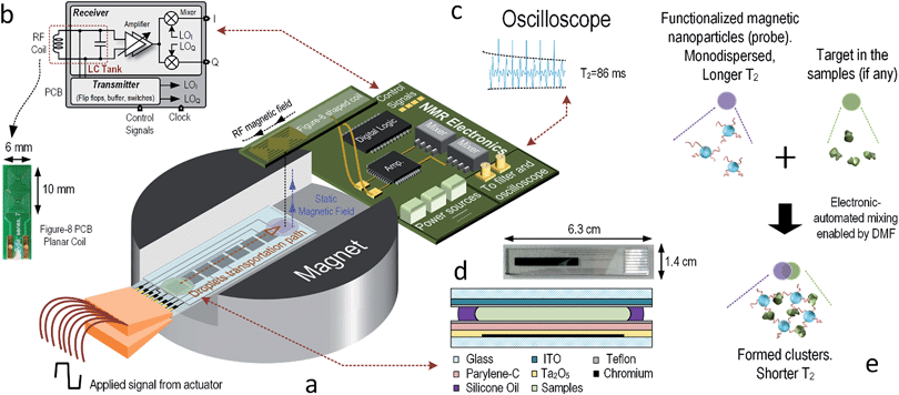
Fig. 1(a) shows the overview of the NMR–DMF system. It was designed to drive the droplets under detection and target-specific probes, if any, to the desired location for NMR assays. The movement of droplets is handled by an electrode array, which was fabricated on the glass substrate. The RF-coil functions as a transducer transforming the magnetic field to voltage (or vice versa). The electronics transmit the excitation signal to the RF-coil and receive the NMR signal from it. The results are collected by an oscilloscope in this prototype (for portability, by an analog-to-digital converter to interface with the computer). The relaxation times are derived by a software algorithm. The DMF platform and NMR coils are customized in size to befit the limited inner volume of the magnet; moreover, the design considerations of the system are introduced as follows.Nuclear magnetic resonance
 | (1) |
 | (2) |
To balance the system performance with its portability, a 0.5 T permanent magnet was chosen. It is 1.25 kg in weight and 1005 cm3 in volume. The corresponding fL of the hydrogen atom under this magnet strength is ∼21 MHz.
The schematic of the electronics is depicted in Fig. 1(b), which mainly consists of two paths: transmitter and receiver. Before the nuclear spins can induce signal to the coil, they have to be excited by the coil at fL. Since the Carr–Purcell–Meiboom–Gill (CPMG) sequence is applied, both in-phase (I) and quadrature (Q) waveforms are collected. By applying frequency division, a pair of equal-pulse-width I and Q signals can be generated under a clock-signal frequency 4 times that of the Larmor frequency. To prevent the SNR of the system from degrading by the flicker noise of the electronics, the clock frequency was chosen at 4(fL + fIF). Although the excitation frequency is shifted to fL + fIF instead of fL, the atoms can still be excited if fIF is small enough, which also facilitates the design of the electronics.19 Since the RF-coil serves both the transmitter and receiver, switches have to be used to isolate the excitation signal from leaking to the receiver. For the transmitter, output buffers were utilized to boost up the driving capability. The operating phases of the switches and buffers are controlled by a field-programmable gate array (FPGA).
The receiver can amplify the weak signal coupling from the RF-coils. The weak amplitude of the induced NMR signal is at a level of 100 nV to 40 μV.29 The first amplification is based on an LC tank to provide a passive gain Q to the signal, where Q is the quality factor of the RF-coil.19,29,30 The noise figure of the receiver will then be suppressed by Q, and the overall SNR will be increased according to eqn (2). The input impedance of the forefront amplifier should be adequately large to prevent its loading effects from the LC tank, which otherwise deteriorate the sensitivity. Obviously, the noise performance of the amplifier is decisive to the SNR of the receiver. In addition, as the signal amplitude is not consistent because of the uncertainties of the sample volume and biological constituents inside the samples, variable-gain amplifier is necessary for compensation.
After signal amplification, the signal is driven to the I and Q mixers for down-conversion to fIF, which also allows filtering of the high-frequency noise superimposed into the signal. Passive mixers befit this system as they generate less noise than its active counterpart. The resulting signals are then low-pass filtered and further amplified before driving into a digital oscilloscope [Fig. 1(c)] to reduce the uncertainty due to quantization error. According to eqn (2), the bandwidth of the filter should be set carefully to prevent excessive out-of-band noise. Finally the signals are collected for back-end processing such as I/Q demodulation and T2 derivation. The echoes' amplitude decays exponentially, and an algorithm written in MATLAB was built to derive and fit to this exponential curve:
 | (3) |
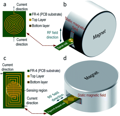
Typically, the planar coil is a circular spiral as shown in Fig. 2(a). The dominant magnetic field of this kind of RF-coil is in its axial direction. This spiral coil is common due to its high sensitivity, but the magnetic field from the RF-coil has to be orthogonal to the static magnetic field from the magnet, posing a physical limitation on the position of the coil. Illustrated in Fig. 2(b), the PCB coil has to be within the gap (12 mm) of the magnet, limiting the number of electrodes that can be integrated. One way to surmount this obstacle is to use a single-sided magnet with a surface-parallel magnetic field,31 where static and RF magnetic fields will be orthogonal to each other. However, this kind of magnet has to be customized, and the magnetic field is weaker when compared with the chosen (0.2–0.5 T). In fact, as another dimension of the gap is 50 mm in length, we make use of a figure-8 shaped coil to resolve this issue as shown in Fig. 2(c).32–34 Here, a square coil is utilized instead to enhance the magnetic field at the boundary. The figure-8 shape indicates that there are two coils with opposite axial magnetic field direction placed next to each other and connected in series. In this way, the magnetic field coupled between the centers of the two coils will be in-phase and constructively summed, as it is an effective sensing region of the coil.
With the same number of turns per spiral, the figure-8 shaped coil induces more thermal noise than the spiral coil since the length of the conductors is doubled. According to eqn (2), the SNR will be increased accordingly. However, it has been proven that the figure-8 shaped coil is less susceptible to environmental couplings (e.g., powerline cables, equipments and RF interference) since they appear as a common-mode noise.35–37 In addition, as depicted in Fig. 2(d), the RF-field direction of the sensitive region is parallel to the PCB. This indicates that the PCB-coil can be located horizontally with the gap of the magnet, enlarging the space 4.16 times for the DMF chip.
Digital microfluidics
The structure of a DMF platform is shown in Fig. 1(d), and it is composed by an electrode array. The electrodes are formed by chromium. ITO (Indium Tin Oxide) acts as a ground plane for the electric fields and is coated on a glass substrate. To integrate the NMR and DMF, the DMF chip is sized for inserting into the magnet for magnetizing the samples, and the coil is located over the samples for high-sensitivity sensing.
However, as the electrode (chromium) and ITO are made by conducting materials, the Q of the coil will be degraded when they are placed near the coils, due to the eddy currents formed in the conductors. The energy loss per cycle in the conductors by eddy currents (when the skin effect does not take place) is given as follows:38
 | (4) |
3. Materials and methods
Permanent magnets
Magnets PM-1055 was purchased from Metrolab (Switzerland). It has a nominal magnetic field of 0.5 T. The actual magnetic field was confirmed by Tesla Meter DTM-150 with probe LPT-130 from Group 3 Technology Ltd. (New Zealand) before the NMR experiment took place to ensure the applying frequency matches with fL given in eqn (1). In addition, since the magnet has a temperature coefficient of −1200 ppm K−1, the temperature of the testing environment has to be tracked to ensure the excitation frequency is not shifted from fL after temperature variation. This process was performed by a digital thermometer from Agilent (Santa Clara, CA).Electronics
The electronics detailed in ESI† was mounted onto a low-cost PCB. The control parts are linked to FPGA DE2 from Altera (San Jose, CA). The resulting signal from the PCB was filtered by the low-pass filter SR640 from Stanford Research Systems (Sunnyvale, CA). It filters out the high-frequency noise and offers extra signal gain. Finally, the signal was displayed on a digital oscilloscope DSO91304A from Agilent. To measure the overall signal gain, a sinusoidal test signal generated from signal generator E4436B, Agilent is injected into the receiver. The signal coming out from the low-pass filter is connected to a signal analyzer N9030A from Agilent.RF coils
The coil's layouts were drawn via Altium Designer Summer 09 (Australia). The turn spacing and width of the conductor in the coils are both 0.15 mm. The leads of the coils were drawn wide enough to minimize the loss. The thickness of copper in the PCB is ∼26 μm. The received coils were characterized by an impedance analyzer 4294A from Agilent. Four samples were measured for each type of coil to demonstrate the reproducibility. The performance and characteristics of the coil are studied by COMSOL™. The strength and direction of the magnetic fields are simulated by injecting a current of 1 A through the coil.Signal post-processing
The signals displayed on the oscilloscope were collected and analyzed by MATLAB (Natick, MA). The peak echo of the signals was detected and fit into the regression model to derive the T2 of the echo trains.Samples
De-ionized water was firstly tested to ensure the functionality of the system. Then, different concentrations of copper sulfate (CuSO4) diluted from CuSO4·5H2O were tested. Bio-assays were performed to ensure the practicability of the system. The bio-samples in this experiment were biotinylated iron nanoparticles and avidin from MicroMod (Germany). The size of the nanoparticles is 100 nm and the concentration of iron nanoparticles is 0.2 mM; moreover, the concentration of avidin is 1 mg mL−1.NMR settings
The sample volume for the NMR testing alone is 5 μL. The π/2 pulse widths for the coil was first estimated by calculation and then calibrated by observing the amplitude of the free induction decay of the NMR signals. Spacing between the echoes was set to 10 ms for the water and CuSO4 sample and 3 ms for magnetic particles. 30 echoes were collected for each NMR measurement, and each measurement was repeated 16 times to enhance the signal SNR. After each measurement, the system halted for 5 s before the next experiment to ensure that the atoms stop vibration and they have been magnetized stably by the magnet.Digital microfluidics chip
The ITO glasses were purchased from Huanan Technology Ltd. (China). Thickness of the overall glass is 0.5 mm. The pattern of the electrode was drawn in AutoCad (San Rafael, CA). The process of fabrication of the DMF platform is similar to the one stated before.25 The volume of liquid under testing per electrode (without mixing) is 7 μL. The electrodes were driven by a square wave with a peak-to-peak voltage of 40 V and a frequency of 1 kHz. The size of the electrodes is 3.5 × 3.5 mm2, and the gap between the top and bottom planes is 0.45 mm.4. Experiment and results
Magnets
To approximately locate the Larmor frequency of the hydrogen atoms, the magnet's field strength was first measured. The magnetic field at the center of the magnet is around 0.4615 T at 20 °C, which corresponds to a fL of 19.65 MHz.RF coils
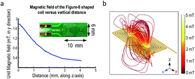
Several figure-8 shaped coils were optimized in COMSOL with a three-dimensional model before fabrication to determine the required number of turns. The fabricated coils were measured with an impedance analyzer and compared with the simulations to confirm the parameters. Table 1 shows two sets of parameters for the coil with 14 and 18 turns. The difference between the simulation and measurement results is sufficiently small (<7%). Such error could be originated from the leads of the coils in the measurements, coarse meshing in 3-dimensional simulation and the thickness variation of PCB copper traces. Nonetheless, the accuracy is adequate here as only the trend and magnetic field direction are decisive. This also offers a systematic study of the RF-coils when compared to the solenoid and saddle-shaped coils. Another advantage of the PCB coils is the reproducibility. From Table 1, the reproducibility of the PCB coils was adequately high as the standard deviations are <3% of the nominal values. This feature makes PCB coils attractive, as the fabrication only relies on machines, minimizing the variation between the same style of coils. The magnetic field strengths of figure-8 shaped coils versus vertical distance were simulated in Fig. 3(a). The magnetic field decays along the z-axis as expected. Thus, to maximize the sensitivity, the samples under test should be close to the coil's surface according to eqn (2). The unit magnetic field strength is 1.8 mT adequate for our system.| Turns | Resistance | Inductance | Quality factor |
|---|---|---|---|
| 14 (Sim.) | 1.44 Ω | 347.80 nH | 30.29 |
| 14 (Meas.) | 1.52 ± 0.04 Ω | 373.4 ± 2.7 nH | 31.0 ± 0.6 |
| 18 (Sim.) | 2.39 Ω | 646.58 nH | 34.01 |
| 18 (Meas.) | 2.48 ± 0.03 Ω | 687.0 ± 4.4 nH | 34.8 ± 0.3 |
Commercial tesla meter (e.g., DTM-150) can only measure AC magnetic field up to 3 kHz. Thus, only simulation results are presented to demonstrate the magnetic field direction of the figure-8 shaped coil under unit current injection. The magnetic-field profile of the 14-turn coil is plotted in Fig. 3(b), where the magnetic flux lines between the two coils align with the y-direction (i.e., parallel to the PCB surface).
Electronics
The measured gain of the mixer is 95.7 dB within 5 kHz of IF for the receiver. The output signal of the system with a 100 nV sinusoidal input is 30 dB above the noise floor, and thus it can detect a signal amplitude down to 100 nV. Data about the electronics measurement can be found in the ESI text and Fig. S1 and S2.†NMR systems
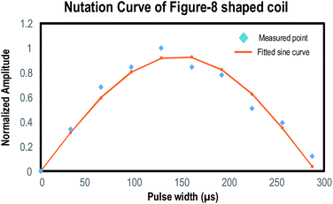
The pulse width of the figure-8 shaped coil was determined by varying the RF excitation pulse duration and observing the corresponding NMR signal. Fig. 4 shows the plot of such a nutation curve. The π/2 pulse for the 14-turn figure-8 shaped coil is estimated as 144 μs.Before integration of the NMR–DMF system, the NMR part was tested separately to verify its own functionality. According to the study, CuSO4 will affect the T2 of water.39,40 CuSO4 with different concentrations was prepared for the experiment. A 14-turn figure-8 shaped coil was selected for the NMR system.
Fig. 5(a) shows the received NMR signal of water from the figure-8 shaped coil. T2 derived by the algorithm is 343.6 ms. The glitches appearing between the echoes correspond to the excitation signal. They can be prevented by adding switches at the receiver front-end. Yet, since this will contribute with noise to the signal, they are left together with the echoes. Nevertheless, it will not affect the derivation of T2 since the algorithm will ignore the excitation signal. Moreover, the amplitude of the first echo is smaller when compared to the second and third echoes. This is caused by the superposition of different coherence pathways.41,42 Since the first echo is severely interrupted by this effect, leading to an amplitude smaller than expected, it will be excluded from the curve fitting algorithm to exclude the error.
The relation between the concentrations of CuSO4 and T2 was depicted in Fig. 5(b). 1/T2 is increased linearly with the concentration of CuSO4 (0.9866 mM−1 s−1).
Digital microfluidics chip
The thickness of the coated ITO can be determined by eqn (4). The magnetic energy generated from the 14-turn figure-8 shaped coil unit current is 144 nW. In order to preserve the quality factor of the coil, the thickness of the ITO coating should be evaluated. Fig. 6 shows the eddy current loss on the ITO generated by a unit current passing through the 14-turn figure-8 shaped coil against the ITO thickness. The eddy current loss should be diminished by less than 0.5% of the magnetic energy generated by the coil, which was marked on Fig. 6. The thickness is limited to 80 nm, which is equivalent to a sheet resistance of 12.5 Ω sq−1. ITO with sheet resistance of 100 Ω sq−1 was chosen for the system.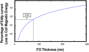 | ||
| Fig. 6 Percentage of Eddy current loss generated by the 14-turn figure-8 shaped coil to coil magnetic energy against the thickness of the ITO glass. The figure was plotted based on (4) with f = 20 MHz, ρ = 1 × 10⁻⁶ Ωm, A = 40 mm × 24 mm, which is 4 times the dimension of the figure-8 shaped coil. BRF is the magnetic field on the ITO. For accurate prediction, BRF should vary according to the relative position of the ITO compared to the coil. Here, only the peak magnetic field at the position of ITO (which is 1.5 mT from Fig. 3) is substituted. The dotted line shows 0.5% level and corresponds to the ITO thickness of 80 nm fr. | ||
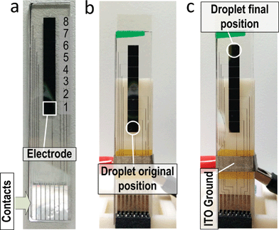
Fig. 7(a) shows the fabricated DMF chip. It consists of only 8 electrodes in a row for this prototype, and thus only one assay can be performed each time. Yet, this system can still demonstrate the idea of integrating NMR assays with the DMF platform. Fig. 7(b) and (c) show the original and final positions of the droplet. The droplet was transported from electrode no. 1 to no. 8, which is the NMR sensing site, by applying a signal on the electrode properly. The velocity of the droplets is ∼1.8 mm s−1. No obvious distinction of droplet movement was observed with and without a strong magnetic field, as expected, since the DMF works with the electric field for droplet manipulation.
Nuclear magnetic resonance on digital microfluidics chip
The proposed system integrates two core technologies: NMR and DMF. Integration with the DMF system can enable NMR to be performed in a more automatic and controllable way. Related image of the prototype and detailed testing result from water can be found in the ESI (Fig. S3†).For biological assays, the NMR–DMF system was operated to test the presence of avidin in the water sample using biotinylated magnetic nanoparticles as a probe.17,19 When avidin is absent from the samples, the biotinylated nanoparticles will stay monodispersed. Yet, if avidin exists, avidin and biotin will form rigid bonding, and the nanoparticles will aggregate and form large clusters. These clusters will perturb the neighbouring magnetic field and concomitantly decrease the T2 of the protons (i.e. decay faster), and thus the NMR system can detect the existence of avidin in real time. The concentration of biotinylated iron nanoparticle should be well designed. Excessive amount of iron nanoparticles will diminish the echoes' amplitude rapidly (low T2) and result in difficulty in acquiring the NMR signal. Detailed relationship between concentration of Iron nanoparticle and the limit of detection of avidin can be found elsewhere.17
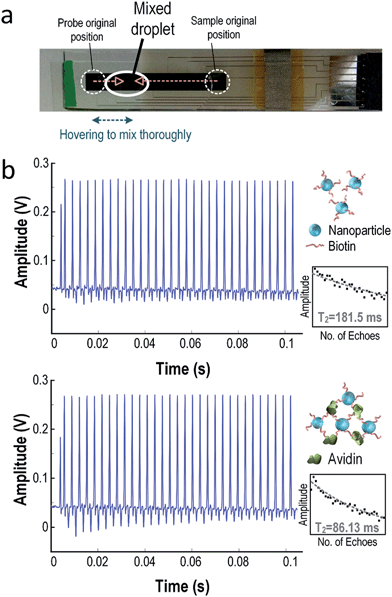
The sample under assay was placed at electrode no. 1 and the probe (droplets with nanoparticles) was placed at electrode no. 8. These two droplets will combine together at electrode no. 7 to form a larger droplet, as shown in Fig. 8(a). To ensure the droplet mixed thoroughly, it was shuffled between electrode no. 6 and no. 8 several times. Then, the droplet was moved to electrode no. 8 for NMR sensing.
Fig. 8(b) shows the received NMR signal with and without avidin. Without avidin in the sample (i.e. sample only contains water), T2 of the droplets is 181.5 ms. When avidin presents in the target droplet, it will bind to the biotin and form a larger cluster. Consequently, T2 of the droplets will be decreased to 86.13 ms with ΔT2 of −52.55%. The error in T2 of the NMR signals will decrease proportionally to the concentration of the targets in the samples, as suggested in previous research.17 These results show that the NMR–DMF platform can successfully detect the existence of a specific target in the samples in a fully automatic manner. The results promise that this system is a low-cost NMR-based diagnostic tool with high portability and electronic automation.
5. Discussion
Interference from silicone oil
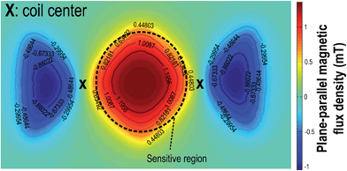
Surrounding the droplet samples by silicone oil is common in DMF to lower the required driving voltage and prevent sample vaporization. However, as silicone oil also contains hydrogen atoms, it will produce NMR signals, and their T2 is comparable to water (oil: 314.5 ms), affecting the sensitivity. To prevent the interference from silicone oil, the figure-8 shaped coil should be designed such that the sensitive region is all covered by the droplets. The sensitive region is midway to the two coils (Fig. 9) that jointly generate an adequate plane-parallel magnetic flux. Outside the region, the magnetic flux is smaller than half of its peak value, making the NMR signal weak enough, and thus it can be neglected. As a consequence, the assay location of the sample should be well-monitored by the DMF chip under real-time feedback control25 and has a surface area covering the sensitive region such that the silicone oil cannot affect the result, and the position error becomes more tolerable. Here, the sensitive region of a 14-turn figure-8 shaped coil has a diameter of 4.2 mm, which is fully covered by the droplet having a diameter of 6.3 mm.Potential applications
Unlike the spiral coil, the figure-8 shaped coil is capable of generating a plane-parallel RF-field, making it a powerful tool to be integrated with the planar DMF chip. A wide variety of applications can be considered over the NMR–DMF system. Simultaneous detection of multiple biomarkers in a sample is crucial in bio-assays.43 This system can perform NMR sensing on different sites simultaneously with multiple figure-8 shaped coils since the space available inside the magnet is enlarged. This can deliver a higher throughput which is suitable for drug screening.Other potential applications include cell incubation and detection in DMF platform, which is getting more attractive in recent years.24,44–51 With the confirmation that DMF has a negligible effect on the vitality and characteristics of the cells,24,52 it is favorable for operation with mass-limited cell samples. Typical cell characteristic assays on DMF include absorbance test,23 fluorescence,24,49 surface plasmon resonance53 and impedance sensing.54 These methods either require bench-top equipment (fluorescence, surface plasmon resonance), which have limited sensitivity (absorbance test) or are non-specific (impedance sensing). On the other hand, NMR could be more promising for cell targeting and quantitative analysis, including cancer cells for early cancer diagnosis, and it can provide high sensitivity assays.17,19,55–57 Yet, before NMR operation, a series of manual preparation (e.g., cell culturing) has to be performed. With the described NMR–DMF system, NMR assays can be performed with minimal human operations. DMF platform may include a culturing site for cell culturing within DMF.46,48 Thus, all operations could be well-guided by the computer.
Similarly, deoxyribonucleic acid (DNA) can also be amplified on the DMF platform,58–60 which can reduce the operation time and samples' consumption when compared with bench-top PCR machines. However, the detection method of those on-chip PCR machines mainly relies on general gel electrophoresis, which could not be integrated with the DMF platform. On the other hand, NMR assays are able to perform sensitive DNA/oligonucleotide targeting,15,61–63 including practical applications such as detection of pathogens,18 bacteria64 and fungus in the whole blood.65 With the NMR–DMF system, the human operation is greatly simplified. The DNA amplification and targeting in NMR can be performed inside the chip without human effort such that the detection time and chance of contamination are minimized.
6. Conclusions
In summary, a modular integration of NMR and DMF has been demonstrated. We overcome the geometrical limitations among the traditional spiral coil, planar DMF chip and portable magnet by introducing a figure-8 shaped coil, which could be fabricated with low-cost PCB with high reproducibility. Extensive studies and experiments verified the compatibility and co-functionality of the two distinctive technologies: NMR (assay tool) and DMF (droplet sample operation). The electronic-automated real-time identification of avidin/biotinylated magnetic nanoparticle pairs proved the biological assay capability of the system. Compared to the micro-channel NMR, this system improves droplet management, allowing multi-step screening protocols guided by simple electronics. Potential applications such as DNA amplification and detection were also discussed, showing the prospects of extending such a NMR–DMF system to different biological applications.Acknowledgements
The authors gratefully acknowledge J. Gao for fabricating the DMF chips, T. Chen for assisting the setup of the DMF actuator and Y. Jia for technical review. This work was funded by the University of Macau and Macau Science and Technology Development Fund (FDCT) under the project (033/2011/A2) and the State Key Lab fund.Notes and references
- G. J. Kost, Principles and Practice of Point-of-Care Testing, Lippincott Williams & Wilkins, Philadelphia, 2002 Search PubMed.
- M. Urdea, L. A. Penny, S. S. Olmsted, M. Y. Giovanni, P. Kaspar, A. Shepherd, P. Wilson, C. A. Dahl, S. Buchsbaum, G. Moeller and D. C. H. Burgess, Nature, 2006, 444, 73–79 CrossRef PubMed.
- C. D. Chin, V. Linder and S. K. Sia, Lab Chip, 2007, 7, 41–57 RSC.
- P. Yager, G. J. Domingo and J. Gerdes, Annu. Rev. Biomed. Eng., 2008, 10, 107–144 CrossRef CAS PubMed.
- D. A. Giljohann and C. A. Mirkin, Nature, 2009, 462, 461–464 CrossRef CAS PubMed.
- C. P. Price, A. St John and L. J. Kricka, Point-of-care testing, AACC Press, Washington DC, 3rd edn, 2010 Search PubMed.
- D. G. Storla, S. Yimer and G. A. Bjune, BMC Public Health, 2008, 8, 15–23 CrossRef PubMed.
- A. Balasubramanian, B. Bhuva, R. Mernaugh and F. R. Haselton, IEEE Sens. J., 2005, 5(3), 340–344 CrossRef CAS.
- C. Stagni, C. Guiducci, L. Benini, B. Riccò, S. Carrara, C. Paulus, M. Schienle and R. Thewes, IEEE Sens. J., 2007, 7(4), 577–585 CrossRef CAS.
- S. Emaminejad, M. Javanmard, R. W. Dutton and R. W. Davis, Lab Chip, 2012, 12, 4499–4507 RSC.
- T. Aytur, J. Foley, M. Anwar, B. Boser, E. Harris and P. R. Beatty, J. Immunol. Methods, 2006, 314(1–2), 21–29 CrossRef CAS PubMed.
- P. Liu, K. Skucha, M. Megens and B. Boser, IEEE Trans. Magn., 2011, 47(10), 3449–3451 CrossRef.
- M. L. Simpson, G. S. Sayler, G. Patterson, D. E. Nivens, E. K. Bolton, J. M. Rochelle, J. C. Arnott, B. M. Applegate, S. Ripp and M. A. Guillorn, Sens. Actuators, B, 2001, 72(2), 134–140 CrossRef CAS.
- H. Eltoukhy, K. Salama and A. E. Gamal, IEEE J. Solid-State Circuits, 2006, 41(3), 651–662 CrossRef.
- L. Josephson, J. M. Perez and R. Weissleder, Angew. Chem., Int. Ed., 2001, 113(17), 3304–3306 CrossRef.
- J. M. Perez, L. Josephson, T. O'Loughlin, D. Högemann and R. Weisselder, Nat. Biotechnol., 2002, 20, 816–820 CrossRef CAS PubMed.
- H. Lee, E. Sun, D. Ham and R. Weissleder, Nat. Med., 2008, 14(8), 869–874 CrossRef CAS PubMed.
- M. Liong, A. N. Hoang, J. Chung, N. Gural, C. B. Ford, C. Min, R. R. Shah, R. Ahmad, M. Fernandez-Suarez, S. M. Fortune, M. Toner, H. Lee and R. Weissleder, Nat. Commun., 2013, 4(1752), 1–9 Search PubMed.
- N. Sun, T.-J. Yoon, H. Lee, W. Andress, R. Weissleder and D. Ham, IEEE J. Solid-State Circuits, 2011, 46(1), 342–352 CrossRef.
- J. D. Trumbull, I. K. Glasgow, D. J. Beebe and R. L. Magin, IEEE Trans. Biomed. Eng., 2000, 47(1), 3–7 CrossRef CAS PubMed.
- C. Massin, F. Vincent, A. Homsy, K. Ehrmann, G. Boero, P.-A. Besse, A. Daridon, E. Verpoorte, N. F. de Rooij and R. S. Popovica, J. Magn. Reson., 2003, 164(2), 242–255 CrossRef CAS.
- M. G. Pollack, A. D. Shenderov and R. B. Fair, Lab Chip, 2002, 2, 96–101 RSC.
- V. Srinivasan, V. K. Pamula and R. B. Fair, Lab Chip, 2004, 4, 310–315 RSC.
- I. Barbulovic-Nad, H. Yang, P. S. Park and A. R. Wheeler, Lab Chip, 2008, 8, 519–526 RSC.
- J. Gao, X. Liu, T. Chen, P. I. Mak, Y. Du, M.-I. Vai, B. Lin and R. P. Martins, Lab Chip, 2013, 13, 443–451 RSC.
- M. H. Shamsi, K. Choi, A. H. C. Ng and A. R. Wheeler, Lab Chip, 2014, 14, 547–554 RSC.
- N. E. Jacobsen, NMR Spectroscopy Explained, John Wiley & Sons, Hoboken, 2007 Search PubMed.
- D. I. Hoult and R. E. Richards, J. Magn. Reson., 1976, 24, 71–85 Search PubMed.
- J. Kim, B. Hammer and R. Harjani, IEEE Custom Integrated Circuits Conference, San Jose, 2012, pp. 1–4 Search PubMed.
- J. Anders, P. SanGiorgio and G. Boreo, J. Magn. Reson., 2011, 209(1), 1–7 CrossRef CAS PubMed.
- J. Perlo, V. Demas, F. Casanova, C. A. Meriles, J. Reimer, A. Pines and B. Blümich, Science, 2005, 308(5726), 1279 CrossRef CAS PubMed.
- B. Blümich, V. Anferov, S. Anferova, M. Klein, R. Fechete, M. Adams and F. Casanova, Concepts Magn. Reson., 2002, 15(4), 255–261 CrossRef.
- N. M. Neihart, D. J. Allstot, M. Miller and P. Rakers, IEEE 2008 Custom Integrated Circuits Conference, San Jose, 2008, pp. 575–578 Search PubMed.
- J. Einzinger and A. Loth, US Pat., no. 7,642,891, 2010.
- M. Nagata, H. Masuoka, S.-I. Fukase, M. Kikuta, M. Morita and N. Itoh, IEEE Bipolar/BiCMOS Circuits Technol. Meet., Maastricht, 2006, pp. 1–4 Search PubMed.
- T. Mattsson, US Pat., no. 7,151,430, 2006.
- P. Andreani, K. Kozmin, P. Sandrup, M. Nilsson and T. Mattsson, IEEE J. Solid-State Circuits, 2011, 46(7), 1618–1626 CrossRef.
- F. Fiorillo and C. Beatrice, J. Supercond. Novel Magn., 2011, 24, 559–566 CrossRef CAS PubMed.
- J. M. Pope and N. Repin, Magn. Reson. Imaging, 1988, 6, 641–646 CrossRef CAS.
- W. K. Peng, L. Chen and J. Han, Rev. Sci. Instrum., 2012, 83, 095115 CrossRef PubMed.
- B. Blümich, J. Perlo and F. Casanova, Prog. Nucl. Magn. Reson. Spectrosc., 2008, 52, 197–269 CrossRef PubMed.
- F. Casanova, J. Perlo and B. Blümich, Single-sided NMR, Springer, Germany, 2011 Search PubMed.
- M. Muluneh and D. Issadore, Adv. Drug Delivery Rev., 2013, 66, 101–109 CrossRef PubMed.
- S. K. Fan, P. W. Huang, T. T. Wang and Y. H. Peng, Lab Chip, 2008, 8, 1325–1331 RSC.
- G. J. Shah, A. T. Ohta, E. P.-Y. Chiou, M. C. Wu and C. J. Kim, Lab Chip, 2009, 9, 1732–1739 RSC.
- I. Barbulovic-Nad, S. H. Au and A. R. Wheeler, Lab Chip, 2010, 10, 1536–1542 RSC.
- D. Witters, N. Vergauwe, S. Vermeir, F. Ceyssens, S. Liekens, R. Puers and J. Lammertyn, Lab Chip, 2011, 11, 2790–2794 RSC.
- S. Srigunapalan, I. A. Eydelnant, C. A. Simmons and A. R. Wheeler, Lab Chip, 2012, 12, 369–375 RSC.
- D. Bogojevic, M. D. Chamberlain, I. Barbulovic-Nad and A. R. Wheeler, Lab Chip, 2012, 12, 627–634 RSC.
- V. Chokkalingam, J. Tel, F. Wimmers, X. Liu, S. Semenov, J. Thiele, C. G. Figdor and W. T. S. Huck, Lab Chip, 2013, 13, 4740–4744 RSC.
- G. S. Du, J. Z. Pan, S. P. Zhao, Y. Zhu, J. M. J. den Toonder and Q. Fang, Anal. Chem., 2013, 85(14), 6740–6747 CrossRef CAS PubMed.
- S. H. Au, R. Fobel, S. P. Desai, J. Voldman and A. R. Wheeler, Integr. Biol., 2013, 5, 1014–1025 RSC.
- L. Malic, T. Veres and M. Tabrizian, Lab Chip, 2009, 9, 473–475 RSC.
- S. C. C. Shih, I. Barbulovic-Nad, X. Yang, R. Fobel and A. R. Wheeler, Biosens. Bioelectron., 2013, 42, 314–320 CrossRef CAS PubMed.
- I. J. M. de Vries, W. J. Lesterhuis, J. O. Barentsz, P. Verdijk, J. H. van Krieken, O. C. Boerman, W. J. G. Oyen, J. J. Bonenkamp, J. B. Boezeman, G. J. Adema, J. W. M. Bulte, T. W. J. Scheenen, C. J. A. Punt, A. Heerschap and C. G. Figdor, Nat. Biotechnol., 2005, 23(11), 1407–1413 CrossRef CAS PubMed.
- J. B. Haun, N. K. Devaraj, S. A. Hilderbrand, H. Lee and R. Weissleder, Nat. Nanotechnol., 2010, 5(9), 660–665 CrossRef CAS PubMed.
- A. V. Ullal, T. Reiner, K. S. Yang, R. Gorbatov, C. Min, D. Issadore, H. Lee and R. Weissleder, ACS Nano, 2011, 5(11), 9216–9224 CrossRef CAS PubMed.
- Y. H. Chang, G. B. Lee, F. C. Huang, Y. Y. Chen and J. L. Lin, Biomed. Microdevices, 2006, 8, 215–225 CrossRef CAS PubMed.
- R. Sista, Z. Hua, P. Thwar, A. Sudarsan, V. Srinivasan, A. Eckhardt, M. Pollack and V. Pamula, Lab Chip, 2008, 8, 2091–2104 RSC.
- Z. Hua, J. L. Rouse, A. E. Eckhardt, V. Srinivasan, V. K. Pamula, W. A. Schell, J. L. Benton, T. G. Mitchell and M. G. Pollack, Anal. Chem., 2010, 82(6), 2310–2316 CrossRef CAS PubMed.
- J. Grimm, J. M. Perez, L. Josephson and R. Weissleder, Cancer Res., 2004, 64(2), 639–643 CrossRef CAS.
- C. Min, H. Shao, M. Liong, T. J. Yoon, R. Weissleder and H. Lee, ACS Nano, 2012, 6(8), 6821–6828 CrossRef CAS PubMed.
- W. Ma, H. Yin, L. Xu, L. Wang, H. Kuang and C. Xu, Chem. Commun., 2013, 49, 5369–5371 RSC.
- H. J. Chung, C. M. Castro, H. Im, H. Lee and R. Weissleder, Nat. Nanotechnol., 2013, 8, 369–375 CrossRef CAS PubMed.
- L. A. Neely, M. Audeh, N. A. Phung, M. Min, A. Suchocki, D. Plourde, M. Blanco, V. Demas, L. R. Skewis, T. Anagnostou, J. J. Coleman, P. Wellman, E. Mylonakis and T. J. Lowery, Sci. Transl. Med., 2013, 5(182), 182ra54 Search PubMed.
Footnote |
| † Electronic supplementary information (ESI) available: Electronics components of the system. Measured performances of the NMR sensing electronics. Received NMR signal of water from the system. See DOI: 10.1039/c4an01285b |
| This journal is © The Royal Society of Chemistry 2014 |

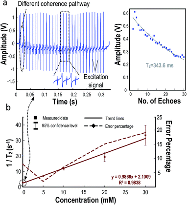
![[thick line, graph caption]](https://www.rsc.org/images/entities/char_e117.gif) ). In addition, the error percentages (defined as half of 95% confidence level/true value) are marked on the graph with dot lines where the values were displayed on the right axis
). In addition, the error percentages (defined as half of 95% confidence level/true value) are marked on the graph with dot lines where the values were displayed on the right axis 