MALDI mechanisms: wavelength and matrix dependence of the coupled photophysical and chemical dynamics model†
Richard
Knochenmuss
Tofwerk, Thun, Switzerland. E-mail: rknochenmuss@gmx.net
First published on 10th October 2013
Abstract
The ultraviolet wavelength and fluence dependence of MALDI ion yields using several matrices has recently been reported (Soltwisch et al., Anal. Chem., 2012, 84, 6567). These extensive data provide a test of the coupled photophysical and chemical dynamics (CPCD) model, and are used to extend the model to new matrices. The experimental phenomena are generally well reproduced by the model, particularly when transient photochemical products or exciplexes are included. While the CPCD is consistent with the data, thermal models appear to be largely incompatible with it.
Introduction
A recent study by Soltwisch et al.1 systematically examined two important factors in MALDI: the effect of laser wavelength and fluence. While it has been known for sometime that the wavelength has a significant effect, and must be more or less matched to the matrix optical absorption spectrum,2–8 there have been few detailed investigations, and none over such wide parameter ranges. The Soltwisch work covers not only the widely used matrices DHB (2,5-dihydroxybenzoic acid) and CHCA (alpha-cyano-4-hydroxycinnamic acid) but also some recently developed halogenated CHCA derivatives, including alpha-cyano-4-chlorocinnamic acid (ClCCA).9 These are interesting since they have blue-shifted absorption profiles and lower proton affinities. This allows some separation of primary ionization effects (absorption spectrum) and secondary reactions (matrix-analyte proton transfer).For five peptides analyzed in positive ion mode they found that the total ion production broadly followed the solid state matrix absorption spectrum, across the lowest electronic absorption band. Analyte signals were divided into two complementary subgroups: molecular ions and fragment ions. The molecular ions were strongest at longer wavelengths, then gave way to the fragments as photon energies increased. As observed at the few commonly used wavelengths (337, 355 nm), there were significant differences in fragment yields between the matrices. Even when analyte and fragments are added together, significant variation in yield with both fluence and wavelength was found. Most remarkably, analyte signals decreased at high fluence in some wavelength regions, for both CHCA and ClCCA. This has been confirmed in more recent work.10
This extensive dataset is not only empirically useful, but also provides an important reference point for evaluating and improving mechanistic understanding of MALDI. Here the data are compared in detail to the coupled photophysical and chemical dynamics (CPCD) model of ultraviolet MALDI.11–17 First developed for DHB matrix only, then extended to analytes, and to include both ion polarities, it remains the only quantitative model demonstrated to be consistent with a wide variety of MALDI phenomena. The CPCD name has been introduced only recently17 to minimize confusion due to the lack of a clear way to describe it.
Another widely discussed model is known as “Lucky Survivors” (LS).18,19 Ions in solution are presumed to be incorporated intact into the solid sample (as opposed to pairing with counterions), and released during ablation. LS make no quantitative predictions, and so relies on qualitative consistency with selected phenomena. Recently, “unification” of LS and “gas phase” models has been claimed.20 This model, and preformed ion models in general, will be examined in later work.
All MALDI models include thermal effects in the form of desorption or ablation. Thermal ionization models of MALDI go back at least to Allwood and Dyer,21,22 with variants such as the polar fluid model.8,23 Although thermodynamic constraints seem daunting,24 there has been a recent resurgence of interest in such models. The Kim group has made a series of observations which led them to suggest that MALDI ion formation is purely thermal, though an exact mechanism has not yet been specified.25–29 A similar conclusion was reached by Liang et al.30 Another ionization model has been proposed recently by the Lee group.31 They called it thermal, but the central mechanism proposed is a pooling reaction of two excited matrix molecules. Their model is therefore a restatement of one part of the CPCD.
Together with the time resolved data of the Tuszynski group on the excitonic and transient photochemistry properties of CHCA,32,33 the Soltwisch data are here used to extend the CPCD to CHCA and ClCCA matrices. The data also allow critical evaluation of the model for the DHB matrix, and some discussion of possible thermal models.
Methods and parameters
The coupled photophysical and chemical dynamics (CPCD) model has been described in ref. 11–13. It is sometimes erroneously referred to as a “gas phase” model. It includes the full MALDI event, from the solid state to collision-free gas. It is a two-step model, and has also been known by that name. The current name has recently been introduced17 to be more descriptive and to reduce confusion. The primary ionization process involves pooling reactions of matrix electronic excitations, generating matrix ions. These ions undergo secondary charge transfer reactions with analyte molecules in the expanding ablation plume. Expansion modulates bimolecular reactions like charge transfer and recombination. Elements of the CPCD are presented in the ESI.† Parameters used in this work are shown in Table 1. The total analyte![[thin space (1/6-em)]](https://www.rsc.org/images/entities/char_2009.gif) :matrix mole ratio used in 1 was 2.5 × 10⁻³. In the calculations presented, a single analyte was assumed, at a mole ratio of 2.0 × 10⁻³.
:matrix mole ratio used in 1 was 2.5 × 10⁻³. In the calculations presented, a single analyte was assumed, at a mole ratio of 2.0 × 10⁻³.
| CHCA monomer | CHCA dimer | CLCA monomer | CLCA dimer | DHB monomer | DHB excimer | |
|---|---|---|---|---|---|---|
| S1 electronic origin, nm | 375 | 400 | 341 | 420 | 357 | 400 |
| Ionization potential, eV | 8.50 | 9.12 | 8.05 | |||
| Free molecule S1 lifetime, ns | 25 | 20 | 30 | |||
| Solid state lifetime, ns | 1.8 | 1.0 | 0.6 | |||
| Peak absorption cross section, cm2 | 7.9 × 10⁻¹⁷ | 3.9 × 10⁻¹⁷ | 6.9 × 10⁻¹⁷ | 2.4 × 10⁻¹⁷ | 9.9 × 10⁻¹⁸ | 8.8 × 10⁻¹⁸ |
| Sn to S1 internal conversion, s−1 | 1.5 × 10¹¹ | 1.5 × 10¹¹ | 7.5 × 10¹⁰ | |||
| S1 + S1 to Sn + S0 pooling, s−1 | 1.0 × 10¹⁰ | 4.6 × 10¹⁰ | 7.0 × 10⁹ | |||
| S1 + Sn to ion pair + S0 pooling, s−1 | 2.0 × 10⁹ | 4.3 × 10⁹ | 1.0 × 10⁹ | |||
| Recombination, s−1 | 1.0 × 10¹¹ | 1.0 × 10¹¹ | 1.0 × 10¹¹ | |||
| C p/Cv | 1.023 | 1.035 | 1.050 | |||
| Ablation temperature, K | 460 | 460 | 450 | |||
| Charge transfer lambda, unitless | 30 | 30 | 15 |
Results and discussion
Wavelength dependence with no other change of parameters
The CPCD predicts a wavelength effect even if no other parameters vary. The form depends on fluence, analyte concentration and charge transfer energetics. Example top layer and depth-integrated results are shown in Fig. 1. These are two important limits. As seen in molecular dynamics simulations14,15 ions are ejected with a wide range of velocities, ions are in collision dominated regimes for varying lengths of time, and those initially in clusters or aggregates may not become free for some time and distance. These factors are a major challenge for any ion optical system. Few, if any, are capable of collecting all MALDI ions. Even if they did, the range of velocities and starting points would lead to low quality spectra. Instead, instruments are pragmatically tuned to collect the most abundant ions which make the fewest collisions – those from the upper sample layers. These are released first and with the highest speed, making them the easiest to collect and analyze.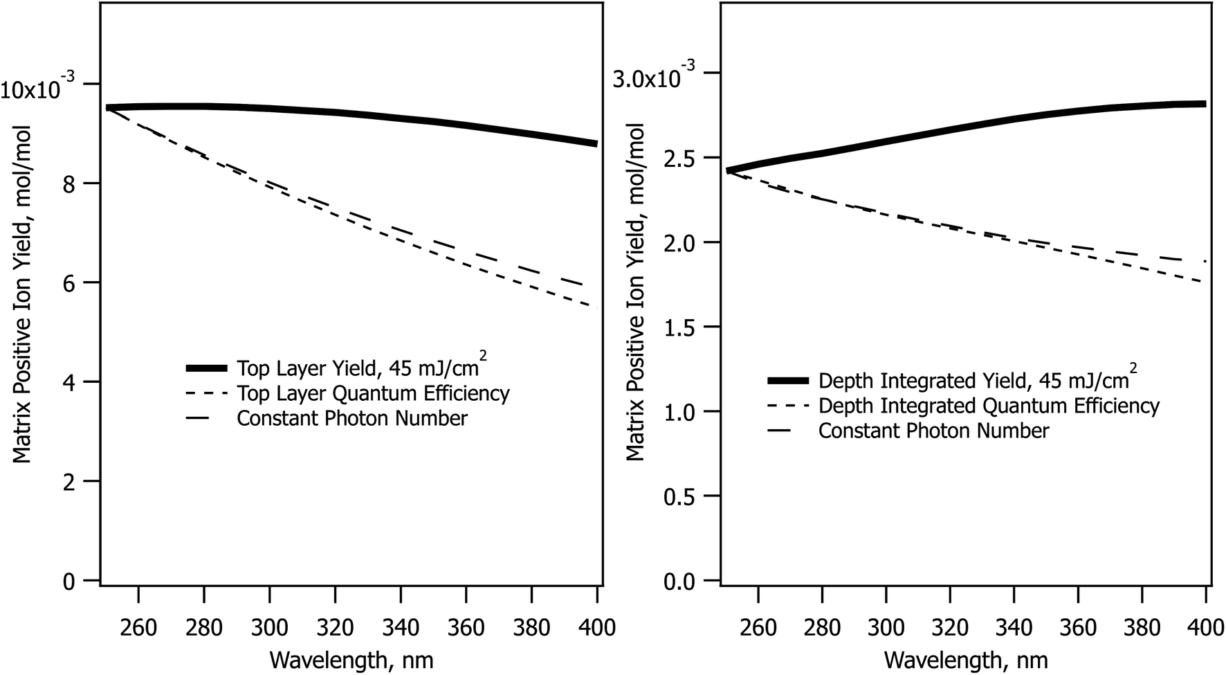 | ||
| Fig. 1 Effect of wavelength in the CPCD model, holding all other parameters constant, for the DHB matrix. The matrix top layer positive ion yield is in the left panel, depth integrated yield in the right. The quantum efficiency traces are the solid traces scaled by the relative number of photons deposited, referenced to the value at 250 nm. The constant photon number traces are the result of CPCD calculations with the fluence scaled to deliver the same number of photons as at 250 nm and 45 mJ cm−2. | ||
MALDI is generally considered to be more fluence than irradiance-dependent,34–37 making the sloping curves of Fig. 1 somewhat surprising. At a fixed sample absorbance, the fluence determines the energy deposited in the sample per unit volume. The large majority of this energy is rapidly converted to heat because solid matrix materials have low fluorescence quantum efficiency. This is wavelength independent as shown in Fig. 1, but the CPCD also includes internal conversion of excess energy above the S1 origin. This wavelength-dependent effect leads to greater heating at shorter wavelengths. Top layer vaporization and plume expansion are then faster, resulting in lower recombination losses. This is why the top layer yield slopes downward at longer wavelength.
The depth integrated yield slopes in the opposite direction. In this case, it is not losses but ion production that determines the shape of the curve. Recombination losses depend on the plume temperature and expansion rate, but depth integration sums the results of hot and cold plume layers, smearing out this effect. Ion production, on the other hand, is equally wavelength dependent at all fluences. Fewer ions are generated at shorter wavelengths because ion formation in the CPCD is a function of the number of deposited photons, not deposited energy. The electronic excited states leading to ions are populated in a quantized manner by photoexcitation. The short wavelength net ion yield is therefore lower in the integrated case because fewer ions are created for the same ablated volume.
The photon number effect yield is shown in Fig. 1 by the long dashed traces. Rather than keeping the fluence constant, the photon number was held at the value needed to deposit 45 mJ cm−2. This can be compared to the quantum efficiency curve, which is the solid line divided by the photon number. The two dashed curves are almost identical.
Absorption cross-section dependence with no other change of parameters
The CPCD predicts that top layer matrix primary ion production rises with absorption cross-section, as seen in Fig. 2. The detailed shape of the curve depends on the analyte concentration and charge transfer energetics, as well as photon number (fluence). The analyte yield has a less monotonic dependence, in some cases rolling over. Once again, it is the rate of plume expansion which plays a key role here. Instead of recombination, another bimolecular reaction is at work here, charge transfer from matrix to neutral analyte. If the plume expands faster due to greater heating, there is less time for these secondary reactions, and the analyte yield drops. Less exoergic reactions are also slower, making them more sensitive to this effect.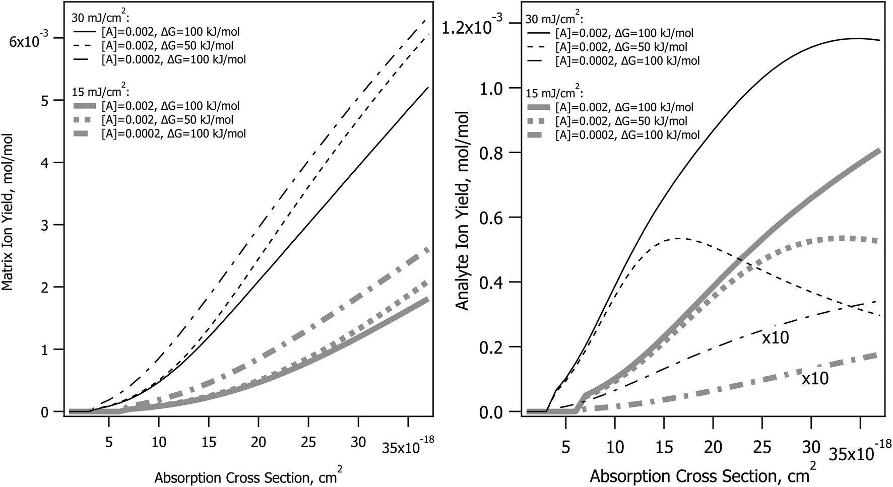 | ||
| Fig. 2 Effect of absorption cross-section in the CPCD model, holding all other parameters constant, for the DHB matrix. The matrix top layer positive ion yield is shown in the left panel, for different fluences, analyte concentrations and secondary charge transfer reaction energetics. The corresponding analyte yields are in the right panel. | ||
Incommensurate matrix and analyte yield similar to Fig. 2 was an important observation in ref. 1 for CHCA and ClCCA matrices. The effect arises naturally in the CPCD, as a result of secondary reactions and plume expansion.
CHCA matrix
Fig. 3 shows the interpolated and smoothed data of ref. 1 (center panels) and the corresponding CPCD results for the CHCA matrix. See the ESI† for discussion of the data treatment. The experimental data exhibit some interesting and unexpected features. The matrix (top center) has a quite narrow peak at about 320 nm, which is both narrower and 20 nm below the peak of the solid state absorption spectrum (gray trace in left panels). It corresponds more to the solution phase spectrum (solid gray trace in right panel). The blue edge may show some structure, but this is uncertain, the data are incomplete. The red side drops less slowly than does the blue, especially at lower fluences.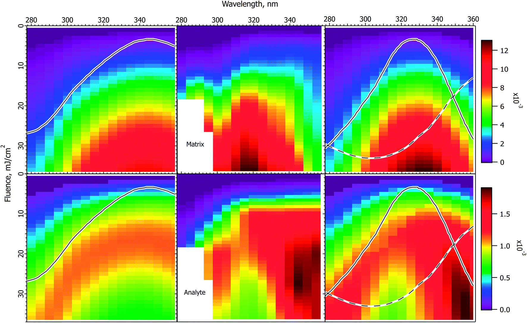 | ||
| Fig. 3 Fluence vs. wavelength plots for CHCA matrix. The experimental data of ref. 1 are in the middle column (analyte molecular ions and fragments are summed, see the ESI†). Matrix plots are in the top row, total analyte on the bottom. The ion yield color scales (mol mol−1) apply to the calculated results in their respective rows, not to the experimental data. The normalized solid state spectrum of ref. 1 is shown in the left panels. The normalized solution spectrum is shown as a solid line in the right panels. The estimated dimer spectrum is shown as a dashed line. In the CPCD calculations the analyte mole fraction was 0.002 mol mol−1. The positive charge transfer reaction free energy was ΔG = −100 kJ mol−1. The left panels are the top layer CPCD results using the solid state spectrum. The right panels are the composite monomer + dimer CPCD results, summed in 1:0.7 ratio. The composite calculation reproduces all key features of the experimental data. See the text for further details. | ||
The total peptide signal, molecular plus fragment ions, is shown in the bottom center panel. These are not considered separately as in ref. 1, because the CPCD does not currently include any fragmentation pathways. Starting around 300 nm and extending to lower wavelength, aromatic amino acid sidechains begin to directly absorb the laser light, but not all the peptides tested had such sidechains. Since all nevertheless fragmented similarly, photochemical pathways were ruled out by Soltwisch et al. This would suggest that fragmentation must be due to thermal unimolecular decay, but the fragment yield correlates poorly with the calculated plume temperatures, as shown in the ESI.†
Here, and unless otherwise noted, the CPCD results are for the top sample layer, and are not integrated over the ablated depth. This follows Soltwisch et al., who concluded that their data largely represent top layers, and are expected to be typical for most instruments, as noted above. This is also consistent with the plume dynamics results of Liang et al., who found most analyte ablated early,38 and therefore from top layers. Depth integration was found to “wash out” structure of the kinds noted above in the data, while the top layer results gave good agreement. Example depth-integrated plots are shown in the ESI.†
A dramatic and quite surprising feature of the analyte data is the deep dip at high fluence, near 320 nm, the location of the maximum matrix yield. This is reminiscent of the drop in analyte signal at high cross-section in Fig. 2. Another striking feature is the high intensity at the right edge of the plot. This is roughly at the position of the solid state absorption peak, but is not nearly so broad. The left side drops smoothly toward short wavelength, while the right side remains quite high to the edge of the data. The large triangular region of high intensity at short wavelength is connected to the ridge defining the high fluence dip, the ridge decays to the left, with a saddle. This fading at short wavelength is reminiscent of the gradual changes in Fig. 1.
The first effort to reproduce the CHCA data used the solid state absorption spectrum, as shown in the left panels for matrix (upper) and analyte (lower). The data are discussed in ref. 1 in terms of this spectrum, but it is immediately evident from the CPCD results that it gives only moderate agreement with the data. The matrix peak is too broad and far to the red. The analyte plot has a pronounced dip at high fluence, which is very encouraging, but the surrounding ridge is much too broad and too symmetric.
In the absence of further information, this result could be considered a moderate success, since the general shapes and the analyte dip are all somewhat reproduced. However, the matrix peak and analyte dip both seem to correspond to the solution spectrum, suggesting processes localized on a single matrix molecule. This fits with the conclusion of the Tuszynski group that CHCA engages in excitonic interactions, undergoes dimerization on a timescale of about 20 ps, and that the dimer is long lived, emitting a large part of the long wavelength fluorescence.32,33 This suggests the hypothesis that the MALDI response is a superposition of at least two processes. It is possible that the dimer is one of the active species, or it may be that some as yet undefined exciplex is more important. Other photochemical or photothermal processes in CHCA and DHB are known, in particular decarboxylation.39–41 Such species are also potential candidates for a second ionization pathway.
The simplest approach to testing the dual population hypothesis is to assume that the solid state spectrum can be decomposed into two components, which are here called monomer and dimer. As noted above, either or both descriptions may be imprecise. In any case, the solution spectrum was subtracted from the solid state spectrum to give an approximation of a possible dimer spectrum. This is shown as dashed traces in the right panels of Fig. 3.
The right 2-D plots are summed results of monomer and dimer, using the respective absorption spectra. The best shape of the 2D features was found using a peak dimer cross-section less than that of the monomer. In addition, the relative contributions of the two populations must be specified. As Hoyer and Tuszynski showed,32,33 the populations will change throughout the MALDI laser pulse, these dynamics are not modeled here. Instead an empirical ratio of 1:0.7 monomer:dimer was found to give a reasonable match to the intensity patterns in the plots. While a 1:1 ratio would reflect the spectrum subtraction process, a moderate deviation from this proportion seems to be a reasonable correction for the poorly characterized pathways and relative ionization efficiencies.
As is evident in the right panels of Fig. 3, all of the unusual features of the data are reproduced using the dual population hypothesis: the analyte dip, the location of the maxima, the width of the maxima, the ridge around the dip fading to the left, even the saddle in the ridge. Given that the experimental plots are based on quite limited data, with significant internal variation, these results are considered satisfactory, more so than using the solid state spectrum.
MALDI ion yields have mostly been found to be in the 10−4 to 10−3 mol mol−1 range,42–46 although there have been recent reports of 10−4 to 10−9.27,47 The calculated yields in Fig. 3 are in this more commonly cited range, for which the model was originally parameterized. The maximum values reach just over 10−2, but the highest fluences are, of course, beyond those typically used. A much lower ionization yield is possible in the model by reducing the rate of the second (S1 + Sn) pooling step, or increasing the Sn nonradiative decay rate. Since the wavelength and fluence dependencies are mostly dependent on processes prior to the these steps, the shapes of the results as in Fig. 3 are not found to depend strongly on them. Finally, it should also be recalled that analyte and matrix relative yields depend on the analyte concentration in the sample, which can lead to significant suppression effects.48,49
ClCCA matrix
Fig. 4 shows experimental and calculated wavelength vs. fluence plots for the ClCCA matrix. The experimental data exhibit similar characteristics to CHCA, but shifted to the blue. In particular, the matrix pattern is narrower than the solid state absorption spectrum, the analyte exhibits a dip at high fluence, which corresponds to the solution spectrum, and is stronger on the red side.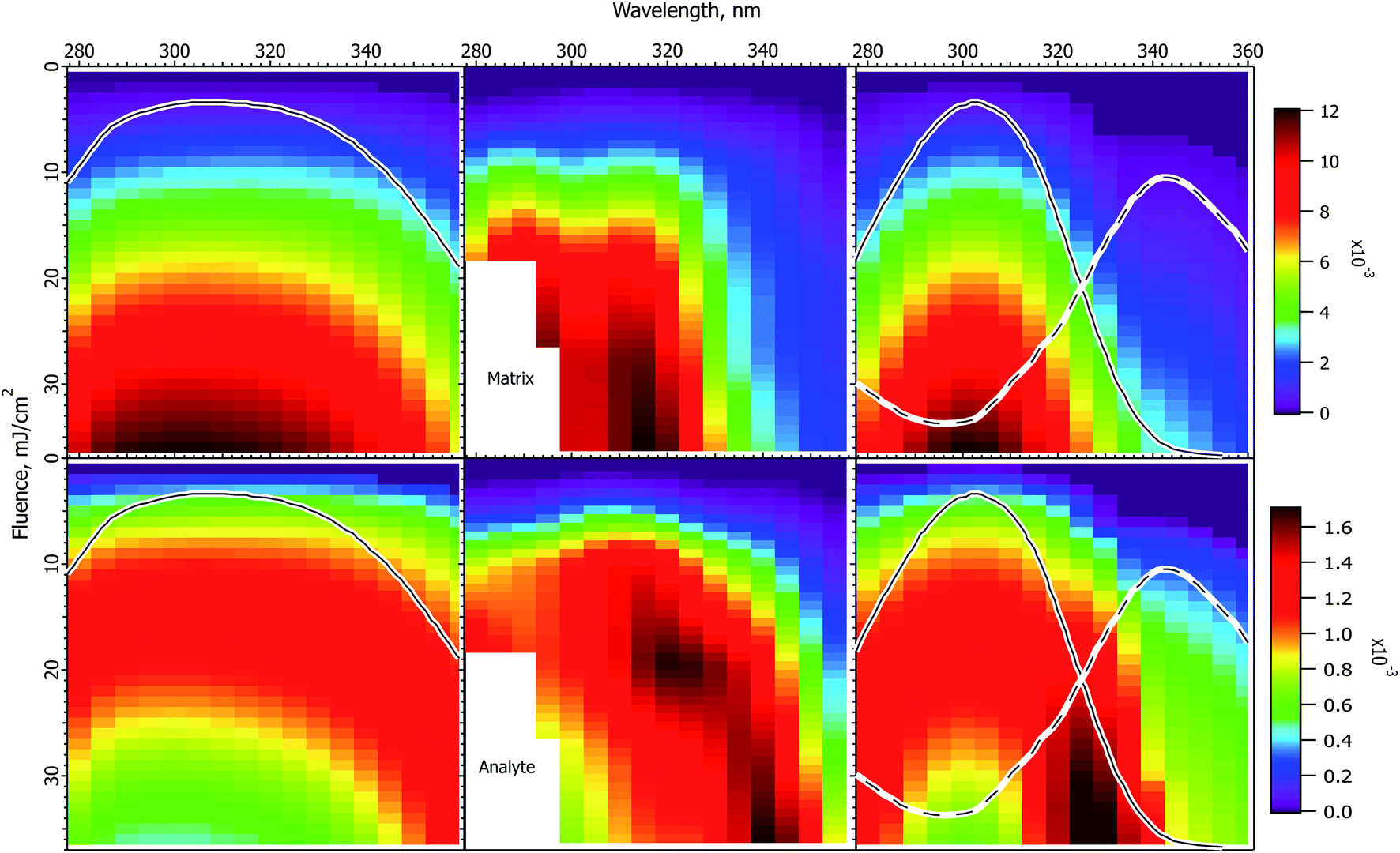 | ||
| Fig. 4 Fluence vs. wavelength plots for the ClCCA matrix. The experimental data of ref. 1 are in the middle column (analyte molecular ions and fragments are summed, see the ESI†). Matrix plots are in the top row, analyte on the bottom. The ion yield color scales (mol mol−1) apply to the calculated results in their respective rows, not to the experimental data. The normalized solid state spectrum of ref. 1 is shown in the left panels. The normalized solution spectrum is shown as a solid line in the right panels. The estimated dimer spectrum is shown as a dotted line. In the CPCD calculations the analyte mole fraction was 0.002 mol mol−1. The positive charge transfer reaction free energy was ΔG = −125 kJ mol−1. The left panels are the CPCD results using the solid state spectrum. The right panels are the composite monomer + dimer CPCD results, summed in 1:0.8 ratio. The composite calculation reproduces all key features of the experimental data. See the text for further details. | ||
The CPCD calculation using the solid state spectrum is in the left panels, with the spectrum. As for CHCA, agreement with experiment is moderate. The matrix signal is too broad, though the peak is in the right wavelength range. The analyte exhibits a high fluence dip region, but this is also too broad. The ridge of the highest intensity is too strong on the blue side.
Although no data regarding photodimerization exist for this matrix, the chemical similarity and the similarity of the data to CHCA are strong, suggesting that the hypothesis of monomer and dimer subpopulations is also applicable. Once again the solution spectrum was subtracted from the solid state spectrum to estimate the dimer spectrum. This is shown as a dashed line in the right panels. As for CHCA, the best result was obtained with a lower peak cross-section than the monomer. The two components were then summed in a 1:0.8 ratio.
The result in the right panels of Fig. 4 is distinctly better than using the solid state spectrum. The matrix peak has appropriate width, although it is not as flat as the experimental data. The analyte dip region is well reproduced, along with the general shape and intensity pattern of the ridge. While not all details are reproduced as well as for CHCA, the key features are all present. The ion yields for both matrix and analyte are similar to those of CHCA, as found experimentally.
DHB matrix
The experimental and calculated results for DHB matrix are shown in Fig. 5. Because of the lower absorption cross-section compared to the cinnamic acid derivatives, the data do not extend as far above threshold, and have less structure. Nevertheless, some similarities to the cinnamic acid matrices are apparent. Both matrix and analyte are more peaked than the solid state spectrum, and are asymmetric in form. The positions of the maxima correspond best to the solution spectrum, although they do not match exactly.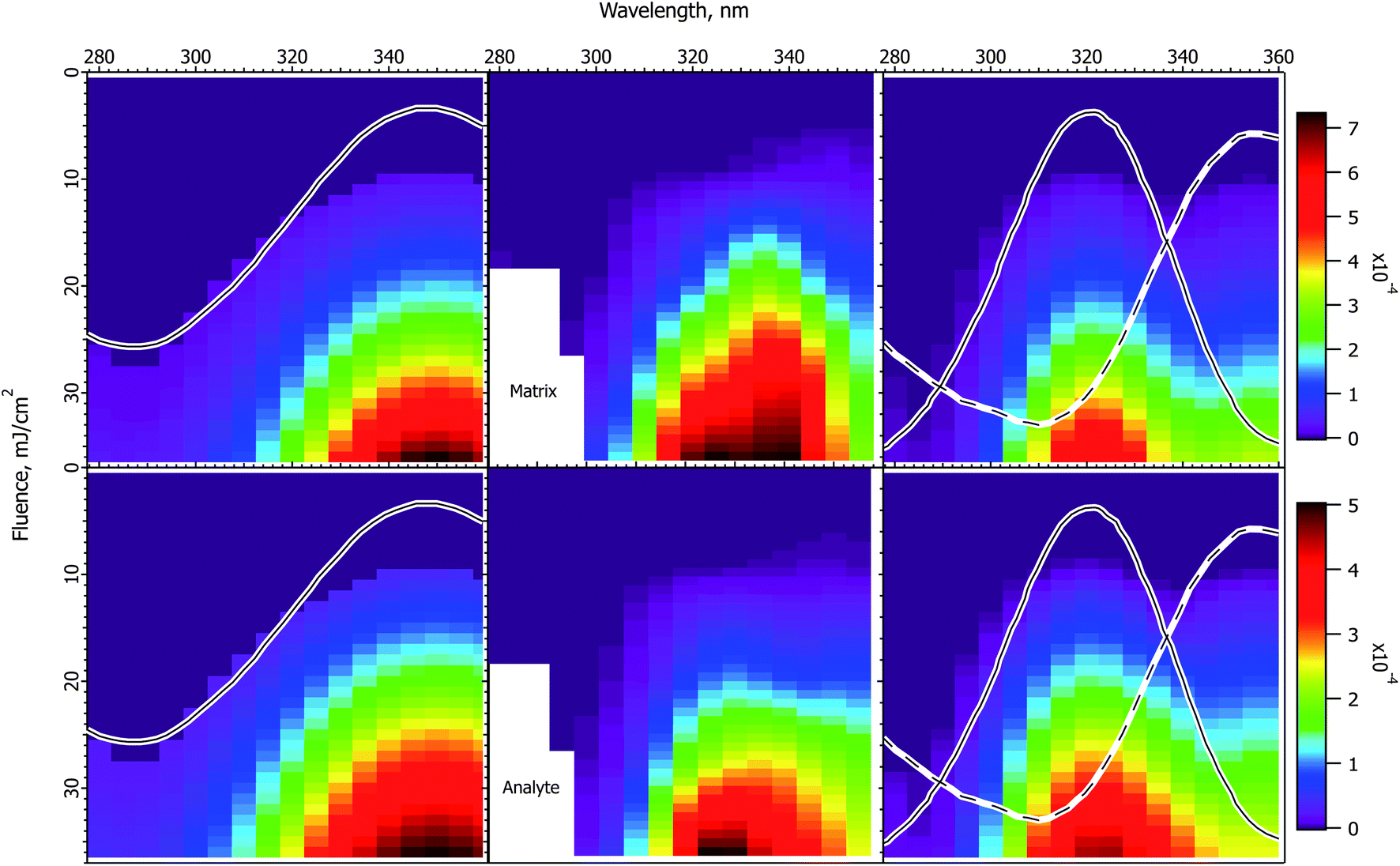 | ||
| Fig. 5 Fluence vs. wavelength plots for the DHB matrix. The experimental data of ref. 1 are in the middle column (analyte molecular ions and fragments are summed, see the ESI†). Matrix plots are in the top row, analyte on the bottom. The ion yield color scales (mol mol−1) apply to the calculated results in their respective rows, not to the experimental data. The normalized solid state spectrum of ref. 1 is shown in the left panels. The normalized solution spectrum is shown as a solid line in the right panels. The estimated exciplex spectrum is shown as a dotted line. In the CPCD calculations the analyte mole fraction was 0.002 mol mol−1. The positive charge transfer reaction free energy was ΔG = −100 kJ mol−1. The left panels are the CPCD results using the solid state spectrum. The right panels are the composite monomer + exciplex CPCD results, summed in 1:0.55 ratio. See the text for further details. | ||
The CPCD result using the solid state spectrum agrees moderately well with the data, but is too broad on the blue side, and the peak is too far to the red. This leads to the surprising conclusion that it would be reasonable to postulate a two-component system also for this matrix. Since there is no evidence for, and the molecule is not capable of, the same kind of dimerization proposed for the cinnamic acid derivatives (cycloaddition of the double bonds in the aliphatic sidechain), the two hypothesized species are denoted as monomer and excimer.
Following the now familiar procedure, the composite monomer + excimer CPCD calculation is shown in the right panels. The mixing ratio was 1:0.55 monomer:excimer. The match to the experimental data is again noticeably improved. The maxima are in the appropriate locations, and the asymmetric “wing” to the red side is present. The signals drop more quickly toward short wavelength, as they should. The ion yields are about an order of magnitude lower than with CHCA or ClCCA, corresponding well with the results of Soltwisch et al.
Charge transfer energetics
In addition to the differences in the absorption spectrum, the matrices compared here are of interest also because their calculated proton affinities differ. DHB and CHCA have a similar proton affinity, while that of ClCCA is calculated to be about 25 kJ mol−1 less. This increases the free energy of secondary charge transfer with analyte by the same amount, and was taken into account above.If secondary reactions are at least moderately favorable, they can be fast enough (in the forward direction) that the final MALDI spectrum is relatively insensitive to changes in reaction exoergicity at typical fluences. This was shown most dramatically for positive/negative ion ratios,13 which only become significantly ΔG-dependent at low exoergicities. However, over the very large range of fluences considered here, the rate of plume expansion varies considerably, and strongly modulates the rate of secondary reactions. This makes the fluence–wavelength plots more sensitive to the reaction free energies in at least some regions.
This is illustrated in Fig. S6, ESI† for CHCA at a positive reaction free energy of ΔG = −50 kJ mol−1. This figure should be compared with Fig. 3 (ΔG = −100 kJ mol−1). The matrix distribution does not change significantly, but that of the analyte does, due to much different secondary rates. At the same time, in the low fluence region, near the threshold, there is not much to differentiate the different ΔG values. This once again illustrates the value of this extensive dataset.
Analyte relative ion yields
Up to this point, absolute ion yields have not been extensively discussed due to the lack of comparable data. Relative ion yields are, however, more accessible. Soltwisch et al. reported analyte yields as a fraction of the total ion current. The maximum values for each matrix were quite high, ranging from slightly below 40% (CHCA) to 55% (DHB). Once again the cinnamic acid derivatives exhibited distinctly different patterns than DHB. Relative analyte yields in CHCA and ClCCA were highest at lower fluences, while they peaked at higher fluence in DHB.Relative yield measurements are useful since they provide a means to constrain the secondary reaction rate parameters of the model. This is particularly strongly modulated by the lambda parameter in the nonlinear free energy equation relating reaction free energy to the activation energy. See ref. 12 for more discussion of this aspect of the CPCD. For DHB the original value of 15 was retained here, which is at the low end of the range originally proposed for proton transfer reactions.50,51 With this value, the relative analyte yields for CHCA and ClCCA were too high. Raising lambda to 30 gives better agreement with the data.
Relative analyte ion yields are shown in Fig. S7, ESI.† The CPCD peak values are in good agreement with the data, for all three matrices. The CHCA and ClCCA plots decrease more rapidly at higher fluence than measured, but the maxima at relatively low fluences are correct. The calculated DHB plots peak earlier than the data, but remain uniformly high at higher fluence, as measured. It should be noted that the experimental plots are the ratios of two sparse arrays which have been interpolated. The uncertainty in the result is correspondingly higher than in the other figures. The limits of both the data and the model are probably reached here.
Sample heating and thermal ionization
The maximum fluences considered here are very high, well above normal values. Though not practical, they are useful for evaluating models. These include not only the CPCD, but also purely thermal ones.One of the oldest thermal MALDI models was proposed by Allwood and Dyer.21,22 After corrections, it was found that it contributes very little at normal MALDI fluences. In the polar fluid model,8,23 the hot, dense matrix is presumed to allow charge separation by solvation of ions. However, dielectric constants of matrix-like materials are low even at room temperature, and at MALDI temperatures and pressures they approach 1 for all substances, even water.52 Calculated ion yields under such conditions are below all experimental estimates. The Kim group has recently proposed in a series of papers that MALDI spectra are determined by a characteristic plume temperature, and that all ions are created by thermal processes, though the exact mechanism was not specified.25–28 A key assumption of the model is that the ion distribution is determined by the highest temperatures reached. A key unstated assumption is that this distribution is then rapidly frozen, and does not change significantly as the plume expands and cools.
What thermal ionization models have in common is that the ion yield should be highest at the highest temperatures. If both matrix and analyte ions are separately formed thermally, each should follow the temperature distribution. If only matrix ions are formed directly, then the matrix should follow the temperature, while analyte will be modulated by the plume, analogous to the CPCD. However, if few matrix ions are created, secondary reactions and plume modulation are moot.
The peak temperatures achieved in a MALDI experiment are found in the top layer, which experiences the highest volumetric energy deposition. Fig. 6 shows the top layer peak temperatures calculated using the CPCD and the solid state absorption spectra, for all three matrices. The data for matrix and analyte ion production are compared in the adjacent rows.
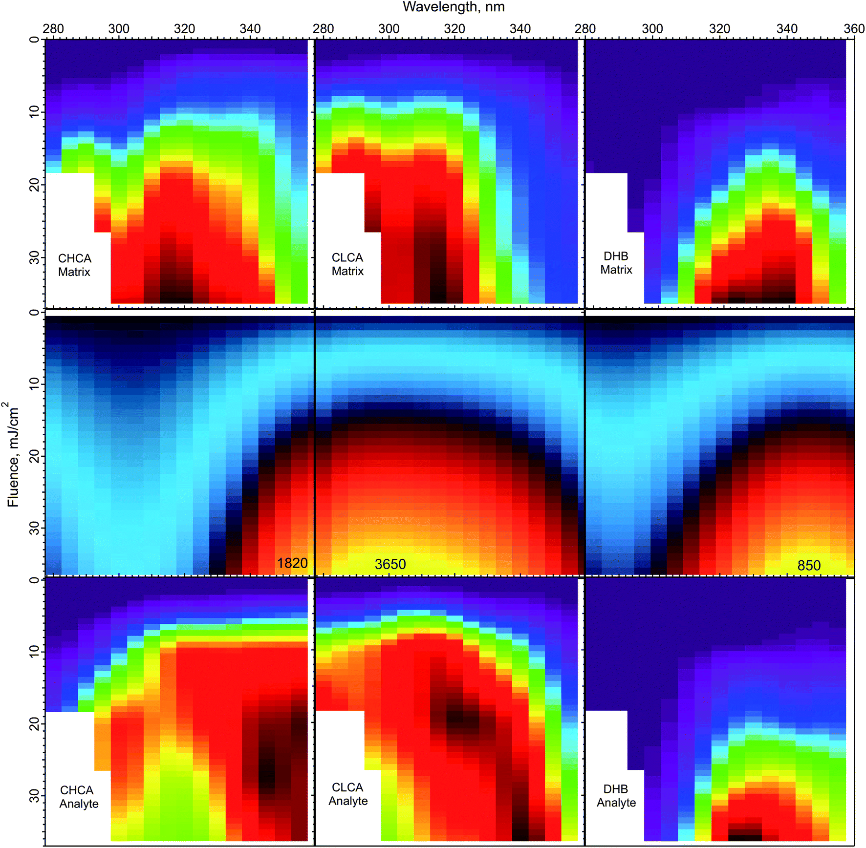 | ||
| Fig. 6 Peak top layer temperatures calculated using the CPCD and the solid state absorption spectra, for the matrices CHCA, ClCCA and DHB (middle row). The top and bottom rows are the respective matrix and analyte yields from ref. 1. The highest temperatures in the middle panels are (K): CHCA: 3265, ClCCA: 3650, and DHB: 850. On the basis of these results, the DHB temperature distribution could be compatible with a thermal ionization model, but such a model appears inconsistent with the data for ClCCA and CHCA. | ||
The temperature plot for DHB has a peak somewhat too far to the red, compared to both matrix and analyte ion distributions. However, the discrepancy may be within the uncertainty of the data, so a thermal model for DHB cannot be ruled out from this comparison alone.
ClCCA and CHCA are another story. The matrix yield of ClCCA drops abruptly at wavelengths longer than 330 nm, but the temperature pattern is much smoother. The peak of the temperature distribution coincides not with the maximum analyte ion yield, but with the dip. The region of high analyte yield at 15–20 mJ cm−2 and 320–340 nm is relatively cold, while regions of similar temperature at other wavelengths exhibit lower yield. The discrepancies for CHCA are also significant. The temperature peak does not correspond to a peak in either matrix or analyte ion production.
The correspondence of temperature with yields can be summarized by the correlation coefficients of the data in Fig. 6. For DHB, these are matrix: 0.89, analyte: 0.89. For CHCA, matrix: 0.85, analyte: 0.76. For ClCCA, matrix: 0.81, analyte: 0.73. These results add to the arguments against a thermal model for CHCA and ClCCA.24
Conclusions
The coupled chemical and physical dynamics model of MALDI has been compared with the wavelength vs. fluence data of Soltwisch et al.1 The dataset provided a test of the existing DHB model and allowed extension to the matrices CHCA and ClCCA. These matrices allow comparison of the effect of absorption cross-section, wavelength of maximum absorption and secondary reaction energetics.Using the matrix solid state absorption spectra as measured by Soltwisch et al., some details of the data are not reproduced, although the major trends are correct. Inclusion of a second absorbing species, in addition to the matrix monomer, of CHCA and ClCCA, along the general lines of the transient photodimer proposed by Hoyer and Tuszynski for CHCA,32,33 was found to significantly improve agreement with the data. The identities and dynamics of the species responsible for the hypothesized second channel are currently unknown, though the dimer of Hoyer and Tuszynski is obviously a candidate. The empirical success of decomposing the solid state absorption spectra into two components is considered sufficient justification for further consideration of this hypothesis.
The two proposed active species were modeled separately, and the results summed in empirically determined ratios. Surprisingly, since DHB cannot undergo the same dimerization reaction as the cinnamic acids, inclusion of a DHB excimer also improved the results, though the excimer contribution is smaller. With the second channel, agreement of the model results with the data is considered to be within the limitations of the data.
The present results indicate that the CPCD parameters for the DHB matrix monomer need no modification. Compared to DHB, CHCA and ClCCA are characterized by somewhat faster pooling processes and slightly slower secondary reaction kinetics. The factor having the largest effect is the absorption cross-section. The cinnamic acids absorb the laser much more strongly than DHB, which leads to different plume characteristics, with associated kinetic limitations of secondary plume reactions. As a result, the analyte yield drops at high fluences, even as matrix ion production rises. This kinetic limitation is not consistent with models assuming reaction equilibrium in the plume.29
Examination of the wavelength dependence of the CPCD, with all other factors held constant, shows that it is not a fluence-dependent model, but rather scales with photon number. The results suggest that this factor is responsible for much of the red/blue asymmetry in the data. At fixed wavelength there is no difference between the two, but any comparison involving more than one wavelength should take this into account.
Correspondence of the calculated temperature profiles with matrix and analyte ion production for CHCA and ClCCA matrices was found to be unsatisfactory. Thermal mechanisms of MALDI ion production therefore do not appear to be compatible with the data.
The extensive data provided by Soltwisch et al. are a significant challenge, since a wide variety of conditions must be modeled correctly, even those well outside of normal MALDI practice. The agreement with the data suggests that the CPCD may successfully approximate and integrate the major phenomena in MALDI, both physical and chemical. Matrix excitation, excitonic processes, ion–molecule reactions, ablation and expansion are all necessary components of the model, and shape the final result through their interactions.
Acknowledgements
The author thanks Klaus Dreisewerd and Jens Soltwisch for making their original data available and for helpful discussions. He also thanks Kevin Owens for numerous suggestions and discussion.References
- J. Soltwisch, T. W. Jaskolla, F. Hillenkamp, M. Karas and K. Dreisewerd, Anal. Chem., 2012, 84, 6567–6576 CrossRef CAS PubMed.
- J. Zhang and G. R. Kinsel, Langmuir, 2002, 18, 4444–4448 CrossRef CAS.
- V. Horneffer, K. Dreisewerd, H.-C. Lüdemann, F. Hillenkamp, M. Laege and K. Strupat, Int. J. Mass Spectrom., 1999, 185–187, 859–881 Search PubMed.
- M. Karas, D. Bachmann and F. Hillenkamp, Anal. Chem., 1985, 57, 2935–2939 CrossRef CAS.
- R. C. Beavis, T. Chaudary and B. T. Chait, Org. Mass Spectrom., 1992, 27, 156–158 CrossRef CAS.
- J. R. Haulenbeek, PhD, Dept of Chemistry, Drexel University, Philadelphia, 2012.
- M. Wiegelmann, J. Soltwisch, T. W. Jaskolla and K. Dreisewerd, Anal. Bioanal. Chem., 2013, 405, 6925–6932 CrossRef CAS PubMed.
- X. Chen, J. A. Carroll and R. C. Beavis, J. Am. Soc. Mass Spectrom., 1998, 9, 885–891 CrossRef CAS.
- T. W. Jaskolla, W. D. Lehmann and M. Karas, Proc. Natl. Acad. Sci. U. S. A., 2008, 105, 12200–12205 CrossRef CAS PubMed.
- J. Soltwisch, T. W. Jaskolla and K. Dreisewerd, J. Am. Soc. Mass Spectrom., 2013, 24, 1477–1488 CrossRef CAS PubMed.
- R. Knochenmuss, J. Mass Spectrom., 2002, 37, 867–877 CrossRef CAS PubMed.
- R. Knochenmuss, Anal. Chem., 2003, 75, 2199 CrossRef CAS.
- R. Knochenmuss, Int. J. Mass Spectrom., 2009, 285, 105–113 CrossRef CAS PubMed.
- R. Knochenmuss and L. V. Zhigilei, J. Phys. Chem. B, 2005, 109, 22947–22957 CrossRef CAS PubMed.
- R. Knochenmuss and L. V. Zhigilei, J. Mass Spectrom., 2010, 45, 333–346 CAS.
- R. Knochenmuss and L. V. Zhigilei, Anal. Bioanal. Chem., 2012, 402, 2511–2519 CrossRef CAS PubMed.
- R. Knochenmuss, J. Mass Spectrom., 2013, 48, 998–1004 CrossRef CAS PubMed.
- M. Karas and R. Krueger, Chem. Rev., 2003, 103, 427–439 CrossRef CAS PubMed.
- M. Karas, M. Glückmann and J. Schäfer, J. Mass Spectrom., 2000, 35, 1–12 CrossRef CAS.
- T. W. Jaskolla and M. Karas, J. Am. Soc. Mass Spectrom., 2011, 22, 976–988 CrossRef CAS PubMed.
- D. A. Allwood, P. E. Dyer and R. W. Dreyfus, Rapid Commun. Mass Spectrom., 1997, 11, 499–503 CrossRef CAS.
- D. A. Allwood, P. E. Dyer, R. W. Dreyfus and I. K. Perera, Appl. Surf. Sci., 1997, 110, 616–620 CrossRef.
- S. Niu, W. Zhang and B. T. Chait, J. Am. Soc. Mass Spectrom., 1998, 9, 1–7 CrossRef CAS.
- R. Knochenmuss, Mass Spectrom., 2013, 2, S0006 CrossRef.
- J. H. Moon, Y. S. Shin, Y. J. Bae and M. S. Kim, J. Am. Soc. Mass Spectrom., 2011, 23, 162–170 CrossRef PubMed.
- J. H. Moon, S. H. Yoon and M. S. Kim, J. Phys. Chem. B, 2009, 113, 2071–2076 CrossRef CAS PubMed.
- Y. J. Bae, Y. S. Shin, J. H. Moon and M. S. Kim, J. Am. Soc. Mass Spectrom., 2012, 23, 1326–1335 CrossRef CAS PubMed.
- Y.-H. Lai, C.-C. Wang, S.-H. Lin, Y. T. Lee and Y.-S. Wang, J. Phys. Chem. B, 2010, 114, 13847–13852 CrossRef CAS PubMed.
- S. H. Ahn, K. M. Park, Y. J. Bae and M. S. Kim, J. Mass Spectrom., 2013, 48, 299–305 CrossRef CAS PubMed.
- C. W. Liang, C. H. Lee, Y.-J. Lin, Y. T. Lee and C. K. Ni, J. Phys. Chem. B, 2013, 117, 5058–5064 CrossRef CAS PubMed.
- Y.-H. Lai, C.-C. Wang, C. W. Chen, B.-H. Liu, S. H. Lin and Y. T. Lee, J. Phys. Chem. B, 2012, 116, 9635–9643 CrossRef CAS PubMed.
- T. Hoyer, PhD thesis, Fakultät für Mathematik und Naturwissenschaften, Carl von Ossietzky Universität Oldenburg, Oldenburg, 2009 Search PubMed.
- T. Hoyer, W. Tuszynski and C. Lienau, Chem. Phys. Lett., 2007, 443, 107–112 CrossRef CAS PubMed.
- K. Riahi, G. Bolbach, A. Brunot, F. Breton, M. Spiro and J.-C. Blais, Rapid Commun. Mass Spectrom., 1994, 8, 242–247 CrossRef CAS.
- K. Dreisewerd, M. Schürenberg, M. Karas and F. Hillenkamp, Int. J. Mass Spectrom. Ion Processes, 1996, 154, 171–178 CrossRef CAS.
- A. Vertes, G. Luo and Y. L. C. Y. I. Marginean, Appl. Phys. A, 2004, 79, 823–825 CrossRef CAS PubMed.
- P. Demirev, A. Westman, C. T. Reimann, P. Håkansson, D. Barofsky, B. U. R. Sundqvist, Y. D. Cheng, W. Seibt and K. Siegbahn, Rapid Commun. Mass Spectrom., 1992, 6, 187–191 CrossRef CAS.
- C. W. Liang, C. H. Lee, Y. T. Lee and C. K. Ni, Chem.–Asian J., 2011, 6, 2986–2991 CrossRef CAS PubMed.
- O. I. Tarzi, H. Nonami and R. Erra-Balsells, J. Mass Spectrom., 2009, 44, 260–277 CrossRef CAS PubMed.
- I. Fournier, J.-C. Tabet and G. Bolbach, Int. J. Mass Spectrom., 2002, 219, 515–523 CrossRef CAS.
- I. Fournier, C. Marinach, J.-C. Tabet and G. Bolbach, J. Am. Soc. Mass Spectrom., 2003, 14, 893–899 CrossRef CAS.
- A. A. Puretzky and D. B. Geohegan, Chem. Phys. Lett., 1997, 286, 425–432 CrossRef.
- K. Dreisewerd, M. Schürenberg, M. Karas and F. Hillenkamp, Int. J. Mass Spectrom. Ion Processes, 1995, 141, 127–148 CrossRef CAS.
- C. Mowry and M. Johnston, Rapid Commun. Mass Spectrom., 1993, 7, 569–575 CrossRef CAS.
- A. P. Quist, T. Huth-Fehre and B. U. R. Sundqvist, Rapid Commun. Mass Spectrom., 1994, 8, 149–154 CrossRef CAS.
- W. Ens, Y. Mao, F. Mayer and K. G. Standing, Rapid Commun. Mass Spectrom., 1991, 5, 117–123 CrossRef CAS PubMed.
- M.-T. Tsai, S. Lee, I.-C. Lu, K. Y. Chu, C.-W. Liang, C. H. Lee, Y. T. Lee and C.-K. Ni, Rapid Commun. Mass Spectrom., 2013, 27, 955–963 CrossRef CAS PubMed.
- R. Knochenmuss, V. Karbach, U. Wiesli, K. Breuker and R. Zenobi, Rapid Commun. Mass Spectrom., 1998, 12, 529–534 CrossRef CAS.
- R. Knochenmuss, F. Dubois, M. J. Dale and R. Zenobi, Rapid Commun. Mass Spectrom., 1996, 10, 871–877 CrossRef CAS.
- N. Agmon, Int. J. Chem. Kinet., 1981, 13, 333–365 CrossRef CAS.
- N. Agmon and R. D. Levine, Isr. J. Chem., 1980, 19, 330–336 CAS.
- M. Uematsu and E. U. Franck, J. Phys. Chem. Ref. Data, 1980, 9, 1291–1306 CrossRef CAS.
Footnote |
| † Electronic supplementary information (ESI) available. See DOI: 10.1039/c3an01446k |
| This journal is © The Royal Society of Chemistry 2014 |