Tunable topological surface and realization of insulating massive Dirac fermion state in Bi2Te2Se with co-substitution
Chengwang
Niu
a,
Ying
Dai
*a,
Meng
Guo
a,
Yandong
Ma
a,
Baibiao
Huang
a and
Myung-Hwan
Whangbo
b
aSchool of Physics, State Key Laboratory of Crystal Materials, Shandong University, Jinan 250100, People's Republic of China. E-mail: daiy60@sina.com
bDepartment of Chemistry, North Carolina State University, Raleigh, North Carolina 27695-8204, USA
First published on 22nd October 2012
Abstract
The ternary topological insulator Bi2Te2Se is exceptional as it has a larger bulk resistivity than previously studied topological insulators. Here we explored the possibility of modifying the topological surface states and achieving the insulating massive Dirac fermion state in Bi2Te2Se on the basis of density functional calculations. Substitution of O for the outmost-layer Te leads to tunable surface states with an ideal Dirac cone. The co-substitution of Cr and O, as well as that of Mn and F, for the surface Bi and Te places the Dirac point inside the bulk band gap and opens a band gap at the Dirac point, hence creating the insulating massive Dirac fermion state. The co-substitution of magnetic and non-magnetic elements is a promising way of tuning the properties of topological insulators.
I. Introduction
A topological insulator (TI) exhibits a novel quantum state of matter characterized by the insulating bulk and topologically protected metallic surface.1–3 The topological surface state (TSS) of a TI is immune to disorder-induced localization so long as the disorder potential does not break the time reversal symmetry (TRS), but this robust metallicity of the TSS is destroyed once the TRS is broken by introducing magnetic impurities,4,5 and the intricate interplay between topological order and ferromagnetism is expected to provide a variety of unconventional effects that may lead to entirely new device paradigms.1–3 An insulating massive Dirac fermion (IMDF) state requires that a gap open at the Dirac point and the Fermi level lie inside both the surface and bulk band gaps. This occurs in binary Bi2Se3 when doped with magnetic elements such as Mn and Fe.6 The IMDF state may serve as a platform for exploring various topological phenomena such as the magnetic monopole,7,8 the quantized anomalous Hall effect,9,10 and the dynamical axion field.11 However, the currently available binary TIs Bi2Se3, Bi2Te3 and Sb2Te312,13 usually display strong defect doping (e.g., anion vacancy and antisite defects), which makes them poor insulators in their bulk thereby preventing the studies of their topological properties and spintronics applications.14,15 Eliminating the bulk carriers of binary TIs has been explored extensively by means of chemical doping,14–19 nanostructuring20 and electrical gating,21–23 but the problem remains unsolved. Surprisingly, the ternary chalcogenide Bi2Te2Se, made up of quintuple layers (QLs) with layer sequence Te–Bi–Se–Bi–Te, shows high resistivity and low carrier concentration,24,25 with the surface electrical conductance more than two orders of magnitude lower than those of most TIs. Together with the calculated nontrivial energy gap of 272 meV,26 Bi2Te2Se is a good material for studying the novel topological phenomena. However, the Dirac point of the (111) surface of Bi2Te2Se lies below the Fermi level and is buried in the bulk valence bands.26,27 The latter is a potential source for scattering between the surface and bulk states,28,29 and makes it difficult to realize the IMDF state in Bi2Te2Se.6 Consequently, it is interesting and important to know if the IMDF state can be established in this topological insulator by chemically modifying its surface QL.Recently, Chen et al. investigated the evolution of the band structure of Bi2Se3 during photon-assisted O surface doping, and demonstrated the raising of the Dirac point by O doping.6 Song et al.29 examined the possibility of an interfacial Dirac cone from a periodic array of alternating band and topological insulators, which showed that the surface Se atoms in every third van der Waals gap replaced by O in Bi2Se3 induce an interfacial and ideal Dirac cone. The robustness of topological order in Bi2Se3 against oxidation was revealed by Wang et al. based on first-principles calculations.30 These studies suggest that a promising way of tuning electronic structure is to replace the chalcogen atoms (Se, Te) on the surface of a TI with O atoms. However, the O-substitution alone cannot break the TRS and introduce a band gap. A magnetic element, Cr, which has the same stable oxidation state (+3) as does Bi, is known to induce ferromagnetism in Bi-based TI.31 In the present work we show on the basis of density functional calculations that an ideal Dirac cone can be realized in Bi2Te2Se by introducing O atoms on the outermost layers, and that the IMDF state can be created by co-substituting Cr and O (also Mn and F) atoms for the Bi and Te atoms, respectively, without introducing free carriers.
II. Computational methods
In our calculations, the (111) surface of Bi2Te2Se is simulated by using a slab of six QLs (6QL-slab) with the vacuum layer of 20 Å to avoid interactions between adjacent slabs. A slab of 4QLs (4QL-slab) was also used. For either the 4QL- or the 6QL-slab, only the outermost QLs at both ends were considered for chemical substitution, since they are mostly responsible for the positions of the valence band and Dirac point.27,32 The two surface Te layers of these slabs are substituted with O atoms. In only one of the two outermost Bi layers of these slabs, the Bi3+ ions were replaced with isovalent magnetic Cr3+ (d3) ions. The co-substitution of Cr and O was done in a similar manner. The co-substitution of Mn and F was also considered by replacing only the top Bi and Te layers of one outermost QL with Mn and F, respectively.For our density functional calculations for the pristine and the substituted slabs, we employed the projector augmented wave method implemented in the Vienna ab initio simulation package33 using the generalized gradient approximation of Perdew–Burke–Ernzerhof for the exchange-correlation functional,34 the plane-wave cutoff energy of 400 eV, the energy convergence within 10−6 eV, and a set of 9 × 9 × 1 k points to sample the surface Brillouin zone. The effective on-site parameter (Ueff = U − J) proposed by Dudarev et al.35 with typical values36 of U = 4.5 eV and J = 0.5 eV on transition metal elements is adopted for Cr 3d and Mn 3d states. Spin–orbit coupling (SOC) is the key ingredient for creating the topological insulator phase and thus SOC is included in our calculations with the spin orientation of the magnetic ions taken along the c-axis unless mentioned otherwise. In our calculations the lattice constants (both the in-plane and out of plane) and the internal atomic coordinates were fully optimized. In the following discussion, our results refer to the 6QL-slab calculations, unless stated otherwise.
III. Results and discussion
The band structure of the pristine (111) surface shows that the Dirac point lies well below the Fermi level (Fig. 1(a)), as reported.26,27 The band structure of the (111) surface with the O-substitution, given in Fig. 1(b), exhibits an ideal and isolated Dirac cone with the Fermi level pinned at the Dirac point in the middle of the bulk band gap. Fig. 2 compares the local structures around the surfaces and the three-dimensional (3D) band structures calculated for the pristine and O-substituted (111) surfaces of Bi2Te2Se. In each case the circular constant-energy contours in the two-dimensional (2D) Brillouin zone, centered at the Kramers point, appear below a critical energy. Outside this critical energy, the Dirac cone is significantly warped. For the pristine surface, the Fermi level crosses the conduction band and the upper Dirac cone below the Fermi level is inserted into the valence band forming a concave region around the Γ point (Fig. 2(b) and (c)). The O-substitution raises the Dirac cone of the TSS above the bulk valence band (Fig. 2(f)) with the Dirac point lying within the bulk band gap. This change brought about by the O-substitution is related to the local geometrical structure and the bonding of the O–Bi layers;29,37 the O atom is smaller in size and more electronegative than the Te atom, so the O–Bi bond is shorter than the Te–Bi bond (2.509 vs. 3.050 Å, Fig. 2(a) and (d)) and has a stronger bonding interaction than does the Te–Bi bond. These factors lower the O 2p states in energy thus raising the Fermi level as shown by the density of states (DOS) plots in Fig. 3(a). In addition, SOC is the key ingredient for creating the TI phase. The strong SOC in Bi2Te2Se can push down the Bi pz state and push up the Te pz states, resulting in the band inversion.12,27 The extent of this effect is reduced by the O-substitution because the SOC is much weaker for O than for Te. To confirm this point, the band structures are calculated for the 6QL-slab of Bi2Te2Se with artificially rescaled SOC constant, and the results are summarized in Fig. 3(b). The position of the Dirac point rises continuously and the distance between the Dirac point (DP) and the Fermi level reduces monotonically with decreasing the SOC strength (Fig. 3(b)). Thus, the change brought about by the O-substitution is related to the O–Bi layers and the small SOC constant of O. When the thickness of the vacuum layer is reduced to 0 Å, which is like the bulk case with hexagonal representation, the O–Bi layers form band insulator layers, i.e., a TI layer is sandwiched between two sets of band insulator layers. In this case, an ideal and isolated Dirac cone with the Fermi level pinned at the Dirac point can also be obtained in the interface as shown in Fig. 1(c).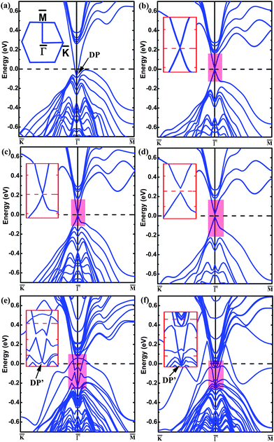 | ||
| Fig. 1 The band structures of Bi2Te2Se calculated for (a) the pristine 6QL-slab, (b) the O-substituted 6QL-slab, (c) the O-substituted 6QL-slab with no vacuum layer, (d) the O-substituted 4QL-slab, (e) the Cr-substituted 6QL-slab, and (f) the Mn-substituted 6QL-slab. The inset in panel (a) shows the 2D Brillouin zone, and those in (b)–(f) show zoomed-in views of the bands of the highlighted area. The Fermi level is indicated by the dashed line at 0 eV. | ||
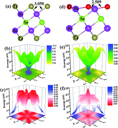 | ||
| Fig. 2 Comparison of the local structures and the 3D band structures around the Γ point calculated for the pristine and O-substituted (111) surfaces of Bi2Te2Se: (a) the optimized local structure, (b) the conduction band and (c) the valence band of the pristine (111) surface. (d) The optimized local structure, (e) the conduction band and (f) the valence band of the O-substituted (111) surface. The numbers in (a) and (d) are bond lengths in Å. The constant-energy contour plots are given at the bottom in (b), (c), (e) and (f). | ||
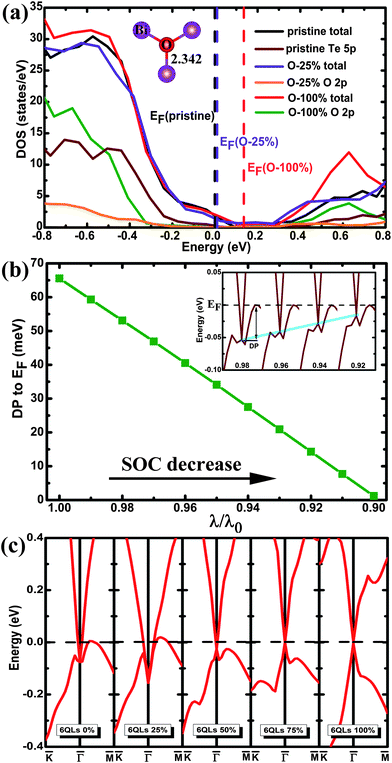 | ||
| Fig. 3 (a) The total and projected DOS plots calculated for the pristine and the O-substituted 6QL-slabs. To make the impurity states more visible, the values of the projected DOS values for the Te 5p and O 2p states are multiplied by a factor of 10. The vertical dashed lines denote the Fermi levels. All of the DOS plots are aligned by using the Te 5p states of the deepest QL layer. The inset shows the local structure of the O–Bi layer with 25% O substitution. (b) The relative distance between the Dirac point and the Fermi level (EF) as a function of the SOC strength (λ0 is the actual SOC strength). The inset shows the evolution of the Dirac point with different SOC strength. (c) The band structures calculated for the 6QL-slab with 0%, 25%, 50%, 75%, and 100% O-substitution in the outermost Te layers. The highest occupied and the lowest unoccupied bands are plotted to clearly show the evolution of the TSS states. The Fermi level is indicated by the dashed line at 0 eV. | ||
We now examine how the position of the Dirac point depends on the extent of the O substitution for Te by using the 6QL-slab of Bi2Te2Se. The band structures calculated for the 0%, 25%, 50%, 75%, and 100% O-substitutions of the outmost Te layers are summarized in Fig. 3(c). The pristine (111) surface (0% substitution) shows that the Dirac point is buried in the bulk valence band. For 25% substitution, a ‘V’-shaped Dirac cone forms at the top of the valence band with the Fermi level crossing the upper Dirac cone. For 50% substitution, the Fermi level no longer crosses the upper Dirac cone and the concave lower Dirac cone becomes convex. With greater than 50% substitution, the ideal Dirac cone, retaining the Kramers degeneracy at the Dirac point and the massless character, are obtained, and the position of the Dirac point at the Γ point moves upward with increasing the O coverage. As shown in Fig. 3(c), the position of the Dirac point does not depend monotonically on the O contents; initially it shifts downward and then upward. This is attributable to complex changes in O–Bi layers. For the 25% substitution a stronger O–Bi bonding occurs leading to a shorter O–Bi bond (2.342 Å), which lowers the O 2p states much more than the other cases (Fig. 3(a)). For the band structure of 4QL-slab that is the critical slab thickness to maintain the Dirac cone26 with 100% O-for-Te substitution, the major features of the Dirac cone are obtained but a tiny finite gap at the Dirac point appears as shown in Fig. 1(d). This is a direct result of the shorter Bi–O bond, and the coupling between the upper and the lower surface states becomes strong enough to open up this whole insulating gap.32,38,39
Now that the ideal Dirac cone with the in-gap Dirac point is obtained for the 6QL-slab with the O-substitution, its electronic structure can be modified further to create the IMDF state. For this purpose, we consider an additional Cr-substitution to break the TRS. First, we investigate the situation of Cr-substitution. The band structure of the (111) surface with the Cr-substitution, presented in Fig. 1(e), shows a band gap in the surface state near the original Dirac point but has one energy band crossing the Fermi level. A magnetic moment of 3.0 μB with out-of-plane spin orientation is introduced by Cr-substitution of Bi. A gap at the Dirac point appears because the surface electrons carry real spins and there are exchange interactions between the introduced magnetic impurities and the surface electrons. To study the magnetic order, two dopant Cr atoms are placed at two Bi sites in one QL with the smallest separation (about 2.83 Å). The total energies are calculated with SOC for the ferromagnetic (FM) and antiferromagnetic (AFM) spin arrangements (EFM and EAFM, respectively) to find that ΔE = EFM − EAFM is −159 meV (the calculations with different AFM configurations are checked and show the same result), which means that the FM state is the ground state. This is essential for many striking phenomena including the quantized anomalous Hall effect.9,10 To see the effect of co-substitution on the Dirac point, the band structure of the 6QL-slab with the Cr/O co-substitution is calculated and presented in Fig. 4(a). It shows a gap at the Dirac point, separating the upper and lower Dirac cones with the Fermi level located in both the surface and bulk band gaps, namely, the IMDF state is produced. It is interesting to note that a similar Dirac point at DP′ appears (Fig. 1(e) and Fig. 4(a)) although the magnetic impurity has exchange interactions with the surface electrons. This is very similar to the chemisorption of nonmagnetic impurity on the topological surface of Bi2Se3.30 The Cr-substitution only changes the electronic state of the topmost surface, and opens a gap for the corresponding Dirac point, while the electronic state at the other surface is unchanged and its Dirac point remains. As shown in Fig. 5(a) and (b), the charge density associated with the bands forming the Dirac point shows that the Dirac point originates mainly from the O and Se atoms on the outermost QL for the O substitution, but mainly from the Te and Bi atoms on the second QL for the Cr/O co-substitution. But for the bulk case with the Cr/O co-substitution, as shown in Fig. 4(a), a band (C1) formed above the Fermi level. The band decomposed charge density analysis show that the band originates mainly from the doped Cr atom and its first-shell neighbors (Fig. 5(c)).
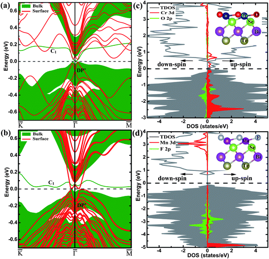 | ||
| Fig. 4 The electronic structures of Bi2Te2Se with the Cr/O and Mn/F co-substitutions. The band structures calculated for the (a) Cr/O co-substituted and (b) Mn/F co-substituted 6QL-slab with SOC, and their corresponding bulk band projections are represented by the shaded areas. The total and projected DOS plots for the 6QL-slab (c) with the Cr/O co-substitution and (d) with the Mn/F co-substitution without SOC, the shaded areas indicate the occupied states. The Fermi level is indicated by the dashed line at 0 eV. The insets in panels (c) and (d) show the side view of the outermost QLs with the Cr/O and Mn/F co-substitutions, respectively. | ||
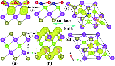 | ||
| Fig. 5 The charge density associated with the bands forming the Dirac point of 6QL-slab Bi2Te2Se with (a) the O-substitution and (b) the Cr/O co-substitution, and that associated with the band C1 of bulk Bi2Te2Se with (c) Cr/O co-substitution and (d) Mn/F co-substitution. | ||
To examine the magnetic property, the total DOS plot and the projected DOS plots calculated without SOC for the Cr 3d and O 2p states for the 6QL-slab with the Cr/O co-substitution are plotted in Fig. 4(c). The Cr 3d states are strongly spin-polarized, resulting in a high-spin d3 configuration with 3.0 μB per Cr. The up-spin 3d states of each Cr3+ ion located at an octahedral site are split into t2g↑ < eg↑, and the energy gap between the t2g↑ and eg↑ levels is large enough to accommodate the upper and lower Dirac cones inside this gap. Similar to the Fe adatoms on the surface of the TI Bi2Se3,40 calculations of the energy of the Cr/O co-substituted system as a function of the Cr spin-moment direction show that the ‖c spin-orientation is more stable than the ⊥c spin-orientation by 0.32 meV per Cr. Then the different degrees of Cr substitution for Bi with 100% O-for-Te substitution are investigated, and the IMDF states are formed for all cases (see Fig. 6).
 | ||
| Fig. 6 The band structures calculated for the Cr/O co-substituted 6QL-slab of Bi2Te2Se with (a) 25%, (b) 50%, and (c) 75% Cr-substitution and 100% O-substitution. The Fermi level is indicated by the dashed line at 0 eV. | ||
In the following, we show the realization of IMDF states without the ideal Dirac cone. As found in previous studies,41,42 the introduction of a Mn atom in Bi2Te2Se leads to a high-spin Mn3+ ion with moment 4.0 μB indicating the (t2g↑)3(eg↑)1 configuration for the Mn3+ ion, which has one hole in the up-spin 3d-states of Mn3+. For the case when two Mn ions have the smallest separation (about 2.76 Å), the FM spin arrangement is more stable than the AFM spin arrangement by 264 meV. Fig. 1(f) shows the band structure of the 6QL-slab with the Mn-substitution. As in the case of the 6QL-slab with the Cr-substitution, a band gap appears in the surface state near the Dirac point of the pristine surface. A new Dirac point occurs and the dispersion of the new surface states still keeps the nearly perfect ‘V’ shape. The hole of the up-spin 3d-states of Mn3+ is filled by the F/Mn co-substitution, and the magnetic moment increases to 5.0 μB. As shown in Fig. 4(b), this co-substitution introduces a band gap between the upper and lower Dirac cones of the pristine surface due to the loss of the TRS, and lowers the Fermi level so that it is now positioned inside the bulk and surface band gaps, with the similar Dirac point at DP′ and band (C1) appearing. In the substitution of F for Te, an F− ion replaces a Te2− ion. Each F atom requires one less electron than does Te from the Bi2Te2Se lattice, so the extra electron is transferred to a Mn3+ ion converting it to Mn2+ with electron configuration (t2g↑)3(eg↑)2. Thus, a gap between the spin-up and spin-down 3d-states of Mn2+ accommodates the upper and lower Dirac cones, as can be seen from Fig. 4(d) (collinear calculations without including SOC). As a result, the Mn/F co-substitution also induces an IMDF state into Bi2Te2Se. In addition, for the Mn/F co-substituted system, the ‖c spin-orientation is calculated to be more stable than the ⊥c spin-orientation (by 0.53 meV per Mn). We note that substitution of Fe for Bi, which induces the same magnetic moment as Mn/F co-substitution, cannot introduce the IMDF state. Therefore, the formation of the IMDF state is likely set by the TRS breaking disorder potential introduced on the surface and the interaction of magnetic atoms with the surface atoms.
Finally, we examine the feasibility of the Cr/O and Mn/F co-substitutions by calculating the defect formation energy Eform using the following equations:43
| Eform(M) = E(M-substituted) − E(pristine) + nBi(μBi − μM), |
| Eform(M/L) = E(M/L co-substituted) − E(pristine) + nBi(μBi − μM) + nTe(μTe − μL), |
 . The chemical potentials of bulk Cr, Mn, O, and F are used in the calculations. The calculated Eform values are summarized in Table 1 and Fig. 7 shows the difference of formation energies between M-substituted and M/L co-substitution, ΔEform = Eform(M/L) − Eform(M), in substituted Bi2Te2Se. They clearly show that the co-substitution of magnetic and nonmagnetic elements is energetically more favorable than the substitution of only a magnetic element under both Te-rich and Te-poor conditions, and thus the Cr/O and Mn/F co-substitutions are energetically favorable and the results are reasonable.
| Substitution | E f (eV) | |||
|---|---|---|---|---|
| Te-poor | Te-rich | M tot (μB) | ||
| a The bulk calculations employed the 60-atom supercell, and the surface calculations the 6QL-slab. | ||||
| Bulk | Cr | 0.823 | 0.082 | 3.0 |
| Cr/O | −0.352 | −0.352 | 3.0 | |
| Mn | 1.782 | 1.041 | 4.0 | |
| Mn/F | −2.721 | −2.721 | 5.0 | |
| Surface | Cr | 1.887 | 1.146 | 3.0 |
| Cr/O | 0.039 | 0.78 | 3.0 | |
| Mn | 1.904 | 1.163 | 4.0 | |
| Mn/F | −2.385 | −2.385 | 5.0 | |
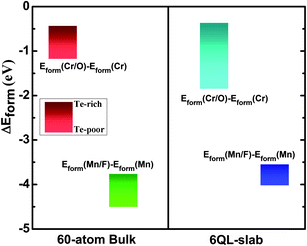 | ||
| Fig. 7 The difference of formation energies between M-substituted and M/L co-substitution, ΔEform = Eform(M/L) − Eform(M), in the bulk Bi2Te2Se and on the (111) surface of Bi2Te2Se. The bulk calculations employed the 60-atom supercell, and the surface calculations the 6QL-slab. | ||
IV. Conclusions
In summary, we showed that the IMDF state can be realized in ternary topological insulator Bi2Te2Se by introducing the Cr/O co-substitution or the Mn/F co-substitution on its surface QL. Our results can be summarized into three main points:(1) Bi2Te2Se possesses a highly insulating bulk band, but the Dirac point is buried in the bulk valence band. The O-substitution for the surface layer Te can raise the Dirac point to have an ideal Dirac cone with the in-gap Dirac point.
(2) The substitution Cr for Bi can induce a magnetic moment of 3.0 μB with out-of-plane spin orientation, break the time-reversal symmetry and open a gap at the Dirac point. Together with the O-substitution induced ideal Dirac cone, the IMDF state is formed by the Cr/O co-substitution.
(3) The introduction of F atom in Mn-doped Bi2Te2Se leads to an increase in the out-of-plane magnetic moment and a change in the interaction between the Mn and surface atoms. As a result, the Mn/F co-substitution also induces an IMDF state into Bi2Te2Se.
The co-substitution of magnetic and non-magnetic elements into topological insulators is a promising way of tailoring their electronic structures and properties. Recent experimental progresses have shown that various impurity elements (such as Cr, Mn, and O) can be substituted into the Bi-based topological insulators.6,41,44,45 The predictions of our proposed co-substitution, which can be prepared by the current technical capability of materials engineering, can be experimentally verifiable.
Acknowledgements
This work is supported by the National Basic Research Program of China (973 program, 2013CB632401), National Science Foundation of China under Grant 11174180 and 20973102, and the Natural Science Foundation of Shandong Province under Grant number ZR2011AM009, the Ministry of Education academic award for postgraduates. We also thank the National Supercomputer Center in Jinan for providing high performance computation.Notes and references
- J. E. Moore, Nature, 2010, 464, 194 CrossRef CAS.
- M. Hasan and C. Kane, Rev. Mod. Phys., 2010, 82, 3045 CrossRef CAS.
- X.-L. Qi and S.-C. Zhang, Rev. Mod. Phys., 2011, 83, 1057 CrossRef CAS.
- X.-L. Qi, T. L. Hughes and S.-C. Zhang, Phys. Rev. B: Condens. Matter, 2008, 78, 195424 CrossRef.
- C. Niu, Y. Dai, Z. Zhang, Y. Ma and B. Huang, Appl. Phys. Lett., 2012, 100, 252410 CrossRef.
- Y. L. Chen, J.-H. Chu, J. G. Analytis, Z. K. Liu, K. Igarashi, H.-H. Kuo, X. L. Qi, S. K. Mo, R. G. Moore, D. H. Lu, M. Hashimoto, T. Sasagawa, S. C. Zhang, I. R. Fisher, Z. Hussain and Z. X. Shen, Science, 2010, 329, 659 CrossRef CAS.
- J. Zang and N. Nagaosa, Phys. Rev. B: Condens. Matter, 2010, 81, 245125 CrossRef.
- X.-L. Qi, R. Li, J. Zang and S.-C. Zhang, Science, 2009, 323, 1184 CrossRef CAS.
- R. Yu, W. Zhang, H. J. Zhang, S. C. Zhang, X. Dai and Z. Fang, Science, 2010, 329, 61 CrossRef CAS.
- C. Niu, Y. Dai, L. Yu, M. Guo, Y. Ma and B. Huang, Appl. Phys. Lett., 2011, 99, 142502 CrossRef.
- R. Li, J. Wang, X.-L. Qi and S.-C. Zhang, Nat. Phys., 2010, 6, 284 CrossRef CAS.
- H. Zhang, C.-X. Liu, X.-L. Qi, X. Dai, Z. Fang and S.-C. Zhang, Nat. Phys., 2009, 5, 438 CrossRef CAS.
- Y. Xia, D. Qian, D. Hsieh, L. Wray, A. Pal, H. Lin, A. Bansil, D. Grauer, Y. S. Hor, R. J. Cava and M. Z. Hasan, Nat. Phys., 2009, 5, 398 CrossRef CAS.
- D. Hsieh, Y. Xia, D. Qian, L. Wray, J. H. Dil, F. Meier, J. Osterwalder, L. Patthey, J. G. Checkelsky, N. P. Ong, A. V. Fedorov, H. Lin, A. Bansil, D. Grauer, Y. S. Hor, R. J. Cava and M. Z. Hasan, Nature, 2009, 460, 1101 CrossRef CAS.
- Y. L. Chen, J. G. Analytis, J. H. Chu, Z. K. Liu, S. K. Mo, X. L. Qi, H. J. Zhang, D. H. Lu, X. Dai, Z. Fang, S. C. Zhang, I. R. Fisher, Z. Hussain and Z. X. Shen, Science, 2009, 325, 178 CrossRef CAS.
- J. Checkelsky, Y. Hor, M. H. Liu, D. X. Qu, R. Cava and N. Ong, Phys. Rev. Lett., 2009, 103, 246601 CrossRef CAS.
- Y. S. Hor, A. Richardella, P. Roushan, Y. Xia, J. Checkelsky, A. Yazdani, M. Hasan, N. Ong and R. Cava, Phys. Rev. B: Condens. Matter, 2009, 79, 195208 CrossRef.
- D. X. Qu, Y. S. Hor, J. Xiong, R. J. Cava and N. P. Ong, Science, 2010, 329, 821 CrossRef CAS.
- A. Taskin, Z. Ren, S. Sasaki, K. Segawa and Y. Ando, Phys. Rev. Lett., 2011, 107, 016801 CrossRef CAS.
- H. Peng, K. Lai, D. Kong, S. Meister, Y. Chen, X.-L. Qi, S.-C. Zhang, Z.-X. Shen and Y. Cui, Nat. Mater., 2010, 9, 225 CAS.
- J. Chen, H. Qin, F. Yang, J. Liu, T. Guan, F. Qu, G. Zhang, J. Shi, X. Xie, C. Yang, K. Wu, Y. Li and L. Lu, Phys. Rev. Lett., 2010, 105, 176602 CrossRef CAS.
- D. Kong, W. Dang, J. J. Cha, H. Li, S. Meister, H. Peng, Z. Liu and Y. Cui, Nano Lett., 2010, 10, 2245 CrossRef CAS.
- H. Steinberg, D. R. Gardner, Y. S. Lee and P. Jarillo-Herrero, Nano Lett., 2010, 10, 5032 CrossRef CAS.
- Z. Ren, A. Taskin, S. Sasaki, K. Segawa and Y. Ando, Phys. Rev. B: Condens. Matter, 2010, 82, 241306 CrossRef.
- S. Jia, H. Ji, E. Climent-Pascual, M. Fuccillo, M. Charles, J. Xiong, N. Ong and R. Cava, Phys. Rev. B: Condens. Matter, 2011, 84, 235206 CrossRef.
- J. Chang, L. Register, S. Banerjee and B. Sahu, Phys. Rev. B: Condens. Matter, 2011, 83, 235108 CrossRef.
- L.-L. Wang and D. Johnson, Phys. Rev. B: Condens. Matter, 2011, 83, 241309 CrossRef.
- K. Kuroda, M. Ye, A. Kimura, S. Eremeev, E. Krasovskii, E. Chulkov, Y. Ueda, K. Miyamoto, T. Okuda, K. Shimada, H. Namatame and M. Taniguchi, Phys. Rev. Lett., 2010, 105, 146801 CrossRef CAS.
- J.-H. Song, H. Jin and A. Freeman, Phys. Rev. Lett., 2010, 105, 096403 CrossRef.
- X. Wang, G. Bian, T. Miller and T. C. Chiang, Phys. Rev. Lett., 2012, 108, 096404 CrossRef.
- P. P. J. Haazen, J. B. Laloë, T. J. Nummy, H. J. M. Swagten, P. Jarillo-Herrero, D. Heiman and J. S. Moodera, Appl. Phys. Lett., 2012, 100, 082404 CrossRef.
- K. Park, J. Heremans, V. Scarola and D. Minic, Phys. Rev. Lett., 2010, 105, 186801 CrossRef.
- G. Kresse and J. Furthmüller, Phys. Rev. B: Condens. Matter, 1996, 54, 11169 CrossRef CAS.
- J. P. Perdew, K. Burke and M. Ernzerhof, Phys. Rev. Lett., 1996, 77, 3865 CrossRef CAS.
- S. L. Dudarev, G. A. Botton, S. Y. Savrasov, C. J. Humphreys and A. P. Sutton, Phys. Rev. B: Condens. Matter, 1998, 57, 1505 CrossRef CAS.
- P. Gopal and N. A. Spaldin, Phys. Rev. B: Condens. Matter, 2006, 74, 094418 CrossRef.
- H. Jin, J.-H. Song and A. Freeman, Phys. Rev. B: Condens. Matter, 2011, 83, 125319 CrossRef.
- Y. Y. Li, G. Wang, X. G. Zhu, M. H. Liu, C. Ye, X. Chen, Y. Y. Wang, K. He, L. L. Wang, X. C. Ma, H. J. Zhang, X. Dai, Z. Fang, X. C. Xie, Y. Liu, X. L. Qi, J. F. Jia, S. C. Zhang and Q. K. Xue, Adv. Mater., 2010, 22, 4002 CrossRef CAS.
- Y. Zhang, K. He, C.-Z. Chang, C.-L. Song, L.-L. Wang, X. Chen, J.-F. Jia, Z. Fang, X. Dai, W.-Y. Shan, S.-Q. Shen, Q. Niu, X.-L. Qi, S.-C. Zhang, X.-C. Ma and Q.-K. Xue, Nat. Phys., 2010, 6, 584 CrossRef.
- Z. Li, J. Yang, G. Chen, M. H. Whangbo, H. Xiang and X. Gong, Phys. Rev. B: Condens. Matter, 2012, 85, 054426 CrossRef.
- Y. S. Hor, P. Roushan, H. Beidenkopf, J. Seo, D. Qu, J. G. Checkelsky, L. A. Wray, D. Hsieh, Y. Xia, S. Y. Xu, D. Qian, M. Z. Hasan, N. P. Ong, A. Yazdani and R. J. Cava, Phys. Rev. B: Condens. Matter, 2010, 81, 195203 CrossRef.
- C. Niu, Y. Dai, M. Guo, W. Wei, Y. Ma and B. Huang, Appl. Phys. Lett., 2011, 98, 252502 CrossRef.
- S. B. Zhang and J. E. Northrup, Phys. Rev. Lett., 1991, 67, 2339 CrossRef CAS.
- D. Hsieh, Y. Xia, D. Qian, L. Wray, F. Meier, J. Dil, J. Osterwalder, L. Patthey, A. Fedorov, H. Lin, A. Bansil, D. Grauer, Y. Hor, R. Cava and M. Hasan, Phys. Rev. Lett., 2009, 103, 146401 CrossRef CAS.
- J. J. Cha, J. R. Williams, D. Kong, S. Meister, H. Peng, A. J. Bestwick, P. Gallagher, D. Goldhaber-Gordon and Y. Cui, Nano Lett., 2010, 10, 1076 CrossRef CAS.
| This journal is © The Royal Society of Chemistry 2013 |
