Electrochemical doping of anatase TiO2 in organic electrolytes for high-performance supercapacitors and photocatalysts†
Hui
Li
abcd,
Zhenhua
Chen
bd,
Chun Kwan
Tsang
bcd,
Zhe
Li
bcd,
Xiao
Ran
bcd,
Chris
Lee
bcd,
Biao
Nie
bcd,
Lingxia
Zheng
bcd,
Takfu
Hung
b,
Jian
Lu
*ef,
Bicai
Pan
*a and
Yang Yang
Li
*bcdgh
aDepartment of Physics, University of Science and Technology of China, Hefei, 230026, China. E-mail: bcpan@ustc.edu.cn
bCenter of Super-Diamond and Advanced Films (COSDAF), City University of Hong Kong, Kowloon, Hong Kong SAR. E-mail: yangli@cityu.edu.hk
cCenter for Functional Photonics, City University of Hong Kong, Kowloon, Hong Kong SAR
dDepartment of Physics and Materials Science, City University of Hong Kong, Kowloon, Hong Kong SAR
eDepartment of Mechanical and Biomedical Engineering, City University of Hong Kong, Kowloon, Hong Kong. E-mail: jianlu@cityu.edu.hk
fCentre for Advanced Structural Materials, City University of Hong Kong Shenzhen Research Institute, 8 Yuexing 1st Road, Shenzhen Hi-Tech Industrial Park, Nanshan District, Shenzhen, China
gUSTC-CityU Joint Advanced Research Centre, Suzhou, 215123, China
hCity University of Hong Kong Shenzhen Research Institute, 8 Yuexing 1st Road, Shenzhen Hi-Tech Industrial Park, Nanshan District, Shenzhen, China
First published on 28th October 2013
Abstract
In this article, we report a facile electrochemical method to modify anatase TiO2 by cathodically biasing TiO2 in an ethylene glycol electrolyte. The resulting black TiO2 is highly stable with a significantly narrower bandgap and higher electrical conductivity. Furthermore, largely improved photoconversion efficiency (increased from 48% to 72% in the visible region, and from nearly 0% to 7% in the UV region), photocatalytic efficiency, and charge-storage capability (∼42 fold increase) are achieved for the treated TiO2.
1. Introduction
TiO2 offers attractive technological advantages, e.g., high stability, low toxicity and wide commercial availability.1–3 It is currently being intensively studied for various applications in energy and environment areas, such as, photocatalysts, pollutant cleansers, supercapacitors, lithium ion batteries and solar cells.1,4–8 However, the native forms of TiO2 present considerable limitations, particularly a wide electronic bandgap (e.g., 3.0/3.2 eV for rutile/anatase) and a high resistivity.9–11 The wide bandgap of TiO2 limits its light harvesting ability in solar light. The high resistivity of TiO2 leads to high possibilities for electrons and holes to recombine when it is applied as a photocatalyst, and results in high internal resistance of the charge-storage devices when it is applied as an electro-active material. To address these limitations, focused efforts have been devoted to modify native TiO2.2,9–14 A common strategy is to dope native TiO2 with various impurity species (e.g., the nitrogen ions), e.g., by heating native TiO2 in a dopant-abundant atmosphere10,15–17 (e.g., NH3 or N2). However, the doped impurity atoms can serve as carrier recombination centers and decrease the overall photoconversion efficiency. Another strategy that has caught much attention lately is to self-dope TiO2 with the TiIII ions/oxygen vacancies,18–22 by for instance annealing TiO2 in a reductive/inert atmosphere or vacuum. The oxygen vacancies thus created can serve as shallow electron donors and increase carrier density, lowering the resistivity and facilitating charge transfer through an electrolyte/TiO2/charge collector. In general, the current techniques for doping native TiO2 largely focus on thermal annealing in a specific atmosphere at high temperature/pressure.Lately, it was found that TiO2 under cathodic bias is able to offer higher photocatalytic efficiency and capacitance, due to the field-driving interaction of small ions (H+ or Li+) which modifies the electronic structures of TiO2.23–26 However, the cathodically treated TiO2 reported to date suffers from low stability with the treatment effects fading away quickly upon removal of the bias (e.g., within minutes or hours).24,25 This low stability is possibly because the reported cathodic treatments were carried out in the low-viscosity aqueous electrolytes, which is in good agreement with a very recent study revealing that the dynamics of ion intercalation/release into/from TiO2 are highly dependent on the electrolyte viscosity.27
In this study we report electrochemical doping of anatase TiO2 in an ethylene glycol electrolyte through proton intercalation. Here TiO2 was synthesized by anodization2,5 for the benefit of growing TiO2 directly on the Ti substrate which readily serves as a charge collector in the doping treatment and the application tests (e.g., for solar cells and supercapacitors). The doped black TiO2 was highly stable with the beneficial effects persisting for over a year, and possessed a significantly narrower bandgap and higher conductivity. As a result, largely improved photoconversion efficiency, photocatalytic efficiency, and charge-storage capability were achieved for the doped TiO2 films. In particular, an ∼42 fold increase in specific capacitance was achieved for treated TiO2, representing a significant improvement from the previous study on TiO2 that was cathodically doped in an aqueous electrolyte (∼13 fold increase).28
2. Experimental section
2.1 Fabrication of anatase TiO2 nanotubes
The Ti substrates (0.25 mm thick, 99.7% purity, Sigma-Aldrich) were ultrasonically cleaned in acetone and ethanol successively and dried in a nitrogen stream before anodization. Anodic TiO2 films were generated in a two-electrode electrochemical cell, with a Pt gauze as the counter electrode and a Ti foil as the working anode. The Ti working anode was pressed together with an Al foil against an O-ring, defining a working area of 1.2 cm2. An ethylene glycol (less than 0.5 wt% H2O, International Laboratory USA) solution of 0.2 M HF (48 wt%, Riedel-de Haen) and 0.12 M H2O2 (35 wt%, Riedel-de Haen) was used as the electrolyte. Before use, the electrolyte was “aged” for 12 h at 60 V. A computer controlled Keithley 2400 Sourcemeter was used as the power source. Anodization was carried out with a constant voltage or current applied (typically, 80 V for 7200 s, or 4 mA for 5000 s). After anodization, the sample was rinsed with ethanol and DI water successively, and then dried in nitrogen. To obtain anatase TiO2 films, the as-anodized sample was thermally treated at 450 °C in air for 4 h.2.2 Electrochemical doping
The anatase TiO2 films first underwent a brief “activation” treatment (typically, at 60 V for 30 s, or 4 V for 600 s) in the anodization electrolyte mentioned above. A cathodic voltage (e.g., −40 V for 200 s) was then applied to electrochemically dope the sample in an ethylene glycol solution of 0.27 wt% NH4F (98+ wt%, Sigma-Aldrich).2.3 Characterization
Sample morphologies were examined with a field-emission scanning electron microscope (SEM) (JEOL 7001F) and a transmission electron microscope (TEM) (JEOL-2100F). Chemical compositional analysis was carried out using an EDX detector equipped with the TEM. The cross-sectional TiO2 nanotube sample for TEM measurements was prepared by first scraping the TiO2 nanotubular film off the Ti substrate. The nanotubular flakes thus obtained were dispersed in the epoxy resin. After curing at 60 °C for 24 h, the nanotubes fixed inside the epoxy resin were cut using an ultra-microtome. The thin (∼20 nm thick) slices thus produced were observed under the TEM.X-ray diffraction (XRD) patterns of the samples were collected using an X-ray diffractometer (Philips X'pert). Reflection spectra were measured using a diffuse reflectance UV-vis absorption spectrophotometer (Perkin Elmer Lambda λ750) equipped with an integrating sphere attachment. The spectra were recorded at room temperature from 200 to 800 nm, with the BaSO4 standard mirror used as the reference. Surface chemical analysis was carried out using an X-ray photoelectron spectrometer (XPS) (VG ESCALAB 220i-XL).
2.4 Photoconversion efficiency and conductivity measurements
The sample was soaked in the N719 dye solution for 12 h. The Ti/TiO2/N719 electrode, a 30 μm thick sealing spacer (Surlyn, Solaronix), and a Pt-coated counter electrode were assembled by hot-pressing. The redox pair used was iodide (I2−/Ix2−) with the following composition: 0.5 M LiI, 50 mM I2, and 0.5 M 4-tert-butylpyridine in 3-methoxypropionitrile (Fluka). The IPCE was then measured in a DC mode under mono-chromatic incident light of 1016 photons per cm2 from a 100 mW cm−2 white bias light source (CEP-2000, Bunko-Keiki). The EIS measurements were carried out on an electrochemical work station with a two-electrode system under 1 sun illumination, in a frequency range of 1 Hz to 100 kHz at a constant potential of 0.1 V and an AC voltage with 5 mV amplitude. Current density–voltage (J–V) characteristics of the solar cells were measured using a black metal mask with an aperture area of 0.23 cm2 under standard air mass 1.5 sunlight (100 mW cm−2, WXS-90S-L2, Wacom Denso).2.5 Photocatalytic measurements
The efficiency to photo-degrade Rhodamine (RB) was measured and used as an indicator of the photocatalytic ability of the TiO2 films. The concentration of RB as a function of the reaction time was calculated by monitoring the absorption maximum at 528 nm using a UV-vis spectrometer (Agilent UV-8453). The sample was immersed in an aqueous RB solution (20 ml) with the absorption measured to be 1.0 at 528 nm at the beginning. The exposed area of the film was fixed to be approximately 0.95 cm2. A high-pressure mercury lamp of 200 W was used as the illumination source with a filter to cut the light wavelength longer than 420 nm. The illumination intensity was measured to be 265 mW cm−2 at the sample surface.2.6 Electrochemical measurements for supercapacitor applications
Electrochemical measurements were performed at room temperature on a potentiostat (PAR Verastat 3) using a three-electrode configuration including a saturated calomel reference electrode, a platinum sheet (2 cm × 2 cm) as the counter electrode, and the sample as the working electrode. The electrolyte used was an aqueous solution of 0.5 M Na2SO4. CVs were measured from 0 V to 0.8 V with a scan rate of 100 mV s−1. The charge/discharge profiles were measured at a current density of 50, 100, 150, and 200 μA cm−2. Cycling stability was tested with a scan rate of 100 mV s−1 for 2000 cycles.3. Results and discussion
The sample fabrication procedures and conditions are shown in Fig. 1 and Table 1. Distinctly different colors (yellow, blue, and black) were observed for the as-anodized (after Step 1), as-annealed (after Step 2), and as-doped (after Step 4) films (Fig. 2a), respectively. The black appearance of the doped samples was found persistent for at least several months. The as-anodized TiO2 film featured self-aligned upright nanotubes standing vertically to the Ti substrate, as commonly observed in the literature.2,29–33 The atomic ratio of Ti to O along the radius direction was measured on a thin slice of freshly anodized nanotubes (Fig. 2b) using the EDX spectrometer equipped in the TEM. It was found that the Ti![[thin space (1/6-em)]](https://www.rsc.org/images/entities/char_2009.gif) :O ratio of the as-anodized nanotubes is approximately 1:1 (Fig. 2 table), indicating the abundant oxygen vacancies present in the as-anodized nanotubes, which is in good agreement with the previous studies.9,34
:O ratio of the as-anodized nanotubes is approximately 1:1 (Fig. 2 table), indicating the abundant oxygen vacancies present in the as-anodized nanotubes, which is in good agreement with the previous studies.9,34
 | ||
| Fig. 1 Fabrication procedures used in this study for generating doped black TiO2 nanotubes. | ||
| Anatase TiO2 synthesis | Electrochemical doping | Application study | |||
|---|---|---|---|---|---|
| Step 1, anodization | Step 2, annealing | Step 3, activation | Step 4, cathodic doping | ||
| Sample A0 | 80 V, 7200 s | 450 °C, 4 h | NA | NA | Photocatalysis solar cell |
| Sample A1 | NA | −40 V, 680 s | |||
| Sample A2 | 60 V, 30 s | ||||
| Sample B0 | 4 mA, 5000 s | NA | NA | Supercapacitor | |
| Sample B1 | NA | −40 V, 200 s | |||
| Sample B2 | 4 V, 600 s | ||||
| Sample B3 | −40 V, 200 s, then −20 V, 300 s | ||||
 | ||
| Fig. 2 (a) Optical photographs of the TiO2 films (Sample A2) after different steps shown in Table 1: “as-anodized” (after Step 1); “as-annealed” (after Step 2); “as-doped” (after Step 4). (b) TEM image of a slice of the as-anodized TiO2 nanotubes (anodized at 80 V for 7200 s). The table shows the atomic compositions of Ti and O, measured along the radius direction of the nanotubes (indicated by the purple arrow shown in the TEM image). | ||
The as-anodized sample (after Step 1) was amorphous,35 indicated by the XRD measurement (Fig. 3). Previous research has shown that the anatase phase greatly outperforms the amorphous phase for application purposes (e.g., photocatalysts).2,36 In light of this, thermal annealing was applied to convert the as-anodized TiO2 samples from the amorphous phase into anatase (Step 2) (Fig. 3). The annealed TiO2 film was further “activated” (Step 3) at an anodic voltage (e.g., 4 V) for a short period of time (e.g., 600 s), and cathodically doped (Step 4). The as-doped TiO2 film had its self-ordered nanotubular morphology preserved. More importantly, the film remained anatase with no deterioration in crystallinity detected after the electrochemical doping treatments (Fig. 3), which proved to be particularly beneficial for the photocatalyst and supercapacitor applications, and will be discussed in a later section of this paper.
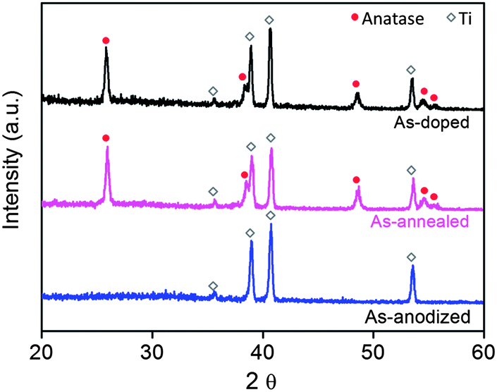 | ||
| Fig. 3 XRD patterns of the as-anodized (anodized at 80 V for 2 h), as-annealed (Sample A0), and as-doped (Sample A2) samples. | ||
The XPS measurements were carried out to investigate the surface chemistry states of the as-annealed and as-doped TiO2. The Ti 2p spectra of the as-annealed and the as-doped TiO2 showed no detectable difference (Fig. S1†), indicating that the TiIII species were possibly present deep inside the bulk rather than on the surface. Previous research has shown that the TiIII species are not stable on the surface and their existence in the bulk is a key factor determining the stability of the doped TiO2.14 On the other hand, the O 1s spectra (Fig. 4a) exhibited significant differences; the peaks of the as-annealed sample were symmetric whereas those of the as-doped sample were apparently asymmetric. For the doped sample, the O 1s peak located at 530.6 eV can be assigned to the lattice oxygen of TiO2,37 and there were two new shoulder peaks at higher binding energies of 531.1 eV and 532.4 eV (Fig. 4a). The peak at 531.1 eV can be attributed to an acidic hydroxyl group, while the 532.4 eV can be assigned to a basic hydroxyl group38,39 which was reported to locate at ∼1.5 to 1.8 eV higher than the O 1s peak of the lattice oxygen. Therefore, the XPS measurements revealed the formation of acidic and basic hydroxyl groups on the sample surface.
 | ||
| Fig. 4 (a) O 1s XPS spectra of the as-annealed (Sample A0) and as-doped (Sample A2) samples with the experimental results shown by thick purple and black curves and the fitted peaks shown by the thin blue lines. (b) Valance-band XPS spectra of the as-annealed (Sample A0) and as-doped (Sample A2) samples. The linear extrapolation of the peak to the baseline indicates the valence band maximum. | ||
For the valence-band (VB) XPS spectra (Fig. 4b), the VB maxima were estimated by linearly extrapolating the peaks to the baselines. The VB maximum was 3.1 eV below the zero point of potential energy for the as-doped sample, and 3.6 eV for the as-annealed sample. The upshift of the VB maximum suggested the formation of defects in the doped sample, which induced donor energy states close to the VB maximum.11
According to the XPS observation, the following doping mechanism is proposed (eqn (1)–(3)):
![[triple bond, length as m-dash]](https://www.rsc.org/images/entities/char_e002.gif) TiIV–O–TiIV + H3O+ + e− → TiIII–OH2 + TiIV–OH TiIV–O–TiIV + H3O+ + e− → TiIII–OH2 + TiIV–OH | (1) |
| TiIV–OH + H3O+ + e− → TiIII–OH2 + H2O | (2) |
| TiIV–OH + e− → TiIII–OH | (3) |
Note that TiIII–OH is basic and TiIII–OH2 is acidic.
The mechanism of cathodic doping reported here is similar to the electrochromatic mechanism of TiO2. TiO2 is well known to undergo a color change to black or dark blue under cathodic bias in an aqueous solution. The color change is due to the insertion of small cations under cathodic bias. The TiIII species generated are accountable for the light absorption of TiO2 in the visible region, although the electrochromatic mechanism has not yet been fully understood.40,41
Note that the electrochromatic studies on TiO2 reported to date are generally carried out in aqueous systems with the dark-colored state quickly vanishing upon removal of the cathodic bias (usually within seconds).40 However, the cathodic doping in the EG system reported in this study is highly stable and the samples remained black for at least several months after the doping treatment. This higher stability can be attributed to the following factors. First, the application of the organic solvent allows for high voltage to be applied without solvent breakdown, providing a high driving force for the hydrogen ions to diffuse deeper into TiO2. Second, because only a trace amount of H2O is present in the EG electrolyte, H+ ions are gradually produced at a low concentration through electrolysis of H2O. Due to such a low concentration of H+ ions present at the TiO2 electrode surface, it is difficult for them to undergo reduction and recombine into hydrogen gas. Therefore, it is more likely for the H+ ions to be driven inside the TiO2 under the cathodic field. Third, the EG electrolyte possibly provides the proper viscosity for the H species to migrate and insert into TiO2. For comparison, when glycerol was used as the solvent, it was found that the TiO2 sample turned black when cathodically biased, but the black color quickly faded within several seconds after the removal of the cathodic bias. The observed lower stability for samples doped in glycerol than in EG is possibly because glycerol has a higher viscosity making it difficult for the protons to insert into TiO2. This observation is in good agreement with the recent report that reveals that the electrolyte viscosity has a significant impact on the dynamics of the intercalation/release of the small ions into/from TiO2.27 Fourth, the “activation” step before the cathodic doping removes the oxide debris on top of nanotube arrays (commonly called “nanograss”),42 providing easy access for the H+ ions to diffuse/replenish within the nanotubes. Meanwhile, during this “activation” step, the F− ions diffuse inside the skin layers of the nanotubes and form [TiF6]2− ions. These ions are then repelled in the later doping step by the cathodic field and dissolve, providing pathways for H+ ions during the aforementioned step.
The Electrochemical Impedance Spectra (EIS) measurement is a powerful tool for studying the interfacial properties between electrodes and solutions.43 To further characterize the electrical properties of the as-doped TiO2 samples, EIS measurements were carried out under illumination. Fig. 5 presents the Nyquist plots of the as-annealed (Sample B0) and as-doped (Sample B3) TiO2 samples measured in an assembled TiO2/N719/electrolyte/Pt cell, with the equivalent circuit diagram shown in the inset. The similar semicircular arcs in the EIS plot were observed for both the doped and non-doped TiO2 samples at high-frequency. The high frequency region usually reflects the charge transfer resistance at the counter electrode–electrolyte interface and has little dependency on the working electrode (TiO2). On the other hand, the second arc in the mid-frequency region reflects the diffusion impedance in the electrolyte and highly depends on the resistance of the TiO2 nanotube/dye/electrolyte interfaces.43 Calculation shows that the resistance of the doped TiO2 sample was much lower than the non-doped one (Fig. 5 table), which indicates a faster charge transfer and a smaller interfacial resistance for the doped sample. The increased conductivity of doped TiO2 can be attributed to the oxygen vacancies produced. Oxygen vacancies in TiO2 are known to be shallow electron donors and can facilitate the transport of charge carriers.19,44
 | ||
| Fig. 5 Nyquist plots for Sample A0 and Sample A2. The two main semicircular shapes are assigned to the impedance related to charge transport at the Pt counter electrode at high-frequency (Z1) and the diffusion impedance in the electrolyte in medium frequency (Z2). The equivalent circuit diagram of the device is shown in the inset. R1 and R2 are the real parts of Z1 and Z2, respectively. Rh is the resistance of the Ti substrate at high frequency. Series resistance of the cell is denoted as R: R = Rh + R1 + R2. The calculated resistances of the samples are listed in the table. | ||
In order to evaluate the photoconversion efficiency of doped TiO2, the monochromatic incident photon-to-electron conversion efficiency (IPCE) was measured in the sandwiched TiO2/N719/electrolyte/Pt cell (Fig. 6). At 536 nm, the peak IPCE was measured to be 48% for the as-annealed TiO2 sample (Sample A0), and 72% for the as-doped sample with the “activation” pretreatment (Sample A2), representing a dramatic increase of 50%. Notably, for the sample doped without the “activation” pretreatment (Sample A1), a less dramatic increase of IPCE (60%) was obtained, indicating the necessity of applying the “activation” pretreatment before cathodic doping. More importantly, a remarkable enhancement in the IPCE from nearly 0% up to 7% was achieved for the doped sample (Sample A2) in the UV region, indicating much improved utilization of UV light. The current density–voltage (J–V) analysis (Fig. 7) on the aforementioned assembled cells showed good consistency with the IPCE measurements. A similar descending sequence of the short circuit current density, Jsc, was observed: Sample A2 > Sample A1 > Sample A0.
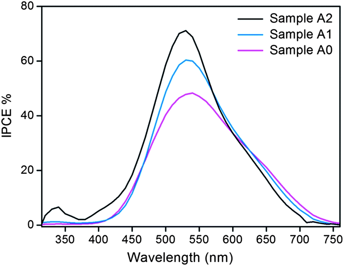 | ||
| Fig. 6 IPCE spectra of the cells assembled with Samples A0, A1 and A2. | ||
 | ||
| Fig. 7 J–V characteristics of the solar cells based on Samples A0, A1, and A2 with the cell performance parameters listed in the table. | ||
The dramatic increase in IPCE for the doped TiO2 can be explained by examining the following three factors (eqn (4)): the light harvesting energy efficiency (LHE), the quantum yield of injection efficiency (ϕinj), and the charge collection efficiency (ηc):45
| IPCE = LHE × ϕinj × ηc | (4) |
Note that N719 has two characteristic absorption peaks with the stronger one located at 536 nm and the weaker one located at 340 nm.46 Previous research shows that the presence of the surface hydroxyl groups can facilitate the adsorption of the N719 dye molecules. As a result, the as-doped sample is able to adsorb more N719 molecules due to its production of Ti–OH on the surface (eqn (1)–(3)), leading to a higher LHE. Moreover, the doped sample has a much higher absorption of the UV and visible light (Fig. S2†), allowing the adsorbed dyes to harvest more light and leads to a higher LHE. Meanwhile, it was found from the DSC J–V curves (Fig. 7) that the open voltage decreased after the doping treatment, indicating the downshift of the conduction band (CB) minimum for the doped samples. On the other hand, the VB XPS revealed the upshift (by 0.5 eV) of the VB maximum for the doped samples (Fig. 4b). Therefore, bandgap narrowing was achieved for doped TiO2, which enables higher LHE. As to the quantum yield of injection efficiency (ϕinj), because of the downshift of the CB minimum after doping, the energy difference between the CB minima of TiO2 and the dye molecule is larger for the doped samples, leading to a higher ϕinj. Regarding the charge collection efficiency, ηc, it is generally considered being very high for the system based on N719 and TiO2.46 Nevertheless, the lower resistivity of doped TiO2 can further increase ηc of the device. Moreover, the increased electron density from the oxygen vacancies in doped TiO2 will cause the Fermi level to upshift toward the CB.44,47 This, in turn, will enhance band bending at the TiO2–Ti interface and facilitate the charge separation at the interface, resulting in a higher ηc.
The photocatalytic effectiveness of doped TiO2 was evaluated by measuring its efficiency in the photo-degradation of RB. RB is a non-biodegradable dye that is commonly used in textile and paper industries. When irradiating TiO2 with photons whose energy is higher than its bandgap, holes and electron pairs can be created and react with H2O and O2 on the surface of TiO2. These reactions generate highly reactive hydroxyl radicals (˙OH) and superoxide anion radicals (O2−) that can degrade organic molecules.4,48Fig. 8 shows the degradation curves of RB for the as-anodized samples, Sample A0, and Sample A2. The control experiment (in the absence of any photocatalyst) revealed that the dye degradation under UV illumination was almost negligible. It should be pointed out that, although rich in oxygen vacancies (Fig. 2 table), the as-anodized sample showed dramatically lower photodegrading efficiency compared to the anatase samples (Samples A0 and A2), which is in good agreement with previous studies.2,35 Predictably, Sample A2 showed the highest photocatalytic efficiency among the samples tested.
 | ||
| Fig. 8 Ratio of the actual and initial concentrations (C/C0) of RB as a function of the UV illumination time for the as-anodized sample (anodized at 80 V for 7200 s), Sample A0, and Sample A2. The blank experiment was carried out in the absence of any photocatalyst (“no photocatalyst”). | ||
The improved efficiency of doped TiO2 (Sample A2) can be ascribed to several factors. First, the doped TiO2 exhibited much higher absorption of UV and visible light, as evidenced by the much lower reflectance observed in the diffuse reflectance spectra (Fig. S2†) and the dramatic color change from pale-yellow to black after the doping treatment. Second, the generated oxygen vacancies/TiIII species (eqn (1)–(3)), and the reduced resistivity (Fig. 5), as a result of electrochemical doping, are all helpful to reduce the charge carrier recombination rate. Another factor accountable for the improved efficiency is the additional electronic states created by the oxygen vacancies and the TiIII species inside the bandgap, which enable shorter electron excitation routes with lower possibility for charge recombination. The improved photocatalytic efficiency under UV illumination is in good agreement with the IPCE measurements (Fig. 6), which showed that a dramatic increase from nearly 0% to 7% in the UV region was achieved after the doping treatment.
Recently, supercapacitors based on transition metal oxides have attracted significant attention due to their high specific capacitance, high stability, and low toxicity.49 In this study, a dramatic improvement in supercapacitor performance was observed after the doping treatment. The cyclic voltammetry (CV) study was performed on the different TiO2 samples (Samples B0, B1, B2, and B3, Fig. 9a). The CV curve of the as-annealed sample (Sample B0) displayed the smallest enclosed area, while Samples B1, B2, and B3 displayed a successively increased enclosed area. The dramatic increase in the CV area from Sample B0 to Sample B3 revealed a remarkable improvement in power storage capability – a result of the doping treatment. Furthermore, nearly rectangular-shaped CV curves, as expected for an ideal capacitor,50 were observed for all the doped samples (Samples B1–B3). Interestingly, the two-step cathodic doping (−40 V for 200 s followed by −20 V for 300 s, Sample B3) was found to give the largest enclosed area of the CV curve.
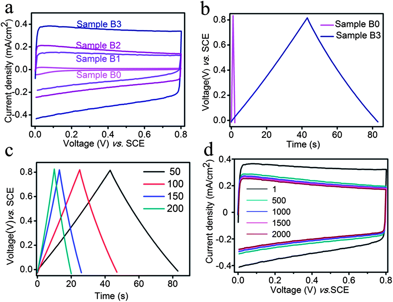 | ||
| Fig. 9 (a) First loop cyclic voltammograms (scan rate of 100 mV s−1) for Samples B0, B1, B2, and B3. (b) Cyclic chronopotentiometry curves of Sample B0 and Sample B3 measured at a charge/discharge current density of 50 μA cm−2. (c) Chronopotentiometry curves of Sample B3 at different discharge current densities of 50 μA cm−2, 100 μA cm−2, 150 μA cm−2, and 200 μA cm−2. (d) Cyclic voltammograms (scan rate of 100 mV s−1) of Sample B3 up to 2000 cycles. | ||
The electrochemical performance of the TiO2 samples was further studied by galvanostatic charge/discharge measurements (Fig. 9b). It can be seen from the measurements at 50 μA cm−2 that a dramatic improvement (a 42 fold increase) in specific capacitance (SC) was achieved through the doping treatment: the SCs for Samples B3 and B0 are 2.63 and 0.0625 mF cm−2, respectively. Galvanostatic measurements on Sample B3 revealed its area-specific capacitance to be 2.63, 3.00, 2.03, and 2.10 mF cm−2 at the current density of 50, 100, 150, and 200 μA cm−2 (Fig. 9c), respectively, indicating the good rate-retention capacity of doped-TiO2. Moreover, the high stability of the doped sample was evidenced by the fact that the dramatically improved charge-storage capability remained after 2000 CV cycles (Fig. 9d), i.e., the enclosed area of the CV curve at the 2000th cycle remained much larger than the as-annealed sample.
The observed enhancement in the electrochemical performance of the doped TiO2 samples can be attributed to their high conductivities (Fig. 5). Furthermore, previous studies show that hydrogenation of TiO2 leads to an increased density of hydroxyl groups on the surface of TiO2, resulting in an enhanced specific capacitance.21 Similarly, we have produced samples that display an increased density of hydroxyl groups generated on the surface of TiO2 by cathodic doping (eqn (1)–(3)), which can also contribute to the increased specific capacitance. Moreover, pathways for the insertion/release of the H species are created during the preceding doping treatment of TiO2, which are likely to facilitate the insertion/release of H+ ions to/from TiO2 when it is used as an electro-active material in supercapacitors.
4. Conclusion
In conclusion, we have presented a facile electrochemical method for doping anatase TiO2 in ethylene glycol. The highly stable black TiO2 thus produced is self-doped with oxygen vacancies and possesses a significantly narrower bandgap and lowered resistivity. The electrochemical doping method reported here is particularly convenient for generating high-performance TiO2 materials for a wide-range of applications (e.g., photocatalysts or supercapacitors). It should also be pointed out that the doping method reported here enables novel energy-efficient electrochromatic systems that can stay at the color-state for extremely long time without consuming any electrical power. Furthermore, the method reported here can be potentially applied to modify other anodic metal oxides (e.g., Ta2O3, ZrO2, Nb2O5, WO3 and Fe2O3) for improved properties.Acknowledgements
This work was supported by the National Key Basic Research Program of the Chinese Ministry of Science and Technology (Project 2012CB932203), the National Natural Science Foundation of China (Project 51202206), and the City University of Hong Kong (Projects 9667070 and 7003039).Notes and references
- S. Liu, Z. Wang, C. Yu, H. B. Wu, G. Wang, Q. Dong, J. Qiu, A. Eychmüller and X. W. Lou, Adv. Mater., 2013, 25, 3462–3467 CrossRef CAS PubMed.
- P. Roy, S. Berger and P. Schmuki, Angew. Chem., Int. Ed., 2011, 50, 2904–2939 CrossRef CAS PubMed.
- X. Chen and S. S. Mao, Chem. Rev., 2007, 107, 2891–2959 CrossRef CAS PubMed.
- A. Fujishima and K. Honda, Nature, 1972, 238, 37–38 CrossRef CAS.
- A. Ghicov and P. Schmuki, Chem. Commun., 2009, 2791–2808 RSC.
- P. Yang, X. Zhou, G. Cao and C. K. Luscombe, J. Mater. Chem., 2010, 20, 2612–2616 RSC.
- M. Ye, H.-Y. Liu, C. Lin and Z. Lin, Small, 2013, 9, 312–321 CrossRef CAS PubMed.
- J. S. Chen, C. Chen, J. Liu, R. Xu, S. Z. Qiao and X. W. Lou, Chem. Commun., 2011, 47, 2631–2633 RSC.
- M. Salari, K. Konstantinov and H. K. Liu, J. Mater. Chem., 2011, 21, 5128–5133 RSC.
- R. Asahi, T. Morikawa, T. Ohwaki, K. Aoki and Y. Taga, Science, 2001, 293, 269–271 CrossRef CAS PubMed.
- X. Chen, L. Liu, P. Y. Yu and S. S. Mao, Science, 2011, 331, 746–750 CrossRef CAS PubMed.
- F. Zuo, L. Wang, T. Wu, Z. Zhang, D. Borchardt and P. Feng, J. Am. Chem. Soc., 2010, 132, 11856–11857 CrossRef CAS PubMed.
- G. Liu, H. G. Yang, X. Wang, L. Cheng, H. Lu, L. Wang, G. Q. Lu and H.-M. Cheng, J. Phys. Chem. C, 2009, 113, 21784–21788 CAS.
- A. Naldoni, M. Allieta, S. Santangelo, M. Marelli, F. Fabbri, S. Cappelli, C. L. Bianchi, R. Psaro and V. Dal Santo, J. Am. Chem. Soc., 2012, 134, 7600–7603 CrossRef CAS PubMed.
- R. P. Vitiello, J. M. Macak, A. Ghicov, H. Tsuchiya, L. F. P. Dick and P. Schmuki, Electrochem. Commun., 2006, 8, 544–548 CrossRef CAS PubMed.
- X. Chen and C. Burda, J. Am. Chem. Soc., 2008, 130, 5018–5019 CrossRef CAS PubMed.
- J. M. Macak, A. Ghicov, R. Hahn, H. Tsuchiya and P. Schmuki, J. Mater. Res., 2006, 21, 2824–2828 CrossRef CAS.
- G. Wang, Y. Ling and Y. Li, Nanoscale, 2012, 4, 6682–6691 RSC.
- J. M. Macak, B. G. Gong, M. Hueppe and P. Schmuki, Adv. Mater., 2007, 19, 3027–3031 CrossRef CAS.
- Z. Zheng, B. Huang, J. Lu, Z. Wang, X. Qin, X. Zhang, Y. Dai and M.-H. Whangbo, Chem. Commun., 2012, 48, 5733–5735 RSC.
- X. Lu, G. Wang, T. Zhai, M. Yu, J. Gan, Y. Tong and Y. Li, Nano Lett., 2012, 12, 1690–1696 CrossRef CAS PubMed.
- G. Wang, H. Wang, Y. Ling, Y. Tang, X. Yang, R. C. Fitzmorris, C. Wang, J. Z. Zhang and Y. Li, Nano Lett., 2011, 11, 3026–3033 CrossRef CAS PubMed.
- F. Fabregat-Santiago, E. M. Barea, J. Bisquert, G. K. Mor, K. Shankar and C. A. Grimes, J. Am. Chem. Soc., 2008, 130, 11312–11316 CrossRef CAS PubMed.
- B. H. Meekins and P. V. Kamat, ACS Nano, 2009, 3, 3437–3446 CrossRef CAS PubMed.
- J. Idígoras, T. Berger and J. A. Anta, J. Phys. Chem. C, 2012, 117, 1561–1570 Search PubMed.
- C. Xu, Y. Song, L. Lu, C. Cheng, D. Liu, X. Fang, X. Chen, X. Zhu and D. Li, Nanoscale Res. Lett., 2013, 8, 391 CrossRef PubMed.
- W. Song, H. Luo, K. Hanson, J. J. Concepcion, M. K. Brennaman and T. J. Meyer, Energy Environ. Sci., 2013, 6, 1240–1248 CAS.
- H. Zhou and Y. Zhang, J. Power Sources, 2013, 239, 128–131 CrossRef CAS PubMed.
- H. Li, J. Zhang, J.-W. Cheng, Z. H. Chen, F. Liang, C. K. Tsang, H. Cheng, L. Zheng, S.-T. Lee and Y. Y. Li, ECS J. Solid State Sci. Technol., 2012, 1, M6–M9 CrossRef CAS PubMed.
- G. K. Mor, O. K. Varghese, M. Paulose, K. Shankar and C. A. Grimes, Sol. Energy Mater. Sol. Cells, 2006, 90, 2011–2075 CrossRef CAS PubMed.
- H. Li, L. Zheng, S. Shu, H. Cheng and Y. Y. Li, J. Electrochem. Soc., 2011, 158, C346–C351 CrossRef CAS PubMed.
- J. M. Macak, H. Tsuchiya, A. Ghicov, K. Yasuda, R. Hahn, S. Bauer and P. Schmuki, Curr. Opin. Solid State Mater. Sci., 2007, 11, 3–18 CrossRef CAS PubMed.
- V. Zwilling, M. Aucouturier and E. Darque-Ceretti, Electrochim. Acta, 1999, 45, 921–929 CrossRef CAS.
- H. Li, J.-W. Cheng, S. Shu, J. Zhang, L. Zheng, C. K. Tsang, H. Cheng, F. Liang, S.-T. Lee and Y. Y. Li, Small, 2013, 9, 37–44 CrossRef CAS PubMed.
- X. Chen, M. Schriver, T. Suen and S. S. Mao, Thin Solid Films, 2007, 515, 8511–8514 CrossRef CAS PubMed.
- J. Yu, H. Yu, B. Cheng and C. Trapalis, J. Mol. Catal. A: Chem., 2006, 249, 135–142 CrossRef CAS PubMed.
- L. Deng, S. Wang, D. Liu, B. Zhu, W. Huang, S. Wu and S. Zhang, Catal. Lett., 2009, 129, 513–518 CrossRef CAS.
- J. S. Dalton, P. A. Janes, N. G. Jones, J. A. Nicholson, K. R. Hallam and G. C. Allen, Environ. Pollut., 2002, 120, 415–422 CrossRef CAS.
- K. E. Healy and P. Ducheyne, Biomaterials, 1992, 13, 553–561 CrossRef CAS.
- A. Ghicov, H. Tsuchiya, R. Hahn, J. M. Macak, A. G. Muñoz and P. Schmuki, Electrochem. Commun., 2006, 8, 528–532 CrossRef CAS PubMed.
- A. Ghicov, M. Yamamoto and P. Schmuki, Angew. Chem., Int. Ed., 2008, 47, 7934–7937 CrossRef CAS PubMed.
- D. Kim, A. Ghicov and P. Schmuki, Electrochem. Commun., 2008, 10, 1835–1838 CrossRef CAS PubMed.
- L. Han, N. Koide, Y. Chiba and T. Mitate, Appl. Phys. Lett., 2004, 84, 2433–2435 CrossRef CAS.
- A. Janotti, J. B. Varley, P. Rinke, N. Umezawa, G. Kresse and C. G. Van de Walle, Phys. Rev. B: Condens. Matter Mater. Phys., 2010, 81, 085212 CrossRef.
- Z. Chen, W. Peng, K. Zhang, J. Zhang, M. Yanagida and L. Han, Nanoscale, 2012, 4, 7690–7697 RSC.
- S. Zhang, X. Yang, Y. Numata and L. Han, Energy Environ. Sci., 2013, 6, 1443–1464 CAS.
- Y. H. Hu, Angew. Chem., Int. Ed., 2012, 51, 12410–12412 CrossRef CAS PubMed.
- M. R. Hoffmann, S. T. Martin, W. Choi and D. W. Bahnemann, Chem. Rev., 1995, 95, 69–96 CrossRef CAS.
- J. Jiang, Y. Li, J. Liu, X. Huang, C. Yuan and X. W. Lou, Adv. Mater., 2012, 24, 5166–5180 CrossRef CAS PubMed.
- A. L. M. Reddy and S. Ramaprabhu, J. Phys. Chem. C, 2007, 111, 7727–7734 CAS.
Footnote |
| † Electronic supplementary information (ESI) available. See DOI: 10.1039/c3ta13963h |
| This journal is © The Royal Society of Chemistry 2014 |