DOI:
10.1039/C3TA11827D
(Paper)
J. Mater. Chem. A, 2013,
1, 11355-11367
Received
9th May 2013
, Accepted 16th July 2013
First published on 17th July 2013
Abstract
In this study, a novel mixed Ce–Fe oxide decorated multiwalled carbon nanotubes (CF-CNTs) material was prepared through a surfactant assisted method. The CF-CNTs material was characterized by various methods, including BET surface area analysis, transmission electron microscopy (TEM), X-ray diffraction (XRD), Fourier transform infrared spectroscopy (FTIR) and X-ray photoelectron spectroscopy (XPS). It was found that the Ce–Fe oxide was uniformly dispersed on the surface of CNTs with a mean size of 7.0 nm. The obtained CF-CNTs material was used as an adsorbent to remove arsenic from aqueous solutions. The adsorption experimental results showed that this CF-CNTs material had an excellent adsorption performance for As(V) and As(III). The adsorption processes of As(V) and As(III) could be well described by the pseudo-second-order model. The mechanistic study showed that different interactions were involved in As(V) adsorption, including electrostatic attraction and surface complexation. For As(III) adsorption, partial As(III) was oxidized to As(V) followed by the simultaneous adsorption of As(V) and As(III). It was also found that intra-particle diffusion existed in the process of adsorption on CF-CNTs, but that it was not the only rate-limiting step. The resulting CF-CNTs material can be used in a broad pH range, which suggests its great potential for the decontamination of arsenic-polluted water.
1 Introduction
The widespread occurrence of arsenic contamination in groundwater, which is attributed to mineral leaching and anthropogenic activities, is considered as one of the most serious environmental problems, and the harmful consequences of arsenic on human health are well established.1–5 In a typical aquatic environment, arsenic predominantly exists in two different oxidation states, As(V) and As(III).6 Under natural environmental conditions, As(V) mainly exists in anionic species, including H2AsO4− and HAsO42−, while As(III) is more toxic than As(V) and usually exists as H3AsO3. More importantly, As(III) is more mobile than As(V) and is more difficult to remove by adsorption technology.
A wide range of adsorbents have been studied to remove arsenic, including natural minerals, traditional active carbon, bimetal oxides, surface modified materials, biomasses and nanoparticle materials.7 Among them, iron-based adsorbents, such as various iron ores,8–10 granular ferric hydroxide,11 hydroxy iron oxides,12 and iron-containing granular materials,13 have been paid more attention to due to their high capacity for arsenic removal. Bimetal oxides, by incorporating some other metal elements such as Zr, Ti, Ce, Co and Mn, into iron oxides have shown a superior performance of arsenic adsorption.14–18 Novel metal oxide modified composites are another category of adsorbents with superior performance. Decorating the active carbon, mesoporous carbon matrix, carbon nanotubes (CNTs), carbon nanofibers, graphite and graphene with iron oxides can significantly improve the arsenic uptake performance.19–23 Composites with a high specific surface area and uniformly dispersed iron oxides can be used as ideal materials for arsenic removal with the advantages of large capacity, fast adsorption, easy operation, and long cyclic stability.24
Since their discovery by Iijima in 1991,25 CNTs have attracted tremendous scientific interest due to their unique properties, such as their high aspect ratio, extraordinary electrical, mechanical, optical and chemical properties.26–29 Recently, CNTs have been of great interest as a new type of adsorbent for removing environmental pollutants because of their large surface area and high porosity. Since CNTs can provide abundant adsorption sites for harmful pollutants, as well as being a good support for other adsorption materials, they have displayed exceptional capacity for some divalent metal ions.30–35 At the surface of CNTs, functional groups generated by chemical activation provide a platform for connecting and supporting metal oxide nanoparticles. This type of metal oxides-decorated material combines the adsorption characteristics of metal oxides and the extraordinary properties of CNTs, such as a large surface area, uniformly distributed pores and functional groups on the surface. A number of metal oxides, such as iron oxides,20,36 manganese dioxide,37 zirconia,38 and ceria39 have been successfully supported on multiwalled CNTs for arsenic removal. Iron oxides and zirconia decorated CNTs exhibited a relatively low adsorption capacity for arsenic. Although the ceria/CNTs composite material has a relatively high capacity for arsenic, it is a little bit expensive. The size control of metal oxide particles on the surface of CNTs offers a possible strategy for further improving the adsorption performance of the composite, but the related investigations are still limited.
In this work, a facile route to decorate oxidized CNTs with Ce–Fe mixed oxide assisted by an anionic surfactant (NaSDBS) has been investigated. The obtained novel Ce–Fe oxides/CNTs composite material (CF-CNTs) was used as an adsorbent for the removal of As(V) and As(III) from aqueous solutions. The effect of various parameters, including solution pH, contact time and initial arsenic concentration on the adsorption performance of this composite material was investigated. The possible adsorption mechanisms were also discussed.
2 Experimental
2.1 Materials
Sodium hydrogenarsenate heptahydrate (Na2HAsO4·7H2O) and sodium arsenite (NaAsO2) were purchased from Sigma Aldrich with a purity higher than 98%. The other reagents used in this research were analytical grade and purchased from Sinopharm Chemical Regent Co., Ltd without further purification. The CNTs were prepared by the catalytic chemical vapor deposition method40 and purified using a nondestructive approach.41 The CNTs samples contained >95% carbon nanotubes, with the outer diameter of the CNTs ranging from 20 to 30 nm and the number of walls in the CNTs ranging from 10 to 20. The stock solution of 1000 mg L−1 As(V) was prepared by dissolving 4.1653 g Na2HAsO4·7H2O in 1 L MilliQ water, and working solutions of required concentrations were obtained by diluting the As(V) stock solution with deionized water. The As(III) solutions of the required concentrations were all freshly prepared to minimize the possible oxidation of As(III).
2.2 Preparation of the CF-CNTs
The pristine CNTs material is referred to as p-CNTs, and the oxidized CNTs are referred to as o-CNTs. The decorated CNTs in the absence of NaSDBS are termed as CF-CNTs-A, and the decorated CNTs in the presence of NaSDBS are termed as CF-CNTs.
The oxidation of p-CNTs was conducted according to a method described in the literature.20 Subsequent decoration of the o-CNTs with Ce–Fe mixed oxides was performed by surfactant (NaSDBS) assisted co-precipitation using ferric trichloride hexahydrate (FeCl3·6H2O) as the ferric source and ceric trichloride heptahydrate (CeCl3·7H2O) as the ceric source. In a typical process, 350 mg o-CNTs was suspended in 200 mL homogeneous solution with 1 mmol FeCl3·6H2O and 0.2 mmol CeCl3·7H2O, and then the mixed suspension was stirred, and sonicated for 3 h. Subsequently, 0.5 g NaSDBS was added, and stirred for an additional 2 h. The pH value of the suspension was adjusted to 10 by adding ammonia solution (NH3·H2O, 2.5%) dropwise. The mixture was stirred and refluxed at 80 °C for 12 h and then cooled to room temperature. The obtained precipitate was collected by vacuum filtration and washed with deionized water and ethanol several times, and finally dried at 100 °C for 12 h. The final product was termed as CF-CNTs.
In order to compare the arsenic adsorption performances, the Ce–Fe oxides/CNTs composite material in the absence of NaSDBS (CF-CNTs-A) was also prepared. All other synthetic steps were performed similarly to the preparation conditions of the CF-CNTs.
2.3 Characterization
The morphologies and microstructures of the o-CNTs, CF-CNTs and CF-CNTs-A were observed using transmission electron microscopy (TEM, JEOL2010F, 200 kV). The chemical constituents and elemental mapping of different adsorbents were collected using a scanning electron microscope equipped with an energy dispersion X-ray spectrometer with a working distance of 5–12 mm and an accelerating voltage of 20 kV (SEM-EDS, FEI Quanta 200 FEG, Netherlands). The BET surface area, pore volume and pore size distribution were measured by nitrogen adsorption/desorption at 77.4 K using an Autosorb-iQ of Quantachrome, and all the samples were degassed at 373 K for 4 h prior to the measurements being taken. The structural phases and average size of the synthesized materials were recorded by powder X-ray diffraction (XRD) on a Siemens D5000 X-ray diffractometer (Cu Kα radiation, λ = 1.5406 Å) over a range of 10–90° operated at 40 mA and 40 kV, with a scan rate of 1° min−1 and a step size of 0.02°. Infrared absorption spectra were measured at room temperature on a Fourier transform infrared absorption spectrometer (FTIR, Nicolet 6700, USA) with a resolution of 2 cm−1. TG and DSC curves were measured by using a TA Instruments Q600 SDT thermal analyzer from 50 to 900 °C with a heating rate of 10 °C min−1 and an air flow rate of 100 mL min−1. The functional groups and the related oxidation state on the surface of the materials were analyzed by X-ray photoelectron spectroscopy (XPS) in a PHI 5000 Versaprobe spectrometer, using monochromatized Al Kα radiation (hv = 1486.6 eV). The zero potentials of the adsorbent materials before and after the adsorption were measured in the pH range of 2–9 using a Zetasizer apparatus (Nano Z, Malvern, U.K.). The elemental analysis was carried out by a Shimadzu XRF-1800 X-ray fluorescence (XRF) spectrometer. The residual arsenic concentrations in the solutions were determined by an Inductively Coupled Plasma Optical Emission Spectrometry (ICP-OES, Agilent 720 ES, USA).
2.4 Batch adsorption experiments
Batch experiments, including the effect of pH on the As(V) and As(III) adsorption, sorption isotherm, as well as sorption kinetics were conducted to evaluate the adsorption performance of the As(V) and As(III) species on the adsorbents. Three typical materials, o-CNTs, CF-CNTs and CF-CNTs-A were selected as adsorbents for the arsenic adsorption experiments in aqueous solutions. All the adsorption experiments were conducted in well capped 150 mL flasks, containing 50 mL As(V) or As(III) solution with the required concentrations. After a dosage of 10 mg adsorbent was added, the flask was shaken in a thermostatic shaker at 150 rpm and 298 K for 24 h. After adsorption, the adsorbent was separated by a 0.45 μm membrane. The effect of pH on As(V) and As(III) removal was tested in a solution of 5 mg L−1 As(V) or As(III) under an initial pH ranging from 2 to 10. The adsorption isotherms were studied at 298 K, pH = 4 and 7.5 for As(V) and As(III), respectively. The initial concentrations of the As(V) or As(III) solutions were set from 1 mg L−1 to 20 mg L−1, the adsorption isotherms were then fitted using both Langmuir and Freundlich isothermal adsorption models. Samples were collected at different intervals in 5 mg L−1 of arsenic solution for kinetic study. The pH values of all the solutions were adjusted by solutions of HCl or NaOH with the desired concentrations. The adsorbents after arsenic adsorption were collected by filtration and subsequently dried under vacuum.
3 Results and discussion
3.1 Characterization of the o-CNTs, CF-CNTs and CF-CNTs-A
3.1.1 Morphologies of the adsorbents.
The morphologies of the o-CNTs, CF-CNTs and CF-CNTs-A observed by TEM are shown in Fig. 1. The o-CNTs had an outer diameter of about 20 nm and an inner diameter of about 10 nm, and the surface was smooth (Fig. 1(a)). From Fig. 1(b) and (c), it can be clearly found that the surface of the CNTs was loaded with particles with different morphologies. A nearly uniform distribution of oxide particles was decorated on the CF-CNTs, while many aggregates and some big particles formed on the surface of CF-CNTs-A. Statistical analysis from approximately 300 particles indicated that the mean particle size on the CF-CNTs was 7.0 nm, which is much smaller than those of other metal oxide/CNTs composites.37,42,43 The HRTEM image indicated the nanoparticles on the surface of CF-CNTs were nanocrystalline (Fig. S1†). The TEM images of the CF-CNTs-A and CF-CNTs with lower magnification are shown in Fig. S2.† EDS analysis revealed the atom ratio of Fe to Ce in a single particle of CF-CNTs was 4.05 (Fig. S3†), which is very close to the results of the XRF analysis (3.99) (Fig. S4†). It was indicated that Fe and Ce are nearly homogeneous in this composite.
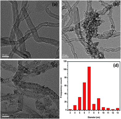 |
| | Fig. 1 TEM images of o-CNTs (a), CF-CNTs (b), CF-CNTs-A (c), and the particle size distribution of Ce–Fe mixed oxides on the surface of the CF-CNTs (d). | |
3.1.2 FT-IR spectra.
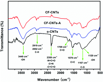
FT-IR spectra of o-CNTs, CF-CNTs and CF-CNTs-A are shown in Fig. 2. For all three samples, the peaks around 1579 cm−1, 2852 cm−1 and 2919 cm−1 can be assigned to the C![[double bond, length as m-dash]](https://www.rsc.org/images/entities/char_e001.gif) C and C–C stretching of the carbon skeleton, respectively. After oxidation by concentrated HNO3, the peaks at 1709 cm−1 and 1167 cm−1 appeared clearly in the spectra of the o-CNTs, which are associated with the asymmetric CO and C–O stretching band of the carboxylic acid (–COOH) group.36 Other stretching vibrations have been labeled in Fig. 2. The oxygen-containing groups on the surface of CNTs not only provides the CNTs with a hydrophilic nature, but also provides anchoring sites for metal oxide nanoparticles. After decoration with mixed oxides it can be found that the characteristic peak of –CO shifted from 1709 cm−1 to 1700 cm−1 and the intensity evidently decreased, indicating the double bond between the carbon and oxygen became weaker as a result of the formation of electrostatic interactions with metal ions. Thus, it is possible that the oxide nanoparticles anchored to the CNTs by an ester-like bond (Fig. 3). Differently to –CO, the relative peak intensity of the –OH vibration increased and a new peak at 1120 cm−1, which mainly belongs to the stretching vibration of –OH, appeared after oxide anchoring. Along with these functional groups, new bands occurred at 567 cm−1 on CF-CNTs and CF-CNTs-A, which may correspond to the stretching vibration between metal and oxygen (M–O–M).
C and C–C stretching of the carbon skeleton, respectively. After oxidation by concentrated HNO3, the peaks at 1709 cm−1 and 1167 cm−1 appeared clearly in the spectra of the o-CNTs, which are associated with the asymmetric CO and C–O stretching band of the carboxylic acid (–COOH) group.36 Other stretching vibrations have been labeled in Fig. 2. The oxygen-containing groups on the surface of CNTs not only provides the CNTs with a hydrophilic nature, but also provides anchoring sites for metal oxide nanoparticles. After decoration with mixed oxides it can be found that the characteristic peak of –CO shifted from 1709 cm−1 to 1700 cm−1 and the intensity evidently decreased, indicating the double bond between the carbon and oxygen became weaker as a result of the formation of electrostatic interactions with metal ions. Thus, it is possible that the oxide nanoparticles anchored to the CNTs by an ester-like bond (Fig. 3). Differently to –CO, the relative peak intensity of the –OH vibration increased and a new peak at 1120 cm−1, which mainly belongs to the stretching vibration of –OH, appeared after oxide anchoring. Along with these functional groups, new bands occurred at 567 cm−1 on CF-CNTs and CF-CNTs-A, which may correspond to the stretching vibration between metal and oxygen (M–O–M).
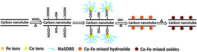 |
| | Fig. 3 Schematic representation of the preparation of CF-CNTs via a surfactant assisted method. | |
The differences in the morphologies of the particles on the surface between CF-CNTs and CF-CNTs-A is attributed to the presence or absence of NaSDBS. The role of the surfactant was to form a protective layer around the metal ions due to the electrostatic attraction between the negatively-charged hydrophilic head of the surfactant and the positively charged iron and cerium (Fig. 3). Therefore, the presence of NaSDBS inhibited the growth stage of metal oxides nanoparticles on the surface of CNTs and resulted in less aggregation and the isolation of nanoparticles.43,44 Furthermore, the addition of NaSDBS could also influence the distribution of the metal elements on the surface. The Ce distribution echoed the distribution of Fe in CF-CNTs (Fig. S5†). However, no similar phenomenon occurred in CF-CNTs-A.
3.1.3 Composition and structure analysis.
The phases and crystal nature of o-CNTs, CF-CNTs and CF-CNTs-A were investigated by X-ray diffraction (XRD) and are shown in Fig. S6.† After loading the mixed oxides, the intensity of characteristic peaks of CNTs significantly decreased, and some new peaks with quite low intensity were observed, which might be due to the oxides grafted on the surface of CNTs. Nevertheless, these new peaks suggested the nanocrystalline nature of the oxides, and no distinct principal peaks of Fe2O3 and CeO2 were observed. The chemical composition and valence state of the elements on the surface of the CNTs were further investigated by XPS and the results are shown in Fig. 4. A typical XPS survey scan of CF-CNTs is shown in Fig. 4(a). The core-level spectrum of C1s is shown in Fig. 4(b), which can be deconvoluted into two peaks at 284.6 eV and 288.9 eV corresponding with the sp2-hybridized graphite-like carbon atoms (CC) and carbon atoms in carboxylic groups (–COOH) on the surface of CF-CNTs. The peaks of Fe 2p3/2 at 711.8 eV and Fe 2p1/2 at 725.1 eV in CF-CNTs (Fig. 4(c)) correspond with the Fe 2p binding energy of FeOOH,45 demonstrating FeO(OH) was formed as the predominant phase of Fe in CF-CNTs. The Ce 3d photoelectron peaks of CF-CNTs are shown in Fig. 4(d). As reported, the Ce 3d spectrum can be assigned as two sets of spin–orbital multiplets corresponding with the 3d3/2 and 3d5/2 contributions which are labeled as u and v, respectively. Three pairs of peaks (v–u; v′′–u′′; v′′′–u′′′) arose from different Ce 4f electron configurations in the final states of the Ce(IV) species, while two couples (v°–u°; v′, u′) corresponded to the lower binding energy intensities of the 3d5/2 and 3d3/2 of the final state of the Ce(III) species.46 As shown in Fig. 4(d), the Ce 3d spectra of CF-CNTs basically denoted the presence of both Ce(III) and Ce(IV) oxidation states, resulting in a myriad of peaks and indicating the surface of the sample was not fully oxidized. The ratio of the intensity of the u′′′ peak to the total area has been frequently used to determine the surface concentration of Ce(III) in mixed oxides. It has been reported that in pure ceria the area of the u′′′ peak is 14% of the total area.47 In this study, the ratio of the u′′′ peak area is 7.62% for CF-CNTs, implying 54.35% of the total Ce on the surface exists with the oxidation state of Ce(IV), and the remaining 45.65% as Ce(III).
 |
| | Fig. 4 XPS spectra of CF-CNTs: (a) wide scan, (b) C 1s core level spectra, (c) peaks for Fe 2p and (d) peaks for Ce 3d. | |
TGA-DSC analysis was utilized for qualitative and quantitative analyses of the oxidation and decomposition behaviors of various composites. The results of weight loss and heat flow as a function of temperature for o-CNTs, CF-CNTs and CF-CNTs-A are presented in Fig. 5. The oxide loadings of CF-CNTs and CF-CNTs-A were 24.3 wt% and 29.4 wt%, respectively. The lesser loading on CF-CNTs was mainly due to partial metal ions coordinated to the anionic NaSDBS, which failed to bond with carboxyl groups on the surface of CNTs. The thermal stability of the three samples was determined by DSC curves. It was found that CNTs in the composites of CF-CNTs and CF-CNTs-A degraded at significantly lower temperatures (553 °C and 580 °C, respectively) compared with those in o-CNTs (640 °C). This shift may be ascribed to the metal oxides grafted on the sidewall of CNTs catalyzing the oxidation of CNTs, consistent with previous studies.48,49 The lower combustion point of CNTs in CF-CNTs than that in CF-CNTs-A indicated the oxides on CF-CNTs might exhibit higher catalytic activity due to their smaller particle sizes.
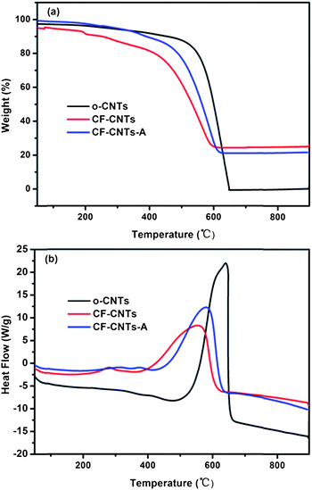 |
| | Fig. 5 TGA (a) and DSC (b) curves of o-CNTs, CF-CNTs and CF-CNTs-A. | |
3.1.4 BET and zeta potential analysis.
The BET surface areas of the pristine CNTs (p-CNTs), o-CNTs, CF-CNTs and CF-CNTs-A were 110.7 m2 g−1, 150.8 m2 g−1, 216.3 m2 g−1, and 189.0 m2 g−1, respectively. The surface area significantly increased after the acid treatment, which might be attributed to the defects on the CNTs surface as a result of acid treatment. Interestingly, the BET surface areas of the CF-CNTs and CF-CNTs-A were significantly higher than that of o-CNTs, indicating that the particles on the surface of CNTs were the main contributors to the increase of surface area, due to the micropores or mesopores introduced by the nanoparticles on the surface after the decoration of CNTs. The specific surface area of the CF-CNTs is evidently larger than that of CF-CNTs-A, suggesting the addition of NaSDBS played a very important role in the morphology of oxides on the surface of o-CNTs. The N2 adsorption/desorption isotherms and pore distribution curves are shown in Fig. S7.† All the parameters of the surface area and porosity are given in Table 1. It can be clearly found that the average pore size and macropore volume significantly decreased after decoration, which indicated the metal oxides on the surface of CNTs filled the interspace among the tubes. The zeta potentials of o-CNTs, CF-CNTs and CF-CNTs-A in a pH range of 2–10 are presented in Fig. S8.† The pHzpc values of the o-CNTs, CF-CNTs and CF-CNTs-A were 2.61, 4.68 and 4.09, respectively. After the metal oxides were loaded on the surface of CNTs, the pHzpc value evidently increased. Meanwhile, the pHzpc of CF-CNTs was higher than that of CF-CNTs-A.
Table 1 BET surface area and related data for the p-CNTs, o-CNTs, CF-CNTs and CF-CNTs-A
| Sample |
BET area, m2 g−1 |
Pore volume, cm3 g−1 |
Average pore size, nm |
Macropore, cm3 g−1 |
Mesopore, cm3 g−1 |
Micropore, cm3 g−1 |
| p-CNTs |
110.7 |
1.27 |
33.40 |
0.51 |
0.71 |
0.047 |
| o-CNTs |
150.8 |
1.25 |
32.24 |
0.53 |
0.72 |
0.061 |
| CF-CNTs |
216.3 |
1.17 |
2.81 |
0.26 |
0.69 |
0.090 |
| CF-CNTs-A |
189.0 |
1.02 |
2.01 |
0.34 |
0.70 |
0.079 |
To evaluate the adsorption capacity of the CF-CNTs and CF-CNTs-A for As(V) and As(III) the equilibrium data was fitted by Langmuir and Freundlich models. Langmuir50 and Freundlich51 adsorption models can be represented in a linear way as follows:| |  | (1) |
| |  | (2) |
where qe (mg g−1) is the equilibrium adsorption capacity of the adsorbents and Ce (mg L−1) is the equilibrium concentration of the adsorbate, qm (mg g−1) and b are the saturated adsorption capacity and the equilibrium sorption constant, respectively, and KF and n are both Freundlich constants corresponding to the adsorption capacity and adsorption intensity, respectively.
The amounts of adsorbed arsenic versus the corresponding aqueous-phase equilibrium concentration are plotted as adsorption isotherms in Fig. 6. It was found that negligible arsenic was adsorbed by the carboxylated CNT (Fig. S9†). However, CF-CNTs and CF-CNTs-A were efficient in arsenic removal. The calculated isotherm parameters of the CF-CNTs and CF-CNTs-A are summarized in Table 2. By comparison of the regression coefficients (R2), it was found that the adsorption behavior of As(V) on CF-CNTs and CF-CNTs-A could be better described by the Freundlich model, while As(III) adsorption was better fitted by the Langmuir model.
 |
| | Fig. 6 Adsorption isotherms of As(V) (a) and As(III) (b) on CF-CNTs at 298 K. The initial concentration ranged from 1 to 20 mg L−1, the dosage of adsorbents was 0.2 g L−1, and the initial pH values for the solutions were 4 and 7.5 for As(V) and As(III), respectively. | |
Table 2 Langmuir and Freundlich isotherm parameters for As(V) and As(III) adsorption on CF-CNTs and CF-CNTs-A. (Dosage = 0.2 g L−1, V = 50 mL, T = 298.15 K)
| Arsenic species |
Adsorbents |
Langmuir isotherm |
Freundlich isotherm |
|
q
m, mg g−1 |
b, L g−1 |
R
2
|
K
F, (mg g−1)(dm3 mg−1)−1/n |
n
|
R
2
|
| As(V) |
CF-CNTs |
30.96 |
2.56 |
0.9904 |
18.06 |
3.94 |
0.9969 |
| CF-CNTs-A |
16.84 |
0.63 |
0.9844 |
5.85 |
2.38 |
0.9942 |
| As(III) |
CF-CNTs |
28.74 |
1.14 |
0.9920 |
11.93 |
2.34 |
0.9860 |
| CF-CNTs-A |
16.21 |
0.89 |
0.9946 |
6.33 |
2.46 |
0.9741 |
This difference in sorption behavior may be associated with the species distribution under the experimental pH conditions. The adsorbent carried a positive charge at pH = 4 according to the pHzpc values, and As(V) existed in the anionic state of H2AsO4−. In the situation of As(III) adsorption, the adsorbent showed a state with a negative charge at pH = 7.5, but As(III) mainly existed as the molecular form of H3AsO3. We therefore postulate that it is the As(V) being adsorbed on the adsorbents by multiple mechanisms, including electrostatic attraction and surface complexation, that causes the occurrence of multilayer sorption, while As(III) was mainly adsorbed by complexation with the surface groups of the adsorbents resulting in a monolayer adsorption. From the calculated results, it can be found that the adsorption capacities of the CF-CNTs for both As(V) and As(III) were significantly higher than those of CF-CNTs-A, which might be due to the smaller and more dispersed particles on the surface of the CF-CNTs. The maximum adsorption capacity of the CF-CNTs for As(V) was 30.96 mg g−1 which was slightly higher than that for As(III) (28.74 mg g−1). When the adsorption capacity of the CF-CNTs was converted into the capacity of unit mass Ce–Fe mixed oxide (qm,Ce–Fe, mg g−1Ce–Fe), the calculated qm,Ce–Fe for As(V) and As(III) were 127.41 mg g−1Ce–Fe and 118.27 mg g−1Ce–Fe, respectively. The values are significantly higher than those of conventional Ce–Fe mixed oxide particles (68.96 mg g−1 for As(V) and 75.76 mg g−1 for As(III)).52 The adsorption capacity evaluated by the unit mass of Ce–Fe mixed oxide increased by 84.74% for As(V) and 56.11% for As(III), respectively.
The Freundlich constant KF, is defined as an adsorption or distribution coefficient which describes the amount of arsenic adsorbed on the adsorbents for the unit equilibrium concentration. The KF values of the CF-CNTs were 18.06 and 11.93, respectively. This indicated that CF-CNTs showed a higher adsorption capacity for both As(V) and As(III) than CF-CNTs-A. The other constant n in the Freundlich model for both CF-CNTs and CF-CNTs-A was found to be greater than 1, indicating the adsorbents are favorable for arsenic removal. To evaluate the performance of CF-CNTs for arsenic removal, the qm of the CF-CNTs was compared to other reported adsorbents with similar components or structures (Table 3). Although a direct comparison between the CF-CNTs with those obtained in the literature was difficult due to varying experimental conditions applied in those studies, the CF-CNTs in this work showed a higher adsorption capacity than several previous metal oxide loaded CNTs materials, such as iron, zirconium oxides loaded carbon nanotubes or Fe-grown carbon fiber. Compared with the ceria oxide loaded CNTs, the adsorption capacity of CF-CNTs was lower but the material is more economical since ferric oxide is cheaper. The comparison suggested that the CF-CNTs material has the potential to be used as an adsorbent for the decontamination of arsenic polluted water.
Table 3 Comparison of the adsorption capacity of arsenic on CF-CNTs with other reported adsorbents
| Adsorbents |
pH |
Equilibrium concentration (mg L−1) |
Adsorption capacity (mg g−1) |
References |
| As(V) |
As(III) |
As(V) |
As(III) |
As(V) |
As(III) |
| CF-CNTs |
4 |
7.5 |
0∼10.52 |
0.021∼10.17 |
30.96 |
28.74 |
This work |
| Fe-CNTs |
4 |
4 |
0.05∼13.5 |
0∼11.5 |
0.097 |
0.104 |
36
|
| Fe-modified-MCNTs |
— |
8 |
— |
0.03∼9 |
— |
4.00 |
53
|
| CNT-ZrO2 |
6 |
6 |
0∼0.0025 |
0∼0.0156 |
5.00 |
2.00 |
38
|
| CeO2-CNT |
3.1 |
— |
0∼120 |
— |
65.0 |
— |
39
|
| Fe-CNFs |
6.5 |
— |
1.0∼50 |
— |
27.7 |
— |
21
|
| MI/CNTs |
5.5 |
8 |
0.24∼9.20 |
0.30∼9.24 |
9.74 |
8.13 |
54
|
The amount of removal of arsenic by the CF-CNTs as a function of time is presented in Fig. 7. The process was time dependent, and the sorption was rapid in the first 100 min for both As(V) and As(III), and thereafter it proceeded at a relatively slower rate and finally reached equilibrium after 6 h and 5 h for As(V) and As(III), respectively.
 |
| | Fig. 7 Adsorption of As(V) and As(III) on CF-CNTs as a function of time and pseudo-second-order curves. The initial arsenic concentration was 5 mg L−1,the dosage of adsorbents was 0.2 g L−1, and the initial pH of the solution was 4 and 7.5 for As(V) and As(III), respectively. | |
The initial rapid adsorption may be due to the large number of available sites in the initial stage. As time proceeds, the concentration gradients gradually reduce due to the accumulation of arsenic adsorbed on the surface sites of CF-CNTs, leading to the decrease in the adsorption rate of the later stage.55 A little more time was required for As(V) to reach equilibrium than As(III), which may be attributed to the afore-mentioned multiple adsorption mechanism of CF-CNTs for As(V). In order to further understand the characteristics of the adsorption process, the pseudo-first-order56 and pseudo-second-order kinetic models57 were applied to fit the experimental data obtained from batch experiments. The models can be expressed as follows:
| |  | (3) |
| |  | (4) |
where
k1 (min
−1) and
k2 (g mg
−1 min
−1) are the pseudo-first order and pseudo-second order
adsorption rate constants, respectively,
qe (mg g
−1) and
qt (mg g
−1) are the sorption capacities at equilibrium and any time
t, respectively. The kinetic parameters estimated by nonlinear regression are represented in
Table 4. It is evident from the estimated correlation coefficient (
R2) that the equilibrium data was described better by the pseudo-second order model for both As(
V) and As(
III). The
adsorption rate constant
k2 of CF-CNTs for As(
III) was greater than that of As(
V), indicating a higher rate for As(
III) removal which agrees well with the experimental data. Moreover, the
q values (
qe,cal) calculated from pseudo-second order model were more consistent with the experimental
q values than those calculated from the pseudo-first order model.
Table 4 The estimated kinetic parameters for As(V) and As(III) adsorption on the CF-CNTs (pH = 4, Dosage = 0.1 g L−1, V = 50 mL, T = 298 K)
| Arsenic species |
q
e,exp
|
Pseudo-first order |
Pseudo-second order |
|
k
1, min−1 |
q
e,cal, mg g−1 |
R
2
|
k
2, g mg−1 min−1 |
q
e,cal, mg g−1 |
R
2
|
|
q
e,exp
|
| As(V) |
20.49 |
1.45 × 10⁻² |
24.55 |
0.9667 |
1.76 × 10⁻³ |
23.81 |
0.9978 |
| As(III) |
16.80 |
1.50 × 10⁻² |
22.85 |
0.9619 |
5.30 × 10⁻⁴ |
20.41 |
0.9956 |
The overall adsorption process may be controlled by either one or more steps, including outer diffusion, intra-particle diffusion and adsorption of the adsorbates onto active sites.58 The last step was considered to be rapid and thus cannot be treated as the rate-limiting step in the adsorption process.42 Consequently, the adsorption rate might be controlled by outer diffusion, inner diffusion or both. Since the general kinetics analysis could not identify the rate-limiting step of the As(V) or As(III) adsorption process on the CF-CNTs, an intra-particle diffusion model was used for the analysis of the rate-limiting step of the adsorption. The equation given by Weber and Morris can be written as:59
| |  | (5) |
where
C is the intercept (mg g
−1) and
ki is the intra-particle diffusion rate constant (mg g
−1 min
−0.5) of the adsorption step
i, which is estimated from the straight line of
qtversus t½. According to the model, if intra-particle diffusion is the rate-limiting step of the entire adsorption process, the plots of
qtversus t½ yield a straight line passing through the origin. Otherwise, some other mechanisms are possibly involved along with intra-particle diffusion. However, if the data presents multi-linear plots, then two or more steps influence the adsorption process, such as external diffusion, intra-particle diffusion,
etc.
Plots of qtversus t½ for both As(V) and As(III) are shown in Fig. 8 and the values of ki and C calculated from the slope and intercept are summarized in Table 5.
 |
| | Fig. 8 Intra-particle diffusion model for As(V) and As(III) adsorption onto CF-CNTs. The initial arsenic concentration was 5 mg L−1, the dosage of adsorbents was 0.2 g L−1, and the initial pH values of the As(V) and As(III) solution were 4 and 7.5, respectively. | |
Table 5 Intraparticle diffusion model parameters for the adsorption of As(V) and As(III) on CF-CNTs
| Arsenic species |
C
0, mg L−1 |
k
i,1, mg g−1 min−0.5 |
C
1
|
R
2
|
k
i,2, mg g−1 min−0.5 |
C
2
|
R
2
|
| As(V) |
5 |
1.226 |
0.0996 |
0.9753 |
0.0500 |
19.38 |
0.8679 |
| As(III) |
5 |
1.048 |
−0.9656 |
0.9908 |
0.0388 |
15.93 |
0.8921 |
As observed in Fig. 8, both plots present multi-linearity and were related by two straight lines. This indicated that two steps existed in the entire adsorption process: (i) the initial steep portion was a faster arsenic uptake attributed to the diffusion of adsorbate through the solution to the external surface of the adsorbent (external diffusion), (ii) the gradual adsorption stage, corresponding to diffusion of the adsorbate species inside the pores of the adsorbent (intra-particle diffusion). Therefore, intra-particle diffusion was involved in the process of both As(V) and As(III) adsorption on CF-CNTs, but was not the only rate-limiting step.
3.4 The effect of solution pH on arsenic adsorption on CF-CNTs
Solution pH can affect both the zeta potential of the adsorbents and arsenic species. The removal efficiency of arsenic by CF-CNTs as a function of a broad pH range is represented in Fig. 9. It was found that the pH had a pronounced effect on the arsenic uptake on CF-CNTs. The removal of As(V) increased clearly under relatively strong acidic conditions of pH = 2–3. It is known that As(V) exists predominantly as the molecular state of H3AsO4 below pH = 2.3.60 A higher pH can promote the ionization of H3AsO4, resulting in the enhancement of the electrostatic attraction between negative As(V) ions and positively-charged CF-CNTs. The deprotonation of surface hydroxyl groups occurred with further increasing pH, resulting in a negatively-charged surface. This unfavorable condition for As(V) adsorption would be exacerbated at a alkaline pH range due to the competition of OH− with arsenate. However, the adsorption of As(III) on CF-CNTs was different. The optimum pH range for As(III) adsorption was found to be at 7–9. At a pH below 7, the removal efficiency significantly increased with the increment of pH, but the As(III) uptake was lower at a pH range of 9–10. The species of As(III) existed mainly as H3AsO3 and H2AsO3− when the pH was below 9.2,60 indicating As(III) was adsorbed on CF-CNTs by the surface complexation mechanism. The adsorption capacity increment with the pH increasing might be attributed to more surface hydroxyl groups on CF-CNTs at higher pH values. The removal efficiency dropped at pH values above 9 due to the ionization of H3AsO3, which resulted in the occurrence of more competition between arsenite and OH− anions. The increasing Coulombic repulsion between As(III) species and the negative surfaces of CF-CNTs was the main reason. A discovery in this study was that little Fe or Ce leached into the solution, even under the acidic conditions of pH = 2, indicating the CF-CNTs were stable and might be used in a broad pH range.
 |
| | Fig. 9 Effect of pH on arsenic adsorption by CF-CNTs at 298 K. The initial arsenic concentration was 5 mg L−1 and the dosage of adsorbents was 0.2 g L−1. | |
 |
| | Fig. 10 As 3d core levels of CF-CNTs after the adsorption of As(V) (a) and As(III) (b). | |
Commonly, the binding energies of the As 3d core level for As(III) and As(V) in arsenic oxides are 44.3–44.5 and 45.2–45.6 eV, respectively.61,62 The result indicated that both As(III) and As(V) species existed on the surface of CF-CNTs after the adsorption of As(III). Thus, the presence of As(V) indicated that the oxidation of part of As(III) to As(V) occurred during the adsorption process, which might be related to the oxidizing ability of Ce(IV) and possibly dissolved oxygen in the solution. The As(V) accounted for 60.78% of the total arsenic adsorbed by CF-CNTs. The surface compositions of the typical samples are presented in Table 6.
Table 6 Surface composition of CF-CNTs before and after arsenic adsorption
| Samples |
C (at%) |
Fe (at%) |
Ce (at%) |
O (at%) |
As (at%) |
| CF-CNTs |
60.62 |
6.89 |
1.15 |
31.34 |
0 |
| As(V)-saturated CF-CNTs |
56.16 |
5.52 |
1.02 |
35.85 |
1.44 |
| As(III)-saturated CF-CNTs |
58.26 |
5.71 |
0.98 |
33.73 |
1.31 |
Both the Fe and Ce content decreased a little after the adsorption of As(V) or As(III), while the O and As element content increased due to the introduction of H2AsO4− and H3AsO3. The XPS spectra of Fe 2p before and after arsenic adsorption are illustrated in Fig. 11(a). The position of the Fe 2p peak did not shift implying the valence state of Fe did not change after the adsorption of arsenic. The spectra intensity of Fe 2p slightly decreased after the adsorption of As(V) or As(III), indicating the interaction occurred between the Fe atom and the surface arsenic species. It was observed that the Ce 3d spectra intensity of the CF-CNTs decreased a little after the adsorption of arsenic, suggesting the interaction also occurred between the Ce atom and arsenic species (Fig. 11(b)). The fitting data and peak shapes demonstrated that no obvious change of the intensity of u′′′ peak was observed, indicating the valence state distribution of Ce did not change during the reaction with As(V). However, the intensity of u′′′ decreased evidently by 13.05% after reaction with As(III), suggesting that part of Ce(IV) was reduced to Ce(III). The Ce(IV) and Ce(III) contents of the total Ce atom before and after arsenic adsorption are presented in Table 7.
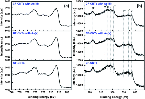 |
| | Fig. 11 Fe 2p (a) and Ce 3d (b) spectra of CF-CNTs before and after arsenic adsorption. | |
Table 7 Summary of u′′′ percentages for CF-CNTs before and after arsenic adsorption
| Samples |
Binding energy, eV |
u′′′ area, % |
Ce(III), % |
Ce(IV), % |
| Pure CeO2 (ref. 52) |
917.1 |
14.02 |
0 |
100 |
| CF-CNTs |
917.4 |
7.62 |
45.65 |
54.35 |
| As(V)-saturated CF-CNTs |
917.2 |
7.73 |
44.87 |
55.13 |
| As(III)-saturated CF-CNTs |
917.3 |
5.79 |
58.70 |
41.30 |
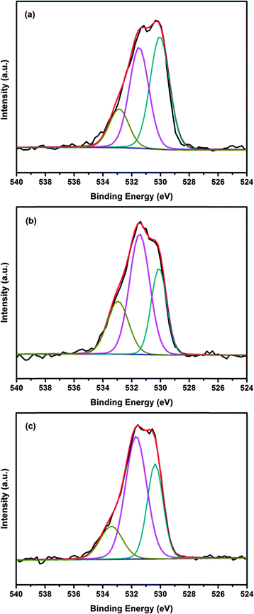
The O1s spectra of the CF-CNTs before and after the adsorption of arsenic are shown in Fig. 12. The binding energies of O1s and their variations on the surface are summarized in Table 8. It has been reported that hydroxyl groups on the surface of adsorbents played an important role in arsenic adsorption.63–65 The area ratio for the peak located at 531.5 eV, which can be assigned to hydroxyl bond to the metal oxide (M–OH), obviously increased from 40.57% to 52.97% and 54.13%, respectively, after reaction with As(V) and As(III). This is possibly due to the formation of highly hydroxylated arsenate surface complexes via the reaction between M–OH and As–OH. There are three possible arsenate surface complexes resulting from the ligand exchange reaction, including binuclear, bidentate, and monodentate complexes.66 The stoichiometric ratios of surface hydroxyl between the original adsorbents and arsenate-saturated adsorbents were1![[thin space (1/6-em)]](https://www.rsc.org/images/entities/char_2009.gif) :2 for a monodentate surface complex, and 2:1 for a bidentate one.63,67Table 8 shows the ratios between the surface hydroxyl of CF-CNTs and As-saturated CF-CNTs were 1:1.31 and 1.33 after As(V) and As(III) adsorption, respectively, which was between ½ and 2, suggesting only monodentate complexes existed with original –OH groups, or the monodentate and bidentate complexes coexist on the surface of CF-CNTs. However, many reported EXAFS studies revealed that the dominant species of As(V) existing on iron oxides, as well as iron oxyhydroxide, have been proven as bidentate complexes.9,63,68–70 Thus, both monodentate and bidentate complexes may form during the adsorption of arsenic on the surface of CF-CNTs.
:2 for a monodentate surface complex, and 2:1 for a bidentate one.63,67Table 8 shows the ratios between the surface hydroxyl of CF-CNTs and As-saturated CF-CNTs were 1:1.31 and 1.33 after As(V) and As(III) adsorption, respectively, which was between ½ and 2, suggesting only monodentate complexes existed with original –OH groups, or the monodentate and bidentate complexes coexist on the surface of CF-CNTs. However, many reported EXAFS studies revealed that the dominant species of As(V) existing on iron oxides, as well as iron oxyhydroxide, have been proven as bidentate complexes.9,63,68–70 Thus, both monodentate and bidentate complexes may form during the adsorption of arsenic on the surface of CF-CNTs.
 |
| | Fig. 12 O 1s spectra with three deconvolutions of CF-CNTs (a), As(V) saturated (b) and As(III)-saturated (c) CF-CNTs. | |
Table 8 Relative contents of O 1s in various chemical states
| Binding energy, eV |
Chemical states |
CF-CNTs (%) |
As(V)-saturated CF-CNTs (%) |
As(III)-saturated CF-CNTs (%) |
| 530.2 ± 0.2 |
Metal oxides |
42.00 |
28.33 |
29.23 |
| 531.6 ± 0.1 |
OH− |
40.57 |
52.97 |
54.13 |
| 533.1 ± 0.2 |
O–CO, C–OH |
17.43 |
17.70 |
16.64 |
Therefore, the surface hydroxyl on the CF-CNTs slightly increased after reaction with arsenate, which was likely due to the formation of more bidentate complexes by ferric ions and arsenate, and a small amount of monodentate complexes by Ce ions and arsenate. Different to arsenate adsorption, some arsenite species that were not oxidized to arsenate in the experimental conditions were adsorbed on the CF-CNTs material only via the formation of monodentate complexes.71
Based on the above analysis, the adsorption of As(V) on the CF-CNTs under the experimental conditions showed a complex mechanism, including electrostatic attraction and surface complexation, and including both monodentate and bidentate complexation. For As(III), a part of As(III) was oxidized to As(V) by the Ce(IV) of CF-CNTs and then adsorbed on the adsorbents, while the rest of the As(III) directly adsorbed on the Ce–Fe mixed oxide surface of CF-CNTs. Possibly the main mechanism of As(III) adsorption was through the surface complexation to form monodentate complexes. The proposed mechanism for arsenic adsorption by CF-CNTs is demonstrated in Fig. 13.
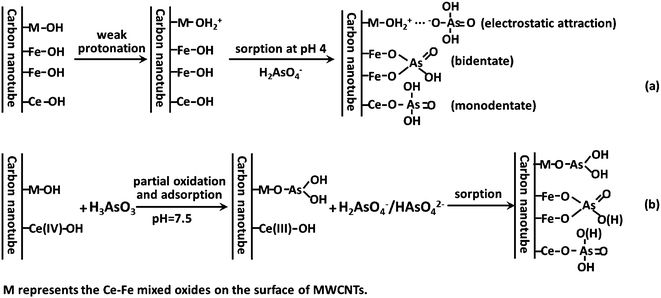 |
| | Fig. 13 Schematic diagram for the proposed mechanism of As(V) (a) and As(III) (b) adsorption on CF-CNTs. | |
4 Conclusions
A novel Ce–Fe mixed oxide decorated multiwalled carbon nanotubes (CF-CNTs) material was successfully prepared through a surfactant-assisted method. This CF-CNTs material was used as an adsorbent to remove arsenic from aqueous solutions and showed good adsorption efficiency for As(V) and As(III). The adsorption behaviour of As(V) and As(III) can be excellently described by the Freundlich and Langmuir models, respectively, and the kinetics were explained by a pseudo-second-order model. The experimental results demonstrated that the As(V) adsorption was through a complex mechanism including electrostatic attraction and the replacement of OH groups to form monodentate and bidentate complexes. For the As(III) adsorption process, partial As(III) species were oxidized to As(V), followed by simultaneous adsorption of As(V), while the rest of the As(III) was directly adsorbed on the Ce–Fe mixed oxide of CF-CNTs mainly through the formation of monodentate complexes. It is concluded that the CF-CNTs material obtained in this work is a potential efficient adsorbent for the decontamination of arsenic-polluted water. But for practical applications, more studies such as economic evaluation, continuous flow adsorption and field experiments are still needed.
Acknowledgements
This work was supported by the National Natural Science Foundation of China (no. 41072173, 21177095, 21207100), Program for New Century Excellent Talents in University (NCET-10-0597), State Key Laboratory of Pollution Control and Resource Reuse Foundation (no. PCRRK09006, PCRRY11009), and Shanghai Pujiang Program (10PJ1410200)
References
- B. K. Mandal and K. T. Suzuki, Talanta, 2002, 58, 201–235 CrossRef CAS.
- C.-J. Chen, S.-L. Wang, J.-M. Chiou, C.-H. Tseng, H.-Y. Chiou, Y.-M. Hsueh, S.-Y. Chen, M.-M. Wu and M.-S. Lai, Toxicol. Appl. Pharmacol., 2007, 222, 298–304 CrossRef CAS.
- J. Bundschuh, M. I. Litter, F. Parvez, G. Roman-Ross, H. B. Nicolli, J. S. Jean, C. W. Liu, D. Lopez, M. A. Armienta, L. R. G. Guilherme, A. G. Cuevas, L. Cornejo, L. Cumbal and R. Toujaguez, Sci. Total Environ., 2012, 429, 2–35 CrossRef CAS.
- T. S. Y. Choong, T. G. Chuah, Y. Robiah, F. L. Gregory Koay and I. Azni, Desalination, 2007, 217, 139–166 CrossRef CAS.
- T. Yoshida, Toxicol. Appl. Pharmacol., 2004, 198, 243–252 CrossRef CAS.
- P. L. Smedley and D. G. Kinniburgh, Appl. Geochem., 2002, 17, 517–568 CrossRef CAS.
- D. Mohan and C. U. Pittman, J. Hazard. Mater., 2007, 142, 1–53 CrossRef CAS.
- M. L. Farquhar, J. M. Charnock, F. R. Livens and D. J. Vaughan, Environ. Sci. Technol., 2002, 36, 1757–1762 CrossRef CAS.
- B. C. Bostick and S. Fendorf, Geochim. Cosmochim. Acta, 2003, 67, 909–921 CrossRef CAS.
- J. Gimenez, M. Martinez, J. Depablo, M. Rovira and L. Duro, J. Hazard. Mater., 2007, 141, 575–580 CrossRef CAS.
- K. Banerjee, G. L. Amy, M. Prevost, S. Nour, M. Jekel, P. M. Gallagher and C. D. Blumenschein, Water Res., 2008, 42, 3371–3378 CrossRef CAS.
- B. Wang, H. Wu, L. Yu, R. Xu, T.-T. Lim and X. W. D. Lou, Adv. Mater., 2012, 24, 1111–1116 CrossRef CAS.
- S. J. Zhang, X. Y. Li and J. P. Chen, Carbon, 2010, 48, 60–67 CrossRef CAS.
- K. Gupta, T. Basu and U. C. Ghosh, J. Chem. Eng. Data, 2009, 54, 2222–2228 CrossRef CAS.
- K. Gupta, S. Saha and U. C. Ghosh, J. Nanopart. Res., 2008, 10, 1361–1368 CrossRef CAS.
- Y. Zhang, X. M. Dou, M. Yang, H. He, C. Y. Jing and Z. Y. Wu, J. Hazard. Mater., 2010, 179, 208–214 CrossRef CAS.
- S. X. Zhang, H. Y. Niu, Y. Q. Cai, X. L. Zhao and Y. L. Shi, Chem. Eng. J., 2010, 158, 599–607 CrossRef CAS.
- G. Zhang, J. Qu, H. Liu, R. Liu and R. Wu, Water Res., 2007, 41, 1921–1928 CrossRef CAS.
- M. Jang, W. F. Chen and F. S. Cannon, Environ. Sci. Technol., 2008, 42, 3369–3374 CrossRef CAS.
- A. K. Mishra and S. Ramaprabhu, J. Phys. Chem. C, 2010, 114, 2583–2590 CAS.
- A. K. Gupta, D. Deva, A. Sharma and N. Verma, Ind. Eng. Chem. Res., 2010, 49, 7074–7084 CrossRef CAS.
- V. Chandra, J. Park, Y. Chun, J. W. Lee, I. C. Hwang and K. S. Kim, ACS Nano, 2010, 4, 3979–3986 CrossRef CAS.
- X. L. Wu, L. Wang, C. L. Chen, A. W. Xu and X. K. Wang, J. Mater. Chem., 2011, 21, 17353–17359 RSC.
- Z. Wu, W. Li, P. A. Webley and D. Zhao, Adv. Mater., 2012, 24, 485–491 CrossRef CAS.
- S. Iijima, Nature, 1991, 354, 56–58 CrossRef CAS.
- M. S. Dresselhaus and I. L. Thomas, Nature, 2001, 414, 332–337 CrossRef CAS.
- W. Y. Lu, N. Li, S. Y. Bao, W. X. Chen and Y. Y. Yao, Carbon, 2011, 49, 1699–1709 CrossRef CAS.
- S. Zhang, C. Y. Ji, Z. Q. Bian, P. R. Yu, L. H. Zhang, D. Y. Liu, E. Z. Shi, Y. Y. Shang, H. T. Peng, Q. Cheng, D. Wang, C. H. Huang and A. Y. Cao, ACS Nano, 2012, 6, 7191–7198 CrossRef CAS.
- D. Vidick, M. Herlitschke, C. Poleunis, A. Delcorte, R. P. Hermann, M. Devillersa and S. Hermans, J. Mater. Chem. A, 2013, 1, 2050–2063 CAS.
- L. Ai, C. Zhang, F. Liao, Y. Wang, M. Li, L. Meng and J. Jiang, J. Hazard. Mater., 2011, 198, 282–290 CrossRef CAS.
- G. C. Chen, X. Q. Shan, Y. S. Wang, Z. G. Pei, X. E. Shen, B. Wen and G. Owens, Environ. Sci. Technol., 2008, 42, 8297–8302 CrossRef CAS.
- F. Yu, J. Ma and Y. Wu, J. Hazard. Mater., 2011, 192, 1370–1379 CrossRef CAS.
- M. Kah, X. Zhang, M. T. O. Jonker and T. Hofmann, Environ. Sci. Technol., 2011, 45, 6011–6017 CrossRef CAS.
- J. Wang, X. Ma, G. Fang, M. Pan, X. Ye and S. Wang, J. Hazard. Mater., 2011, 186, 1985–1992 CrossRef CAS.
- M. A. Tofighy and T. Mohammadi, J. Hazard. Mater., 2011, 185, 140–147 CrossRef CAS.
- S. A. Ntim and S. Mitra, J. Chem. Eng. Data, 2011, 56, 2077–2083 CrossRef.
- T. A. Saleh, S. Agarwal and V. K. Gupta, Appl. Catal., B, 2011, 106, 46–53 CAS.
- S. A. Ntim and S. Mitra, J. Colloid Interface Sci., 2012, 375, 154–159 CrossRef.
- X. Peng, Z. Luan, J. Ding, Z. Di, Y. Li and B. Tian, Mater. Lett., 2005, 59, 399–403 CrossRef CAS.
- J. Ma, J. N. Wang and X. X. Wang, J. Mater. Chem., 2009, 19, 3033 RSC.
- J. Ma and J. N. Wang, Chem. Mater., 2008, 20, 2895–2902 CrossRef CAS.
- F. Yu, J. Chen, L. Chen, J. Huai, W. Gong, Z. Yuan, J. Wang and J. Ma, J. Colloid Interface Sci., 2012, 378, 175–183 CrossRef CAS.
- I. T. Kim, G. A. Nunnery, K. Jacob, J. Schwartz, X. T. Liu and R. Tannenbaum, J. Phys. Chem. C, 2010, 114, 6944–6951 CAS.
- O. Matarredona, H. Rhoads, Z. R. Li, J. H. Harwell, L. Balzano and D. E. Resasco, J. Phys. Chem. B, 2003, 107, 13357–13367 CrossRef CAS.
- J. G. Radich, R. Dwyer and P. V. Kamat, J. Phys. Chem. Lett., 2011, 2, 2453–2460 CrossRef CAS.
- Z.-Q. Zhao, X. Chen, Q. Yang, J.-H. Liu and X.-J. Huang, Chem. Commun., 2012, 48, 2180 RSC.
- J. He, G. K. Reddy, S. W. Thiel, P. G. Smirniotis and N. G. Pinto, J. Phys. Chem. C, 2011, 115, 24300–24309 CAS.
- B. Gao, C. Peng, G. Z. Chen and G. L. Puma, Appl. Catal., B, 2008, 85, 17–23 CrossRef CAS.
- R. Brukh and S. Mitra, J. Mater. Chem., 2007, 17, 619–623 RSC.
- I. Langmuir, J. Am. Chem. Soc., 1916, 1, 2221–2295 CrossRef.
- H. M. F. Freundlich, J. Phys. Chem., 1906, 57, 385–471 CAS.
- B. Chen, Z. Zhu, Y. Guo, Y. Qiu and J. Zhao, J. Colloid Interface Sci., 2013, 398, 142–151 CrossRef CAS.
- B. Tawabini, S. Al-Khaldi, M. Khaled and M. Atieh, J. Environ. Sci. Health, Part A: Toxic/Hazard. Subst. Environ. Eng., 2011, 46, 215–223 CrossRef CAS.
- J. Ma, Z. Zhu, B. Chen, M. Yang, H. Zhou, C. Li, F. Yu and J. Chen, J. Mater. Chem. A, 2013, 1, 4662 CAS.
- J. Hu, D. Shao, C. Chen, G. Sheng, X. Ren and X. Wang, J. Hazard. Mater., 2011, 185, 463–471 CrossRef CAS.
-
S. Lagergren, Kungliga Sevenska VetenskapsakademiensHandlingar, 1898, vol. 24, pp. 1–39 Search PubMed.
- G. M. Y. S. Ho, Process Biochem., 1999, 34, 451–465 CrossRef.
- S. Rengaraj, Y. Kim, C. K. Joo and J. Yi, J. Colloid Interface Sci., 2004, 273, 14–21 CrossRef CAS.
-
J. C. M. W. J. Weber, Adsorption Processes for Water Treatment, Buterworth, London, 1987 Search PubMed.
- N. B. Issa, V. N. Rajakovic-Ognjanovic, B. M. Jovanovic and L. V. Rajakovic, Anal. Chim. Acta, 2010, 673, 185–193 CrossRef.
- D. Fullston, D. Fornasiero and J. Ralston, Langmuir, 1999, 15, 4530–4536 CrossRef CAS.
- S. Ouvrard, P. de Donato, M. O. Simonnot, S. Begin, J. Ghanbaja, M. Alnot, Y. B. Duval, F. Lhote, O. Barres and M. Sardin, Geochim. Cosmochim. Acta, 2005, 69, 2715–2724 CrossRef CAS.
- Y. Zhang, M. Yang, X. M. Dou, H. He and D. S. Wang, Environ. Sci. Technol., 2005, 39, 7246–7253 CrossRef CAS.
- Z. J. Li, S. B. Deng, G. Yu, J. Huang and V. C. Lim, Chem. Eng. J., 2010, 161, 106–113 CrossRef CAS.
- Y. Ma, Y. M. Zheng and J. P. Chen, J. Colloid Interface Sci., 2011, 354, 785–792 CrossRef CAS.
- S. Fendorf, M. J. Eick, P. Grossl and D. L. Sparks, Environ. Sci. Technol., 1997, 31, 315–320 CrossRef CAS.
-
N. C. Brady and R. R. Weil, The nature and properties of soils, Prentice-Hall Inc., 1996 Search PubMed.
- G. Morin, G. Ona-Nguema, Y. Wang, N. Menguy, F. Juillot, O. Proux, F. Guyot, G. Calas and G. E. Brown Jr, Environ. Sci. Technol., 2008, 42, 2361–2366 CrossRef CAS.
- M. Stachowicz, T. Hiemstra and W. H. van Riemsdijk, J. Colloid Interface Sci., 2006, 302, 62–75 CrossRef CAS.
- Y. Wang, G. Morin, G. Ona-Nguema, F. Juillot, F. Guyot, G. Calas and G. E. Brown Jr, Environ. Sci. Technol., 2009, 44, 109–115 CrossRef.
- Z. M. Ren, G. S. Zhang and J. P. Chen, J. Colloid Interface Sci., 2011, 358, 230–237 CrossRef CAS.
Footnote |
| † Electronic supplementary information (ESI) available. See DOI: 10.1039/c3ta11827d |
|
| This journal is © The Royal Society of Chemistry 2013 |
Click here to see how this site uses Cookies. View our privacy policy here.  Open Access Article
 This Open Access Article is licensed under a Creative Commons Attribution-Non Commercial 3.0 Unported Licence