 Open Access Article
 This Open Access Article is licensed under a
 Creative Commons Attribution 3.0 Unported Licence
Atomic layer deposition of platinum clusters on titania nanoparticles at atmospheric pressure
Aristeidis
Goulas
and
J.
Ruud van Ommen
*
Delft University of Technology, Department of Chemical Engineering, 2628 BL Delft, The Netherlands. E-mail: j.r.vanommen@tudelft.nl
First published on 21st February 2013
Abstract
We report the fabrication of platinum nanoclusters with a narrow size distribution on TiO2 nanoparticles using atomic layer deposition. With MeCpPtMe3 and ozone as reactants, the deposition can be carried out at a relatively low temperature of 250 °C. Our approach of working with suspended nanoparticles at atmospheric pressure gives precise control of the material properties, high efficiency of the use of the platinum precursor, and the possibility for large-scale production of the nanostructured particles.
Platinum (Pt) is widely applied to catalyse chemical reactions, despite its high price. Pt-based nanostructured catalysts are for example used in (petro)chemical and refining processes (hydro-, dehydrogenation reactions), fuel cells, automotive applications (emission control, combustion promotion) and fine chemical production (bioconversion, selective oxidation).1–5 For optimizing the catalyst performance – its activity, selectivity, and stability – while keeping the amount of scarce and expensive utilized Pt at a minimum, it is crucial to maintain excellent control over the morphology and distribution of the metal clusters during their synthesis process. Traditional Pt nanoparticle deposition techniques, such as impregnation,6,7 deposition–precipitation,7,8 and ion-exchange,9,10 rely on wet-chemistry schemes and often result in inefficient control of the active phase growth. In the past years, atomic layer deposition (ALD) has appeared as an appealing nanofabrication technique for the preparation of precisely tailored heterogeneous catalysts.11,12
In ALD, two self-limiting and complementary reactions are used in an alternating sequence to build-up solid films on a surface. Due to the finite initial number of surface sites, the reactions can only deposit a certain number of surface species.12,13 The majority of ALD research is aimed at depositing continuous films for microelectronic applications. Due to its high surface (cohesive) energy (∼2.5 J m−2) Pt deposition on oxide supports such as titania proceeds via an island growth mechanism (Volmer–Weber mechanism) during the initial stages of ALD processes.14–16 Ultimately, after a sufficient number of exposure cycles, the deposited islands will merge to form a Pt thin film. However, for applications in catalysis it is typically undesirable to obtain a continuous film: the island structure should be maintained to maximize the dispersion. Elam et al.17 and King et al.18 described the nucleation and growth of Pt on oxide support materials referring to the potential benefits for catalysis applications.
For most catalytic applications, it is crucial to deposit the catalytic material on a particulate support material. To the best of our knowledge, Lashdaf et al.19 were the first to report ALD to deposit Pt on a powder support (silica and alumina) for the fabrication of a catalyst. They used a flow-type reactor, in which an inert gas containing the precursors was flowing along the substrate at a reduced pressure. Such a flow-type reactor is the most commonly used device to carry-out ALD.20,21 Flow-type reactors are usually designed for conducting deposition on flat substrates and therefore are not optimized for use with powder support materials; they can only handle amounts up to a few grams. For real-life catalytic applications it is crucial that large amounts of Pt-containing catalysts can be synthesized while maintaining properties such as homogeneous distribution and a monodispersed size of the Pt clusters. Following the introduction of the use of a fluidized bed reactor for ALD by Wank et al.22 several efforts have been made towards the application of fluidized beds as efficient ALD reactors for powder coating applications.23,24 Recently, Weimer et al.25–27 demonstrated the use of fluidized bed reactors operated under reduced pressure to deposit Pt on micron- and nano-sized powder supports using an organometallic Pt complex and oxygen. In the fluidized-bed ALD reactor, the inert gas flow carrying the reactants travels through the collection of particles at such a velocity that they are suspended. Highly dispersed Pt islands were deposited although there was some decomposition of the precursor.26,27 A disadvantage of operating a fluidized bed at low pressure is, however, that the mixing is strongly reduced; especially when scaling-up the system this will negatively influence the product properties.28,29
In this communication we present a novel approach to deposit Pt on nanoparticles in a fluidized-bed ALD reactor at atmospheric pressure, using an ozone-containing air stream as an oxidizer medium. So far, ALD deposition of Pt has only been shown at vacuum. We will demonstrate that the precision characteristics of ALD can be maintained at atmospheric pressure, effectively proving the potential of the process for catalyst fabrication on an industrially relevant scale.
The experiments were carried out in a custom-build fluidized-bed ALD reactor operated at atmospheric pressure. The noble metal precursor, (trimethyl)methylcyclopentadienylplatinum(IV) (MeCpPtMe3, 99% purity) was obtained from Strem Chemicals and was used as received. It was contained in a heated (50 °C) steel vessel connected to the reactor. Air enriched with ozone (around 1.5 wt%) was used as an oxidizer medium; this stream was obtained by leading an air flow (0.20 L min−1) through an OAS Topzone ozone generator. We checked that the reactor feeding system did not lead to significant ozone decomposition. Aeroxide P-25 titanium dioxide particles (TiO2, ≥99.5% purity) from Evonik were used as the substrate for the deposition. They have an average primary particle diameter of 21 nm and a surface area of ∼50 m2 g−1 (determined in a Quantachrome Autosorb-6B). The crystal structure is about 85% anatase and 15% rutile. The reactor chamber consists of a vertical glass tube with an inner diameter of 10 mm, which is filled with 0.25 g of particles. At the bottom of the glass tube, a porous metal plate is placed to contain the particles, allowing an upward gas flow. An inert gas flow of dry nitrogen (N2, 99.999 vol%) is provided in the upward direction to suspend the particles. By setting the gas flow to 0.20 L min−1 (flow rate corresponding to a superficial gas velocity of 4.2 cm s−1) we ensured that the particles were well suspended (fluidized) while preventing them from being blown out from the column. The column was placed on a vibration table to ensure proper fluidization of the cohesive powder. An infrared-heater with feedback control was used to keep the reactor at the desired reaction temperature of 250 °C. A more elaborate description of a similar setup is given by Beetstra et al.23 After loading the particles in the reactor, a pre-treatment procedure (heating under inert gas flow) was followed to ensure a constant initial number of OH-groups on the surface of the support. The main ALD process sequence involved alternating pulsing of the two precursors, separated by sufficient purging times of inert gas. A typical pulsing sequence for Pt–N2–O3–N2 consisted of exposure times of 3–10–10–10 min. We determined the amount of Pt deposited on the substrate by inductively coupled plasma optical emission spectrometry (ICP-OES) using a Perkin Elmer Optima 3000 DV optical emission spectrometer. The carbon content of the samples was measured by IR absorption spectroscopy using a carbon/sulphur determinator (LECO CS-225). TEM pictures of the samples were taken using a FEI Tecnai TF20 equipped with an EDX detector (Oxford Instruments). XRD measurements were carried out with a Bruker D8 Advance diffractometer.
In ALD processes, an important characteristic is the amount of material deposited as a function of the exposure time and of the number of cycles applied. During the ALD process, saturation should occur when the precursor exposure time is long enough. Because of the total surface area in our experiments (12–14 m2 per sample batch), a long precursor exposure time was required, after about 12 min saturation occurred, and a loading of 1.6 wt% was determined with ICP-OES. In this case, just ∼50% of the Pt provided via the precursor was loaded onto the substrate. However, when aiming for the growth of islands rather than a continuous film, there is no need to go to complete saturation. We found that after 3 min we already reached a deposition amount that was about half of the saturated deposition amount. Fig. 1 shows the measured wt% of Pt (□) as well as the theoretical wt% predicted for ideal ALD (x). The results show that about 95% of the precursor provided was converted into Pt clusters, which is attractive for an expensive metal such as Pt. When processing larger amounts of powder, it will be possible to reduce even further these losses. Fig. 1 also shows that increasing the number of cycles from 1 to 4, a monotonic increase in the Pt loading was observed. Additionally, the surface area (♦) showed a small increase (about 5% for 4 cycles, in agreement with previous studies on non-porous supports30) that could be justified by the growth of Pt nanoclusters. This Pt loading of the 1-cycle experiments is about 10% higher than what Zhou et al.26 obtained at 400 °C, and more than double of what they obtained at 250 °C with oxygen as the second reactant. The main reason for that is probably related to our use of ozone, which is a more powerful oxidizer than oxygen (the redox potential of O3 is 2.07 V, while for O2 it is 1.23 V).
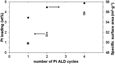 | ||
| Fig. 1 Pt loading measured by ICP (□) and predicted for ideal ALD (x) along with changes in specific surface area (♦) as a function of ALD cycles (Pt content values corrected for changes in specific surface area). | ||
It is attractive to synthesize the Pt nanoclusters at a low temperature, since this prevents their coalescence. We show in this work, that the use of ozone allows us to operate in the lower limit of the temperature window of ALD processing,31,32 achieving more uniform deposition conditions without compromising the rate of material growth. Additionally, future use of high-surface area supports is expected to be favoured by the controlled deposition nature of ALD, resulting in high-dispersion values.25,27
For catalytic applications, dispersion of the Pt nanoclusters is often of great importance. We investigated this examining several TEM images of the prepared materials. To quantify the particle size and its spread, we applied image analysis to multiple TEM images. In order to get good statistics, this was done for samples with higher Pt loadings: 12 min deposition time for 1 ALD cycle (1.6 wt%) and 5 min deposition time for 5 ALD cycles (5.8 wt%). For both loadings about 150 Pt nanoparticles were processed. Fig. 2(a) shows the TiO2 support particles after 1 ALD cycle. A uniform distribution of the active phase Pt particles can be seen. The presence of Pt was verified by qualitative EDX elemental analysis. Fig. 2(b) shows the substrate after 5 ALD cycles. The average particle size clearly increased for an increase in the Pt content from 1.6 to 5.8 wt%. The carbon content of all the samples was very low (less than 0.5 wt%) as obtained by IR absorption spectroscopy.
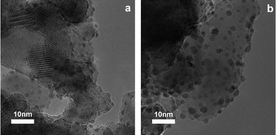 | ||
| Fig. 2 TEM image of Pt nanoclusters deposited onto the TiO2 support after 1 ALD cycle (a) and 5 ALD cycles (b). | ||
Fig. 3 gives the particle size distribution for both cases. The particle diameter after 1 cycle ALD is just 1.5 nm, with a very narrow size distribution. Increasing the Pt loading with a higher number of cycles increases the particle size to 2.3 nm, leading to a less narrow size distribution. These results further indicate that ALD is a precise fabrication technique for both low- and medium-loading noble metal catalysts.
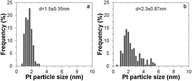 | ||
| Fig. 3 Particle size distribution from image analysis of TEM pictures for Pt nanoclusters deposited onto the TiO2 support after 1 ALD cycle (a) and after 5 ALD cycles (b). | ||
ALD-tailored nanostructured materials show very promising potential for noble metal heterogeneous catalyst applications where finely distributed ultra-dispersed particles can result in significant cost reductions: when so well dispersed, the catalytic material is used much more efficiently. Moreover, the demonstrated method is efficient in its use of platinum. The operation in atmospheric pressure conditions strongly enhances the potential for scale-up of the process: it makes the handling and mixing of the powder that serves as a substrate much easier.
Conclusions
In summary, we demonstrated that small Pt nanoclusters of controlled size can be deposited on TiO2 nanoparticles (21 nm) by ALD in a fluidized bed at atmospheric pressure, using MeCpPtMe3 and ozone as reactants. The use of ozone as an oxidizer enabled us to obtain successful ALD at a temperature as low as 250 °C. By using relatively short cycle times to avoid reaching saturation, we were able to utilize the Pt-precursor with 95% efficiency. By varying the number of ALD cycles we were able to precisely control the catalyst loading obtaining homogeneously distributed, highly dispersed Pt nanoclusters with a narrow particle size distribution. This demonstrates the potential of the approach to produce high-quality catalysts, while the operation at atmospheric pressure enables the synthesis of large amounts of material.Notes and references
- A. Chen and P. Holt-Hindle, Chem. Rev., 2010, 110, 3767–3804 CrossRef CAS.
- Z. Peng and H. Yang, Nano Today, 2009, 4, 143–164 CrossRef CAS.
- N. R. Shiju and V. V. Guliants, Appl. Catal., A, 2009, 356, 1–17 CrossRef CAS.
- S. Carrettin, P. McMorn, P. Johnston, K. Griffin, C. J. Kiely and G. J. Hutchings, Phys. Chem. Chem. Phys., 2003, 5, 1329–1336 RSC.
- M. K. Debe, Nature, 2012, 486, 43–51 CrossRef CAS.
- L. Li, Q. Shen, J. Cheng and Z. Hao, Appl. Catal., B, 2010, 93, 259–266 CrossRef CAS.
- G. R. Bamwenda, S. Tsubota, T. Nakamura and M. Haruta, J. Photochem. Photobiol., A, 1995, 89, 177–189 CrossRef CAS.
- A. J. Plomp, H. Vuori, A. O. I. Krause, K. P. de Jong and J. H. Bitter, Appl. Catal., A, 2008, 351, 9–15 CrossRef CAS.
- P. Claus, S. Schimpf, R. Schödel, P. Kraak, W. Mörke and D. Hönicke, Appl. Catal., A, 1997, 165, 429–441 CrossRef CAS.
- X. Wang, S. M. Sigmon, J. J. Spivey and H. H. Lamb, Catal. Today, 2004, 96, 11–20 CrossRef CAS.
- F. Zaera, Chem. Soc. Rev., 2013 10.1039/c2cs35261c.
- F. Zaera, J. Mater. Chem., 2008, 18, 3521–3526 RSC.
- S. M. George, Chem. Rev., 2010, 110, 111–131 CrossRef CAS.
- L. Vitos, A. V. Ruban, H. L. Skriver and J. Kollár, Surf. Sci., 1998, 411, 186–202 CrossRef CAS.
- Y. Zhou, C. L. Muhich, B. T. Neltner, A. W. Weimer and C. B. Musgrave, J. Phys. Chem. C, 2012, 116, 12114–12123 CAS.
- Y.-H. Lin, Y.-C. Hsueh, P.-S. Lee, C.-C. Wang, J. M. Wu, T.-P. Perng and H. C. Shih, J. Mater. Chem., 2011, 21, 10552–10558 RSC.
- J. W. Elam, A. V. V. Zinovev, M. J. Pellin, D. J. Comstock and M. C. Hersam, ECS Trans., 2007, 3, 271–278 CrossRef CAS.
- J. S. King, A. Wittstock, J. Biener, S. O. Kucheyev, Y. M. Wang, T. F. Baumann, S. K. Giri, A. V. Hamza, M. Baeumer and S. F. Bent, Nano Lett., 2008, 8, 2405–2409 CrossRef CAS.
- M. Lashdaf, J. Lahtinen, M. Lindblad, T. Venäläinen and A. O. I. Krause, Appl. Catal., A, 2004, 276, 129–137 CrossRef CAS.
- J. W. Elam, M. D. Groner and S. M. George, Rev. Sci. Instrum., 2002, 73, 2981–2987 CrossRef CAS.
- S. Haukka, E. L. Lakomaa and T. Suntola, Thin Solid Films, 1993, 225, 280–283 CrossRef CAS.
- J. R. Wank, S. M. George and A. W. Weimer, J. Am. Ceram. Soc., 2004, 87, 762–765 CrossRef CAS.
- R. Beetstra, U. Lafont, J. Nijenhuis, E. M. Kelder and J. R. van Ommen, Chem. Vap. Deposition, 2009, 15, 227–233 CrossRef CAS.
- E. Rauwel, O. Nilsen, P. Rauwel, J. C. Walmsley, H. B. Frogner, E. Rytter and H. Fjellvåg, Chem. Vap. Deposition, 2012, 18, 315–325 CrossRef CAS.
- J. Li, X. Liang, D. M. King, Y.-B. Jiang and A. W. Weimer, Appl. Catal., B, 2010, 97, 220–226 CrossRef CAS.
- Y. Zhou, D. M. King, X. Liang, J. Li and A. W. Weimer, Appl. Catal., B, 2010, 101, 54–60 CrossRef CAS.
- X. Liang, Y. Zhou, J. Li and A. Weimer, J. Nanopart. Res., 2011, 13, 3781–3788 CrossRef CAS.
- K. Kusakabe, T. Kuriyama and S. Morooka, Powder Technol., 1989, 58, 125–130 CrossRef CAS.
- M. F. Llop and N. Jand, Chem. Eng. J., 2003, 95, 7 CrossRef.
- J. A. Enterkin, W. Setthapun, J. W. Elam, S. T. Christensen, F. A. Rabuffetti, L. D. Marks, P. C. Stair, K. R. Poeppelmeier and C. L. Marshall, ACS Catal., 2011, 1, 629–635 CrossRef CAS.
- X. Jiang and S. F. Bent, J. Electrochem. Soc., 2007, 154, D648–D656 CrossRef CAS.
- T. Aaltonen, M. Ritala, T. Sajavaara, J. Keinonen and M. Leskelä, Chem. Mater., 2003, 15, 1924–1928 CrossRef CAS.
| This journal is © The Royal Society of Chemistry 2013 |