 Open Access Article
 This Open Access Article is licensed under a
 Creative Commons Attribution 3.0 Unported Licence
Molecular design of comb-shaped polycarboxylate dispersants for environmentally friendly concrete
Delphine Marchona, Ueli Sulserb, Arnd Eberhardtb and Robert J. Flatt*a
aInstitute of Building Materials, ETH Zurich, Switzerland. E-mail: flattr@ethz.ch; Tel: +41 44 633 28 90
bSika Technology AG, Zurich, Switzerland
First published on 20th August 2013
Abstract
Concrete is the most widely used material in the world and, because of the large volume used, the production of cement, the main component of concrete, is responsible for a high CO2 emission. To reduce the quantity of CO2 emitted, one solution is to substitute a part of cement by supplementary cementitious materials, SCMs, such as fly ash. Because fly ash is largely inert in the first days of blended cement hydration, it is necessary to accelerate its dissolution by physical or chemical means to compensate the loss of mechanical strength in the early stage. The solution studied in this project is the alkaline activation by addition of NaOH that prevents the dispersive effect of PCE superplasticizers used in modern concrete with a low content of water. In this work, we investigated the influence of NaOH on hydration, rheology and mechanical strength of superplasticized blended cementitious systems. From the results and theoretical aspects of polymer adsorption, a simple criterion was established that defines which polymer structures are or are not compatible with alkaline activated systems.
Introduction
Comb copolymers are effective dispersants and/or lubricants that typically have a charged backbone and uncharged side chains. The backbone is considered to drive adsorption mainly through electrostatic interactions with surfaces while the side chains are chosen to be non-adsorbing and to induce steric hindrance among adsorbed layers.1,2 Comb copolymers with anionic backbones have been found to be effective dispersants in various systems such as concrete,3,4 barium titanate,5 concentrated cemented carbide,6 magnesia,6 limestone,7 silica8 and gypsum.9In terms of chemistry the backbones can be composed of acrylic, methacrylic, maleic acids, vinyl, allyl and mixtures thereof.2,3,10–12 The side chains, typically polyethylene oxide, may either be grafted by esterification or amidation to the pre-formed backbone bearing carboxylic acid groups or included through copolymerization of backbone monomers with macromonomers carrying a side chain.2,10 Comb copolymers with cationic backbones have mainly been studied for their tribological benefits in systems considered for artificial joints.13
Owing to non-adsorbing side chains, these comb copolymers present particular advantages in systems with a high ionic strength where electrostatic repulsion is not effective. In such systems however, competitive adsorption with other ionic species can strongly compromise the dispersing efficiency of these polymers. For example hydroxyls,14 sulphate ions,15 citrates16 or other polymeric admixtures with specific functional groups17 have been shown to reduce their adsorption and consequently the resulting dispersion. To relate this to the molecular structure of these dispersants is therefore a general issue and constitutes the main objective of this paper.
We deal in particular with cementitious materials in which these comb copolymer dispersants have met with their largest success, presumably because of their high ionic strengths, typically larger than 0.1 M.18 In this area comb copolymer dispersants are referred to as polycarboxylate ether (PCE) superplasticizers (SPs) (Fig. 1). They are mainly used to produce concrete of greater strength and durability by making it possible to reduce the water content without sacrificing rheological properties.
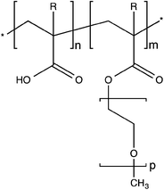 | ||
| Fig. 1 Example of a molecular structure of a polycarboxylate ether (PCE) superplasticizer. R = CH3 corresponds to methacrylic and R = H to acrylic acid or ester. | ||
In recent years however, there has been a shift of interest in using these polymers to help reduce the environmental footprint of concrete.19 To situate the magnitude of this specific issue, it is worth recalling that concrete is the most widely used material in the world and consequently has a significant impact on the environment. This comes predominantly from its binder: cement. The quantity of CO2 emitted during its production is about 1 kg per kg of clinker:† 30% from the fuels and 70% from decarbonation of limestone.20 With a production of 3.5 billion tonnes worldwide per year,21 the cement industry generates therefore 5–8% of man-made CO2 emissions.22 Reducing this represents one of the major environmental issues in the construction industry and one of the most promising solutions is to use blended cements. In such cements, part of the clinker is replaced by supplementary cementitious materials (SCMs) with a lower carbon footprint, such as fly ash (a waste-product of coal burning power plants).19,23
In this paper, we are concerned with the role of hydroxide ions. In concrete with high fly-ash replacements, these ions can play an important role in accelerating the strength development. This presents a major technological advantage, as fly ash otherwise reacts much slower than the cement it replaces, leading to performances that are not acceptable in normal construction. The reason for the use of hydroxides is that fly ash particles consist mostly of alumina-silicate glass with some crystalline constituents, such as quartz and various iron oxides. In most standards they can replace cement to 35%, coming mainly from their slow hydration and variable quality. However it has been shown that highly blended cements with 70% of fly ash may develop similar mechanical strength as standard cement just by incorporating alkaline activators in the system,24,25 leading to the precipitation of a mixture of amorphous gels C-S-H (from cement) and N-A-S-H‡ (from fly ash) responsible for the setting, hardening and thus the mechanical properties. The formation of this gel called “geopolymer” or “inorganic polymer” coming from the hydration of the fly ash is explained elsewhere.26,27 In the context of this paper we are however talking about much lower alkali additions. These would truly be considered as activators or catalysts, mainly acting on reaction kinetics rather than changing the nature of the final products.
Alkaline activation therefore represents a solution whereby minor additions could substantially enhance early reactivity, helping to overcome one of the presently greatest limitations to reducing clinker content in cement. Unfortunately, this solution has not been usable in practice for blended cements. As mentioned earlier, the use of hydroxides as an activator penalizes the flow properties of modern concrete designed for enhanced durability and containing PCEs.28 In the present work we specifically address this issue and propose a criterion allowing to a priori select, based on their molecular structure (Fig. 1), PCEs compatible with alkaline activation. Identifying comb copolymers that are effective dispersants in cement with high fly ash replacements has a very significant benefit in terms of sustainable construction and is from now on possible.
Firstly in this study, we report general observations on hydration of a superplasticized and alkaline activated blended cement paste. Then we illustrate how hydroxides modify the PCE performance. We show that this does not come from chemical changes but from reduced adsorption. This motivates a theoretical insight into thermodynamics of polymer adsorption and leads to the development of a criterion that defines for the first time whether polymers work or not in alkaline activated systems. This criterion takes the form of a simple equation in which its different parameters define the PCE molecular structure.29 Finally, to better illustrate the viability of this criterion, we show how a polymer selected in this way maintains its dispersing character in alkaline activated cement without compromising the enhanced strength development (shown with compressive strength on mortars).
Background
PCE superplasticizers
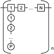 | ||
| Fig. 2 Schematic representation of a comb polymer. The polymer contains n segments with N monomers in the backbone, each segment having one side chain containing P monomers. | ||
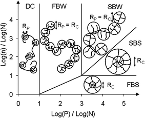 | ||
| Fig. 3 Phase diagram for comb homopolymer according to Gay and Raphaël30 and adapted by Flatt et al.31 The different domains are the following: decorated chains (DC), flexible backbone worm (FBW), stretched backbone worm (SBW), stretched backbone star (SBS) and flexible backbone star (FBS). Rc is the core size and Rp is the side chain size. | ||
The polymers studied in that project belong to the FBW (Flexible Backbone Worm) where the polymer can be viewed as an ideal chain of cores, each having a radius of gyration of Rc. Gay and Raphaël derived scaling laws that describe the size of these cores and the radius of gyration of such polymers as a function of their structural parameters n, N and P.
More recently, this approach was extended for a FBW comb copolymer both in solution and at interfaces.31 In that work it was observed by colloidal probe AFM that the comb copolymers used must have adsorbed with their backbone, but to a sufficiently low extent for their side chains to remain coiled. The first piece of evidence is that experimentally measured values of the adsorbed layer thickness are related to the length of the side chains through a power law of which the exponent is close to 0.6. In addition, these layer thicknesses are in quantitative agreement with a model describing the adsorbed polymers as chains of half spheres, which properly accounts for adsorbed layer thickness, steric hindrance and the surface occupied by polymers at surface saturation. In the context of this paper, we will use the scaling relation for the surface occupied (S1 and S2 in eqn (1) and (2)) by a given polymer, which is the same whether the polymer is assumed to deposit from solution or rearrange in the chain of half sphere conformation referred to above:
| S1 ≈ P9/10N3/10n | (1) |
We will also examine an alternative conformation described as a mushroom slice chain and that also implies coiled side chains:31
| S2 ≈ P3/4N9/16n | (2) |
It should be noted that in both cases these relations are less accurate as the side chain length decreases and render the scaling approach questionable. Also, in the case of a strongly adsorbing surface, one might expect the energy cost of side chain extension to be more affordable, so that the amount of polymers per unit surface could increase (the exponent of P would decrease and that of N would increase towards unity).
More recently, the role of PCE molecular structure in this behaviour was investigated.33 The key result was that sulphates affected the yield stress of cement pastes to an extent roughly proportional to P/N2.
While that result was simply deduced from the experimental observations, an associated paper34 examined the possible reasons for this specific dependence on molecular structure. Using first principle arguments for the effects of sulphates on PCE adsorption and of PCE adsorption on flow, it reached an expression for the effect of sulfates scaling as: P4/5N3/5(N − 1)−2. Within the range of structures investigated, this is similar or slightly better than P/N2. The main benefit from the scaling law derived theoretically is that it indirectly supports the assumption made to account for the effect of sulphates on the fluidity and in particular their competitive adsorption with PCEs. This derivation introduces an expression for the adsorption equilibrium of PCEs in relation to their molecular structure.34 This is also found to be effective in the presence of hydroxide ions, which is why we briefly summarise the underlying assumptions.
1. Polymers follow a Langmuir type adsorption isotherm.
2. The driving force for adsorption is electrostatic35 and competitive adsorption should be expressed with respect to surface charge sites.
3. Polymers compete with small ions that occupy most of the surface sites. Indeed the polymer only balances a small amount of the charges in the surface it covers owing to the coiled formation of its side chains.
4. The adsorption rate is expressed with regard to the total number of charges associated with the polymer and the solution as well as with the total number of free sites on the surface. This neglects the polymer structure role, which is incorporated into the adsorption kinetic constant discussed later.
5. The desorption rate is expressed with respect to the total number of charges associated with the polymer and present on the surface. Here again the polymer structure dependence is incorporated into the rate constant (here desorption).
The above assumptions lead to expressing the rate of occupancy of surface sites by the polymer as:
| Ra*A ≅ kaACAnz(N − 1)(1 − θ*B) | (3) |
| RdA = kdAθ*A | (4) |
| θ*A = θAnz(N − 1)/(SAρe) | (5) |
At equilibrium rates of surface charge occupancy and release are equal; so eqn (3) and (4) lead to:
| θ*A ≅ KACAnz(N − 1)(1 − θ*B) | (6) |
with the equilibrium constant:
| KA = kaA/kdA | (7) |
For the purpose of this paper, we now only examine how this constant is related to the molecular structure. In a first step, it is assumed that both adsorption and desorption rate constants depend on the polymer charge density per unit surface that they occupy. The adsorption and desorption rates are taken to be respectively proportional and inversely proportional to this charge density: n(N − 1)z/SA.
It is also assumed that owing to polymer rearrangement, the adsorption rate constant is also inversely proportional to its number of repeat units n (or number of PEO side chains). Using eqn (1) this gives:
| KA,1 ≈ (N − 1)2z2P−9/5N−3/5n−1 | (8) |
while using eqn (2) gives:
| KA,2 ≈ (N − 1)2z2P−3/2N−9/8n−1 | (9) |
It could also be argued that the additional inverse dependence on n might come from a reduced surface coverage when the number of segments is increased (owing to more difficulty to reach an optimal surface occupancy). For our purpose, we note that eqn (8) and (9) work well when analysing the effect of sulphates on a superplasticized cement paste and examine its relevance in the presence of hydroxides for this paper.
For convenience of graphical representation, we define:
| K*A,1 = 105KA,1 | (10) |
| K*A,2 = 105KA,2 | (11) |
As K*A,1 and K*A,2 showed similar trends when applied to the data of this study, only results obtained for K*A,1 are analysed in the next sections.
From flow spread test to yield stress
Flow properties of fresh cement pastes can be evaluated by simple and quick but relevant tests. They provide one simple parameter, which can be connected to a rheological property. One of the most important parameters to characterise the rheological behaviour of a cement paste is the yield stress (τ0). For fluid pastes, this parameter can be evaluated by a traditional test called the mini-flow spread test. In this test, a cone or a cylinder placed on a flat surface is filled with the cement paste. Then the cone or cylinder is lifted up to let the paste flow. The flow stops when the shear stress in the paste becomes smaller than the yield stress. Results of flow spread measurements are then converted into yield stress using eqn (12) that interpolates between the analytical limits of high and low spread:36,37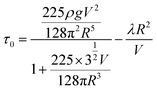 | (12) |
Experimental section
Materials
The cement used for the paste was an Ordinary Portland Cement CEM I 42.5N according to the European Standard EN 197-1 with a density of 3.1 g cm−3. During the investigations, the type of cement used in the paste was always the same but the dates of production of the cement batches and their storage were different. Some noticeable differences in the rheology between batches have been observed as discussed below. The fly ash used was Safament from Safa according to the European Standard EN 450 with a density of 2.3 g cm−3.The cement used for the mortar was a normal Portland Cement CEM I 42.5N according to the European Standard EN 197-1 (Normo 4 Holcim). The fly ash was Hydrolent (Holcim) according to the European Standard EN 450 with a density of 2.2 g cm−3. Aggregates consisted of sand with the gradation presented in Fig. 4.
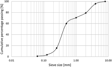 | ||
| Fig. 4 Grading curve of aggregates 0–4 mm. | ||
Among all the PCEs studied in this project, 2 PCEs (Table 1) have been chosen to investigate further the effect of hydroxides on them. PCE1 has been chosen because the nature of its backbone prevents the hydrolysis of the side chains.
| Backbone | Side chain | N | n | P | K*A,1 | K*A,1 (z = 1) | |
|---|---|---|---|---|---|---|---|
| PCE1 | Methacrylic acid | MPEG | 2.8 | 10 | 23 | 62 | 62 |
| PCE2 | Maleic acid | PEG | 3.8 | 5.1 | 25 | 615 | 248 |
Cement pastes: flow spread tests and calorimetry
Mortars: compressive strength
![[thin space (1/6-em)]](https://www.rsc.org/images/entities/char_2009.gif) :2. The mortar was mixed following the standard EN 196-1.
:2. The mortar was mixed following the standard EN 196-1.Results and discussion
Effect of NaOH on hydration of blended cement
Effects of the addition of hydroxides on the hydration of a blended cement are shown in Fig. 5 and 6. The substitution of cement by 30% wt of fly ash clearly reduces the total heat release due to the fact that in the first hours fly ash is largely inert. If we therefore assume that the heat release is only due to the cement in the blended paste and normalize data with respect to its weight (Fig. 6), we observe that up to 15 h the cumulative curves of the pure and blended cement pastes are quite similar. However, beyond this point, the blended cement paste presents a larger normalized cumulative heat release. This suggests that the dissolution of fly ash may have started. The addition of a small quantity of NaOH (0.5%) in the blended cement paste makes this happen already after 7 hours.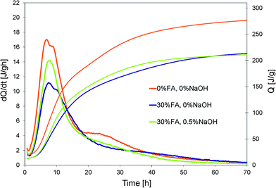 | ||
| Fig. 5 Influence of cement substitution by 30% wt of fly ash and addition of NaOH on the heat evolution of a blended cement paste. | ||
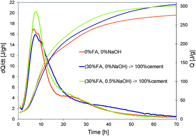 | ||
| Fig. 6 Normalization of heat evolution curves in Fig. 5 by weight of cement. | ||
The inclusion of a PCE in the mix can delay the hydration kinetics as shown in Fig. 7. The reference curve represents the normal system with 30% wt of fly ash without admixtures.
 | ||
| Fig. 7 Influence of different dosages of NaOH on the heat evolution of a superplasticized (PCE1) blended cement (from cement batch 1). | ||
PCE1 added at 0.1% retards hydration by about 5 hours. The addition of NaOH decreases this retardation from 5 to 3 hours (for 0.5% NaOH) or even cancel it (for 0.75% NaOH). However it also changes radically the shape of the heat release curve. Both maxima of the curve merge in only one peak and the global reaction becomes more exothermic. This is known to happen when the ratio of aluminates to sulphates increases. In our case this might also be the underlying reason as the addition of OH− can accelerate the dissolution of the aluminates that is very exothermic. This also typically changes the reactivity rates of both aluminate and silicate phases, which has very important implications in terms of strength development. While discussing this in detail would clearly be beyond the scope of this paper, we will note that in practice this issue is typically handled by varying the level of gypsum addition to cement. In this context, effects of gypsum additions between 1% and 3% are shown in Fig. 8. An addition of 1% of gypsum has no influence. With 2% of gypsum, the peak becomes larger and the global reactions seem to be less exothermic. With 3% of gypsum, the two maxima of the peak do not merge anymore and the global reaction is less exothermic. The shape of this curve (3% gypsum) shows similarities to those of the systems without NaOH. Thus the addition of gypsum does indeed allow changing the balance among aluminates, sulphates and silicates in a system with NaOH. This aspect will however not be investigated further as we will now rather focus on the loss of fluidity that the alkaline activation causes to superplasticized pastes.
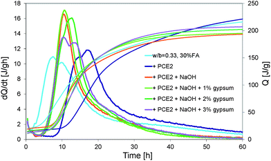 | ||
| Fig. 8 Heat evolution of a superplasticized (PCE2) blended cement (from cement batch 2) with 1%, 2% and 3% of gypsum. | ||
Effect of NaOH on the dispersive effect in blended cement
The loss of the dispersive effect of common PCEs in the presence of hydroxides was examined with flow spread tests. Results for reference blended cement pastes without admixtures, with PCE1 and with PCE1 and NaOH are shown in Fig. 9. They clearly show the substantial increase in yield stress that some superplasticized pastes can undergo when NaOH is added.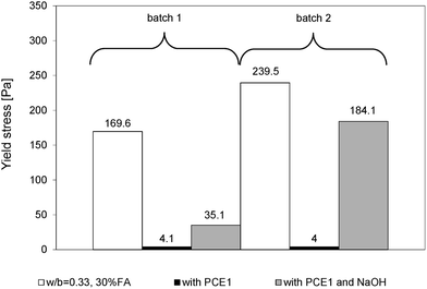 | ||
| Fig. 9 Yield stresses of superplasticized (PCE1) blended cement pastes made with two different batches of the same cement. For cement batch 1, the dosage of PCE1 was 0.1% and for cement batch 2, 0.12%. In both cases, the dosage of NaOH was 0.5%. | ||
The loss of the dispersive effect can be explained either by a change of adsorption degree, a change of dispersion capacity or a combination of both. It has been already mentioned that some PCEs can suffer structural changes in alkaline media by losing their side chains causing their reduced dispersing capacity.39 In our study, this is not the case as can be shown by some simple experiments in which NaOH was neutralised by corresponding additions of HCl (Fig. 10 and 11). This was done both on the polymer solutions kept either for 5 min or 18 hours in the NaOH solution as well as by adding the HCl directly into the paste. All experiments accounted for the water coming from the HCl solution. With the first cement batch, the solution neutralisation returns the yield stress to similarly low values as without NaOH addition (Fig. 10). Values are in fact equal to those obtained with NaCl additions. The polymer is therefore not modified. One may argue that these experiments do not include the extra alkalinity from the cement. This is why we also directly added the HCl to the cement paste. While the yield stress remains higher, it is nevertheless substantially lower than that without neutralisation. Again, this speaks strongly against a hydrolysis of the polymer. The conclusions are generally similar to those of the second cement batch although values are more scattered (Fig. 11).
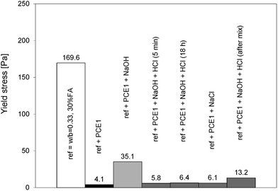 | ||
| Fig. 10 Yield stresses of blended cement (batch 1) after neutralization of hydroxides by HCl after 5 min, 18 hours and after the mixing and addition of NaCl in the superplasticized (PCE1) blended cement without NaOH. | ||
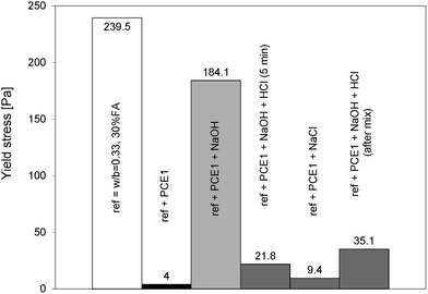 | ||
| Fig. 11 Yield stresses of blended cement (batch 2) after neutralization of hydroxides by HCl after 5 min and after the mixing and addition of NaCl in the superplasticized (PCE1) blended cement without NaOH. | ||
We found that the change in dispersion capacity can be related to a reduced adsorption of the PCEs in the presence of NaOH. This was shown by measuring PCE adsorption by solution depletion using Total Organic Carbon (TOC) measurements. Pastes made with cement batch 2 were used here because they showed a higher loss of fluidity (Table 2).
| PCE dosage % | NaOH dosage % | % of PCE remaining in pore solution |
|---|---|---|
| 0.1 | No | 56 |
| 0.1 | 0.5 | 93 |
For a paste without alkaline activation, almost half of the PCE added (56%) remained in the aqueous phase. When NaOH was added, 93% of the PCE used remained in the pore solution and thus was not used for dispersing. This explains why the yield stress of the paste with PCE and NaOH approached that of the paste without PCE. From these results, it can be concluded that the reduced dispersion of PCEs in highly alkaline media is not due to a change in their molecular structure or adsorbed conformation but due to a change of adsorption degree.
The reduced adsorption can have several reasons, possibly interlinked. For example, hydroxides may change the surface charge of cement. They may also displace Ca(OH)2 equilibrium, reducing the amount of calcium in solution, which is known to change surface charge to promote PCE adsorption. To some extent, these possibilities can be generically grouped under competitive adsorption between the polycarboxylate molecules and the hydroxides, which motivates the way in which this problem is discussed in the next section.
Sensitivity of PCEs to hydroxides
To study the link between the adsorption sensitivity to the hydroxides and the structure of the molecules, paste flow measurements were made with a large number of different PCEs. These differed by the length and the density of the side chains, the length of the backbone and the chemical nature of the monomers. However, they were all located in the same zone of Gay and Raphaël's phase diagram (Fig. 3): flexible backbone worm (FBW).For better comparison between PCEs that show different dispersive efficiencies, a relative yield stress change coefficient has been defined:
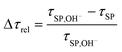 | (13) |
A simple comparison (not shown in this paper) between Δτrel and the parameters of the molecules, n, N and P, pointed out that there is no direct correlation between any individual parameter of the molecular structure and susceptibility to NaOH. However, the comparison with the constant K*A,1 (eqn (10)) defined by all the molecular parameters showed a clear trend (Fig. 12). In fact, this correlation is even improved if z, the number of charges per non-grafted monomer in the backbone, is systematically taken as unity (Fig. 13). At present we cannot rationalize this observation, other than by suggesting that it may come from a stronger calcium complexation by monomers with z > 1. However, assuming z = 1 provides a very useful relation for qualitative analysis of the dispersive effect of a wide range of polycarboxylate superplasticizers in different alkaline activated systems.29
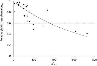 | ||
| Fig. 12 Relative yield stress change coefficient Δτrel function of the adsorption equilibrium constant K*A,1. Each dot represents a tested polymer. Under a Δτrel of 0.6, the polymers show a good resistance to the hydroxides. | ||
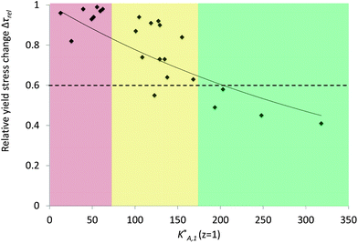 | ||
| Fig. 13 Relative yield stress change coefficient Δτrel function of the adsorption equilibrium constant K*A,1 calculated with the number of charges z = 1 for all types of monomers in the backbone. The part of the graph where K*A,1 is smaller than 70 represents polymers that are very sensitive to the hydroxides, the one where K*A,1 is higher than 175, the polymers that have a good resistance to them and the one in between, a “buffer zone” where polymers with the same K*A,1 value show totally different behaviors facing hydroxides. | ||
The correlation between K*A,1 (z = 1) and Δτrel respects two qualitative features expected (Fig. 13). First the relative yield stress change coefficient converges to unity when K*A,1 (z = 1) approaches zero and secondly values decrease with increasing K*A,1 (z = 1). The solid line is an exponential fit, which has the advantage of converging to zero as K*A,1 (z = 1) grows to infinity. Other fits may be more relevant, but this provides a good means for interpolation at this stage. It should be emphasized that scatter is not surprising since this plot combines different values of n, N and P as well as different backbone chemistries.
It has been observed that under a Δτrel of 0.6, the sensitivity to hydroxides is low or insignificant and corresponds to a K*A,1 (z = 1) value of at least 180. For example, PCE2, which is expected to be resistant to the hydroxides thanks to its K*A,1 (z = 1) value of 241, showed a Δτrel of 0.45. On the other hand, below a K*A,1 (z = 1) value of 80, it is certain that the sensitivity is high as demonstrated by PCE1 that has a K*A,1 (z = 1) value of 61 and a Δτrel of 0.98. However, between 80 and 180, it is not easy to define which PCE is resistant or not to hydroxides. For this reason the relation between the K*A,1 (z = 1) value and some polymers remains qualitative, although it provides a useful means to a priori identify which PCEs might be effective dispersants in alkaline activated blended cement. We may also note that exact values of Δτrel will depend on the cement condition as can be deduced from Fig. 9.
It has to be noted that the correlation is proposed for polymers with N smaller than 6. Indeed when the polymer is too ionic (i.e. when N is high), the interaction between the aluminate phases and the polymer is very fast and strong and impacts on the paste fluidity.40 This leads to very different and unstable yield stresses for the same dosage of polymer and therefore cannot be used to define the Δτrel.
Compressive strength of alkaline activated blended cements
Finally, as one of the aims of this study is to demonstrate that PCEs can be used in alkali-activated blended cements without loss of fluidity, flow spread and compressive tests have been performed on mortars with two levels of substitution of cement by fly ash (Fig. 14). To illustrate the difference between a compatible and an incompatible PCE, polymers PCE2, chosen thanks to K*A,1 (z = 1), and PCE1 were used respectively.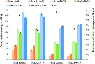 | ||
| Fig. 14 Yield stress and compressive strength at 1, 3 and 28 days of superplasticized (PCE1 and PCE2) blended mortars with 25% wt and 50% wt of fly ash. | ||
First of all, as indicated previously in the case of the cement pastes, PCE1 showed a high sensitivity to the hydroxides with a Δτrel between 0.89 (for 25% wt of fly ash) and 0.96 (for 50% wt). On the other hand, PCE2 confirmed its ability to work in a very alkaline medium with a Δτrel around 0.6. The slight increase of PCE2 sensitivity from 0.45 in the cement paste to 0.6 in the mortar is probably due to the higher dosage of NaOH used in the mortar (1.5% by weight of the binder instead of 0.5% in the cement paste).
It has to be noted that although PCE1 and PCE2 diverge notably in rheological performances with the addition of NaOH, they do not induce different effects on mechanical performance as compressive strengths are quite similar for the same level of substitution.
For both levels of substitution, the addition of NaOH clearly increases the compressive strength by about 50% for 25% wt of fly ash and 65% for 50% wt of fly ash after 1 day. However, after 3 days, the alkali activated mortars showed a lower strength than the mortar without NaOH. This probably comes from the negative effect that enhanced aluminate dissolution can have on the hydration of silicate phases.41 At 28 days, in the case of 25% wt of fly ash, the strength of the alkaline activated system is still lower than that of the system without hydroxides. However, the addition of NaOH in the system with the higher amount of fly ash slightly improved the compressive strength at 28 days. This is understandable given the fact that the contribution of fly ash to the strength increases with its content, and thus the impact of alkaline activation on the mechanical performances is more visible at higher fly ash content.
The purpose of using alkali activation is to substitute as much clinker as possible without impacting too much the mechanical strength at the early stage. From these data, it can be observed that after one day the compressive strength of a non-activated mortar with 50% wt of fly ash represents 36% of the strength of a non-activated 25% wt fly ash mortar. By adding NaOH, this percentage is almost doubled (60%), showing that higher substitution of cement by fly ash is possible in practice and can be done with the help of alkali activation to avoid high decrease of compressive strength. However, for this to be adopted in practice, a PCE compatible with hydroxides is needed and this paper shows how to select its ideal structure by using K*A,1.
Conclusions
Interactions between polycarboxylate superplasticizers and alkali-activated systems with 30% wt of fly ash have been studied. Firstly, from the point of view of hydration, data showed that the addition of NaOH accelerated hydration and decreased the retardation due to the PCEs.Rheological data showed a high loss of fluidity when a conventional PCE was used in the alkali-activated system. This was shown not to be due to a change in molecular structure such as a hydrolysis of the side chains but to a change of adsorption degree, probably due to a competitive adsorption with the hydroxyls. On this basis and in order to link the molecular parameters to the dispersive efficiency in such alkaline media, an adsorption equilibrium constant, K*A,1, calculated with these structural parameters, has been applied to rheological measurements of pastes dispersed with PCEs varying in their structure and chemistry. This was found to successfully rank the PCEs' susceptibility to hydroxides. For the first time, this criterion opens the door to the molecular design of PCEs compatible with alkali-activation systems and offers promising prospects to increase the substitution level of cement by not only fly ash but also other slowly reactive binders that have a lower environmental impact than clinker.
Acknowledgements
The authors would like to thank Heinz Richner (ETHZ) for assistance with the compressive strength measurements. They are also thankful to Dr Joerg Zimmermann and Dr Lukas Frunz (Sika Technology AG) as well as Dr Paul Bowen (EPFL) for useful discussion and/or comments.Notes and references
- N. Spiratos, M. Pagé, N. P. Mailvaganam, V. M. Malhotra and C. Jolicoeur, Superplasticizers for Concrete, Supplementary Cementing Materials for Sustainable Development Inc., Ottawa, 2003 Search PubMed.
- R. J. Flatt and I. Schober, in Understanding the Rheology of Concrete, Woodhead Publishing Limited, Cambridge, 2012 Search PubMed.
- G. H. Kirby and J. A. Lewis, J. Am. Ceram. Soc., 2004, 87, 1643–1652 CrossRef CAS.
- Y. F. Houst, et al., Cem. Concr. Res., 2008, 38, 1197–1209 CrossRef CAS PubMed.
- G. H. Kirby, D. J. Harris, Q. Li and J. A. Lewis, J. Am. Ceram. Soc., 2004, 87, 181–186 CrossRef CAS.
- E. Laarz, A. Kauppi, K. M. Andersson, A. M. Kjeldsen and L. Bergström, J. Am. Ceram. Soc., 2006, 89, 1847–1852 CrossRef CAS.
- E. Sakai, A. Kawakami and M. Daimon, Macromol. Symp., 2001, 175, 367–376 CrossRef CAS.
- C. P. Whitby, P. J. Scales, F. Grieser, T. W. Healy, G. Kirby, J. A. Lewis and C. F. Zukoski, J. Colloid Interface Sci., 2003, 262, 274–281 CrossRef CAS.
- J. Peng, J. Qu, J. Zhang, M. Chen and T. Wan, Cem. Concr. Res., 2005, 35, 527–531 CrossRef CAS PubMed.
- J. Plank, K. Pöllmann, N. Zouaoui, P. R. Andres and C. Schaefer, Cem. Concr. Res., 2008, 38, 1210–1216 CrossRef CAS PubMed.
- F. Winnefeld, S. Becker, J. Pakusch and T. Götz, Cem. Concr. Compos., 2007, 29, 251–262 CrossRef CAS PubMed.
- J. Plank and B. Sachsenhauser, J. Adv. Concr. Technol., 2006, 4, 233–239 CrossRef CAS.
- S. Lee, M. Müller, M. Ratoi-Salagean, J. Vörös, S. Pasche, S. M. De Paul, H. A. Spikes, M. Textor and N. D. Spencer, Tribol. Lett., 2003, 15, 231–239 CrossRef CAS.
- R. J. Flatt, Y. F. Houst, P. Bowen, H. Hofmann, J. Widmer, U. Sulser, U. Maeder and T. A. Bürge, in Proc. 5th Canmet/ACI Int. Conf. Superplasticizers and Other Chemical Admixtures in Concrete, Detroit: ACI, 1997, SP-173, pp. 743–762 Search PubMed.
- K. Yamada, S. Ogawa and S. Hanehara, Cem. Concr. Res., 2001, 31, 375–383 CrossRef CAS.
- J. Plank and C. Winter, Cem. Concr. Res., 2008, 38, 599–605 CrossRef CAS PubMed.
- J. Plank, A. Brandl and N. Recalde Lummer, J. Appl. Polym. Sci., 2007, 106, 3889–3894 CrossRef CAS.
- R. J. Flatt and P. Bowen, Cem. Concr. Res., 2003, 33, 781–791 CrossRef CAS.
- R. J. Flatt, N. Roussel and C. R. Cheeseman, J. Eur. Ceram. Soc., 2012, 32, 2787–2798 CrossRef CAS PubMed.
- J.-P. Ollivier and A. Vichot, La Durabilité des Bétons, Presses de l'Ecole Nationale des Ponts et Chaussées, Paris, 2008 Search PubMed.
- http://www.cembureau.eu/about-cement/key-facts-figures, October 2012.
- E. Worrell, L. Price, N. Martin, C. Hendriks and L. Ozawa Meida, Annu. Rev. Energy Environ., 2001, 26, 303–329 CrossRef.
- B. Lothenbach, K. Scrivener and R. D. Hooton, Cem. Concr. Res., 2011, 41, 1244–1256 CrossRef CAS PubMed.
- A. Palomo, A. Fernandez Jimenez, G. Kovalchuk, L. M. Ordoñez and M. C. Naranjo, J. Mater. Sci., 2007, 42, 2958–2966 CrossRef CAS.
- C. Shi, A. Fernandez Jimenez and A. Palomo, Cem. Concr. Res., 2011, 41, 750–763 CrossRef CAS PubMed.
- P. Duxson, A. Fernandez Jimenez, J. L. Provis, G. C. Lukey, A. Palomo and J. S. J. van Deventer, J. Mater. Sci., 2007, 42, 2917–2933 CrossRef CAS.
- J. S. J. van Deventer, J. L. Provis, P. Duxson and G. C. Lukey, J. Hazard. Mater., 2007, 139, 506–513 CrossRef CAS PubMed.
- M. Palacios and F. Puertas, Cem. Concr. Res., 2005, 35, 1358–1367 CrossRef CAS PubMed.
- D. Marchon, U. Sulser, A. Eberhardt and R. J. Flatt, Comb polymers as dispersants for alkaline-activated binders, WO2012172040 (A1), 2012.
- C. Gay and E. Raphaël, Adv. Colloid Interface Sci., 2001, 94, 229–236 CrossRef CAS.
- R. J. Flatt, I. Schober, E. Raphael, C. Plassard and E. Lesniewska, Langmuir, 2009, 25, 845–855 CrossRef CAS PubMed.
- K. Yamada and S. Hanehara, Concr. Sci. Eng., 2001, 3, 135–145 CAS.
- J. Zimmermann, C. Hampel, C. Kurz, L. Frunz and R. J. Flatt, in 9th ACI International Conference on Superplasticizers and Other Chemical Admixtures in Concrete, Seville, Spain: ACI, 2009, SP-262, pp. 165–176 Search PubMed.
- R. J. Flatt, J. Zimmermann, C. Hampel, C. Kurz, I. Schober, C. Plassard and E. Lesniewska, in 9th ACI International Conference on Superplasticizers and Other Chemical Admixtures in Concrete, Seville, Spain: ACI, 2009, SP-262, pp. 153–164 Search PubMed.
- C. Labbez, M. Medala, I. Pochard and A. Nonat, 2nd International Workshop on Mechanisms and Modelling of Waste/Cement Interactions, France, 2008 Search PubMed.
- N. Roussel and P. Coussot, J. Rheol., 2005, 49, 705–718 CrossRef CAS.
- N. Roussel, C. Stefani and R. Leroy, Cem. Concr. Res., 2005, 35, 817–822 CrossRef CAS PubMed.
- D. Lootens, R. J. Flatt and P. Juilland, in Concreep 8: 8th International Conference on Creep, Shrinkage and Durability of Concrete and Concrete Structures, CRC Press, 2008, pp. 305–308 Search PubMed.
- M. Palacios and F. Puertas, Mater. Constr., 2004, 54, 65–86 CAS.
- C. Giraudeau, J.-B. d'Espinose de Lacaillerie, Z. Souguir, A. Nonat and R. J. Flatt, J. Am. Ceram. Soc., 2009, 92, 2471–2488 CrossRef CAS.
- A. Kumar, G. Sant, C. Patapy, C. Gianocca and K. L. Scrivener, Cem. Concr. Res., 2012, 42, 1513–1523 CrossRef CAS PubMed.
Footnotes |
| † Clinker is the product of sintering limestone and alumino-silicate from clays in a cement kiln. It is called Portland cement after the addition of gypsum during the grinding process. |
| ‡ C-S-H stands for calcium silicate hydrate and is the main product of Portland cement hydration primarily responsible for strength of cementitious materials. N-A-S-H stands for sodium alumino-silicate hydrate and is the main product of alkali-activated fly ash hydration. |
| This journal is © The Royal Society of Chemistry 2013 |