 Open Access Article
 This Open Access Article is licensed under a
 Creative Commons Attribution 3.0 Unported Licence
Computational prediction and experimental confirmation of B-site doping in YBa2Fe3O8†
Christopher
Collins
a,
Matthew S.
Dyer
a,
Antoine
Demont
a,
Philip A.
Chater
a,
Michael F.
Thomas
b,
George R.
Darling
a,
John B.
Claridge
a and
Matthew J.
Rosseinsky
*a
aDepartment of Chemistry, University of Liverpool, Crown Street, Liverpool, L69 7ZD, UK. E-mail: rossein@liv.ac.uk
bDepartment of Physics, University of Liverpool, Liverpool, L69 7ZE, UK
First published on 3rd January 2014
Abstract
In this work we use calculations to obtain reaction enthalpies for the formation of YBa2Fe3−xMxO8 (where M = Co, Ni and Mn and x = 1, 2 and 3) from binary oxides and oxygen gas using Density Functional Theory (DFT). Based upon these calculations we are able to make predictions on favourable levels of doping and B-site ordering for YBa2Fe3−xMxO8, followed by experimental investigation in the same study. The composition where we predict doping to be favourable was experimentally investigated and a triple perovskite is found to be the major phase, confirming the prediction. Optimisation of the synthesis produced a phase-pure triple perovskite, Y1.175Ba1.825Fe2MnO8±δ, formed in a narrow compositional window. The crystal structure of this phase was analysed using Powder X-ray Diffraction (PXRD), iodometric titrations, Mössbauer spectroscopy and Neutron Powder Diffraction (NPD). This is the first reported example of ordered or disordered Fe and Mn coexistence in this structure type. We compare the observed structure against the initial DFT predictions and find them to be in good agreement and conclude that the computational methods presented within this work can be used as a predictive guide to the synthesis of oxide materials.
Introduction
The properties of transition metal oxides are controllable by substitution at the metal sites. When several candidate sites are available, qualitative crystal chemical considerations may not always be capable of predicting the outcome of a substitution reaction. Here we explore the use of ab initio calculations to define the outcome of site substitution in an ordered triple perovskite.Complex metal oxides are important scientifically because of their structural diversity and the wide range of novel phenomena they sustain, including charge ordering, colossal magnetoresistance and multiferroic behaviour. They have applications in many industrial and technological areas including catalysis,1 solid oxide fuel cell (SOFC)2 electrolytes and electrodes, transparent conductors,3 superconductors,4 ferro- and piezoelectrics,5 dielectric materials,6 thermoelectrics,7 positive temperature co-efficient of resistivity materials (PTCR)8 and ferrite permanent magnets.9 Substitution into a parent structure permits property tuning in all of these application classes – examples are the evolution of the d.c. conductivity and area specific resistance (ASR) in the Ba1−xSrxFe1−yCoyO3−δ10–13 family of SOFC cathode materials, and band gap and resistivity tuning in the doped ZnO14–16 family of transparent conducting oxides.
The structure of the superconductor YBa2Cu3O7 (ref. 17) is based upon the ABO3 perovskite structure that is extended to form a three-fold super structure in the c-axis direction, hereafter referred to as a 3ap structure. YBa2Fe3O8 (ref. 18) (Fig. 1a) was the first 3ap analogue of the superconductor YBa2Cu3O7 in which Cu was fully replaced by another transition metal, and hence has been the object of considerable study.18–23 It is a good candidate for predictive substitution as it is related to a number of other functional oxide materials in terms of system size,17,24 structural motif17,25 and some of the elements included in the system have been previously reported in other functional systems.10,17,25 Long range ordering in the c direction is driven by ordering of oxygen vacancies (one ninth per triple perovskite (A3B3O9) Formula Unit (FU)). These ordered vacancies create distinct A- and B-site environments within the structure. There are three A-sites, one hosting Y3+ ions co-ordinated to eight O2− ions and two Ba sites co-ordinated to twelve O2− ions. The B-sites are five co-ordinate square based pyramids and six co-ordinate octahedral sites, both distorted away from ideal polyhedral geometry: the octahedral site has four short and two long bonds, and the square pyramidal site has one short and four long bonds. YBa2Fe3O8 orders antiferromagnetically at ∼700 K (ref. 20–22) with a G-type magnetic structure.23
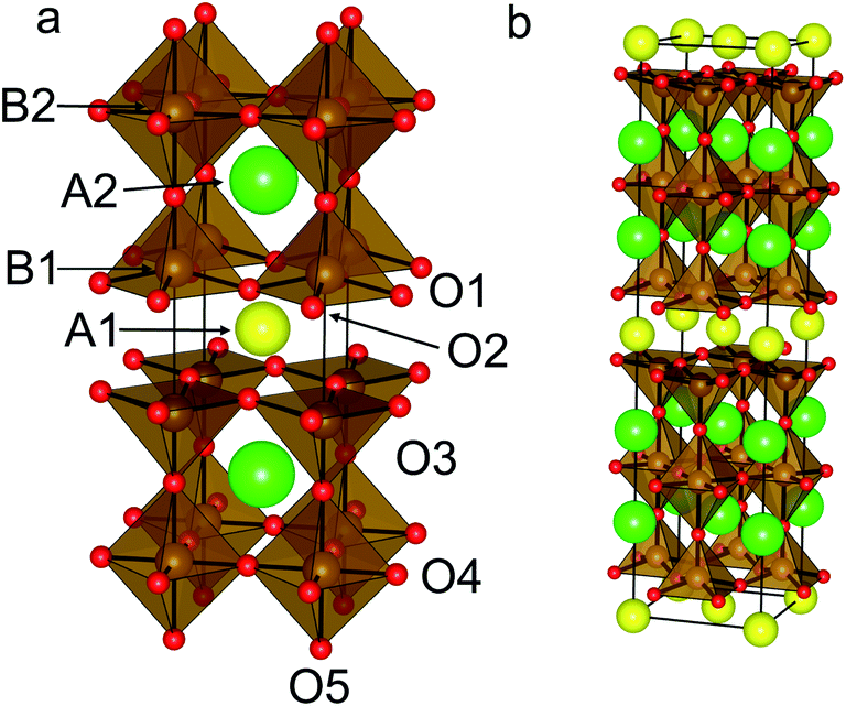 | ||
| Fig. 1 (a) Reported structure for YBa2Fe3O8, including the atomic labels used in this study. With tetragonal symmetry O1 and O2 are equivalent. (b) (a + b, a − b, 2c) super-cell used in DFT calculations. Atoms coloured as follows: Y (yellow), Ba (green), Fe (brown) and O (red). | ||
In this work we explore the use of Density Functional Theory (DFT) to guide the synthesis of B-site doped YBa2Fe3O8.18 While previous reports exist for substitution of Co into the YBa2Fe3O8 compound,19 substitution with Ni or Mn is currently unreported. This allows for both the validation of the computational method for the system by calculating Co substitution and for the prediction of unreported substitutions. Irrespective of the A-site composition, no compounds containing Fe and Mn have been previously reported in this structure.
Given the multiplicity of possible sites for doping, it is not trivial to identify where a substitution will take place. Prediction of whether a dopant will favour one of the available B-site geometries by looking at known structures is not reliable as precedents exist for doping at each of the sites found in the 3ap structure.26–28 It is also possible that B-site doping may occur in a disordered fashion over both B-sites. Given the widespread applicability of doped metal oxides it is highly desirable to use calculations to aid in predicting how to substitute the compound in order to reduce the number of syntheses that are required to find new compounds.
The calculation of stable levels of doping in YBa2Fe3O8 is a complex computational problem because of the number of metal species present and two different chemical environments for Fe3+. The prediction of ionic substitution based on a database of structures has been reported previously.29 It has also been shown that all unique configurations of a structure can be generated using symmetry, and the most stable configuration determined by calculating relative energies between configurations.30 This method has been applied in calculating the solid solutions of some binary and ternary oxides31–33 and carbonate systems34,35 and for a number of other system types.36–38 Convex hull calculations have also been previously used in the prediction and synthesis of compounds with some success,39 however the construction of convex hulls for systems containing four or more elements is impractical.
The complex structures of many functional transition metal oxides require large numbers of potential disordered configurations to be investigated in an exhaustive study. For example the largest super-cell used here for the composition YBa2Fe2MnO8 has 16 Fe atoms and 8 Mn atoms distributed over 24 B-sites. Ignoring symmetry, there are 24!/16!8! = 735![[thin space (1/6-em)]](https://www.rsc.org/images/entities/char_2009.gif) 471 ways of arranging these atoms, which reduces to 24371 configurations not related by symmetry. Since such an exhaustive approach is clearly unfeasible in this case, we propose a more practical, simplified model. Previously it has been shown that DFT calculations can be configured to closely reproduce experimental reaction enthalpies for previously known perovskite materials, such as the LaMO3 system, where M indicates a transition metal species40,41 for calculations performed at 0 K. This work utilises the capability of DFT to calculate formation energies from binary oxides as a predictive tool, and is demonstrated in a system containing four different cation species and covering three different dopants with a range of doping levels.
471 ways of arranging these atoms, which reduces to 24371 configurations not related by symmetry. Since such an exhaustive approach is clearly unfeasible in this case, we propose a more practical, simplified model. Previously it has been shown that DFT calculations can be configured to closely reproduce experimental reaction enthalpies for previously known perovskite materials, such as the LaMO3 system, where M indicates a transition metal species40,41 for calculations performed at 0 K. This work utilises the capability of DFT to calculate formation energies from binary oxides as a predictive tool, and is demonstrated in a system containing four different cation species and covering three different dopants with a range of doping levels.
We begin by calculating an energy of M substitution for doped YBa2Fe3−xMxO8 in a selected number of B-site configurations, representative of the possible orderings. We then experimentally test the following hypothesis: when this substitution energy is negative, doping will be experimentally favourable and conversely when the substitution energy is positive, doping would be unfavourable. We demonstrate the methodology for YBa2Fe3−xMxO8 when M = Co which has previously been synthesised19 and then make predictions for doping when M = Mn and Ni.
Reaction energies
We start our calculation of reaction enthalpies by defining the dopant species M* by the binary oxide of M and a required amount of O2 gas required to balance any change in the charge state of M in the doped compound to the 3+ oxidation state: | (1) |
For reference calculations of the energies of binary oxides, the initial atomic coordinates and unit cells were used as reported in the literature.42–47 Where multiple possible binary oxides are reported for the transition metals (M = Co and Mn) the oxide which gave an overall charge state as close to 3+ as possible was selected in order to minimise the amount of O2 required to balance the equation. When M = Mn, no change in formal oxidation state is required, for M = Co and Ni, we assume that all of the M atoms increase their average oxidation state to be formally 3+ as this is reported experimentally for Co in this system.19
A substitution energy, ΔEsub, can then be defined for the formation of the doped material from the undoped parent, binary oxides and gas phase oxygen where required (Eqn (2)).
 | (2) |
The most favoured configuration at each doping level is defined as the composition that yields the lowest substitution energy, ΔEsub. A negative value of ΔEsub is used across doping species and doping levels to predict that doping is likely to be possible. The energy ΔEsub is closely related to other potentially relevant reaction energies, as discussed in the ESI.†
Since we are calculating energies at each end of the solid solution and values in between, we can also calculate energies relative to an ideal solid solution. Particularly stable compositions might be expected to have energies that lie below the energy of the ideal solid solution. Alternatively increases in energy indicate that the solid solution is unfavourable as has been suggested for solid solutions between binary materials,48 which could suggest that phase separation is likely. For our systems, a solid-solution energy, ΔESS, is calculated according to Eqn (3):
 | (3) |
In the system examined in this work the YBa2M3O8 end members of the solid solutions are not reported in ordered 3ap structures (although YBa2Co3O8+δ is reported as a disordered cubic perovskite49), and so the solid-solution energy is not a true prediction of phase stability (competing phase separation into the two ordered end members cannot occur experimentally). Instead we use ΔEsub (Eqn (2)) for our predictions of the outcomes of substitution reactions (Fig. 3a). However, for clarity in identifying the differences between configurations at each value of x we have used ΔESS (Eqn (3) and Fig. 3b–d).
Doping models
The initial atomic coordinates and unit cell for the calculations were taken from the reported crystal structure of YBa2Fe3O8 in an (a + b, a − b, 2c) super-cell of the nuclear cell (Fig. 1b).18 This super-cell allows calculations for G-type antiferromagnetic and ferromagnetic ordering, and contains four octahedral and eight square pyramidal B-sites, over which the various transition metal cations were distributed at each level of doping.The different B-site configurations considered for different doping levels are shown in Fig. 2. For full substitution (x = 3) only one B-site configuration is possible. For x = 1 and 2, three different B-site configurations were considered in order to be able to approximate the site preferences of the dopant species. In the first configuration, which we named “Octahedral”, octahedral sites are preferred for the dopant species. At the doping level of x = 1 the octahedral sites are filled, and hence for x = 2 the remaining dopants were distributed evenly amongst the square pyramidal sites in order to maximise the separation between the dopant atoms (Fig. 2). In the second configuration, which we name “Square Pyramidal” the dopant species were distributed amongst alternating square pyramidal site at x = 1 and the square pyramidal sites were fully occupied when x = 2. For the final “Mixed” configuration the calculations were performed on a larger (2(a + b), a − b, 2c) super-cell to allow for each of the two octahedral and the four square pyramidal layers to contain the same number of dopant atoms. For both x = 1 and x = 2 an equal number of dopant species were placed on each type of B-site, with the atoms distributed in order to maximise their separation (Fig. 2).
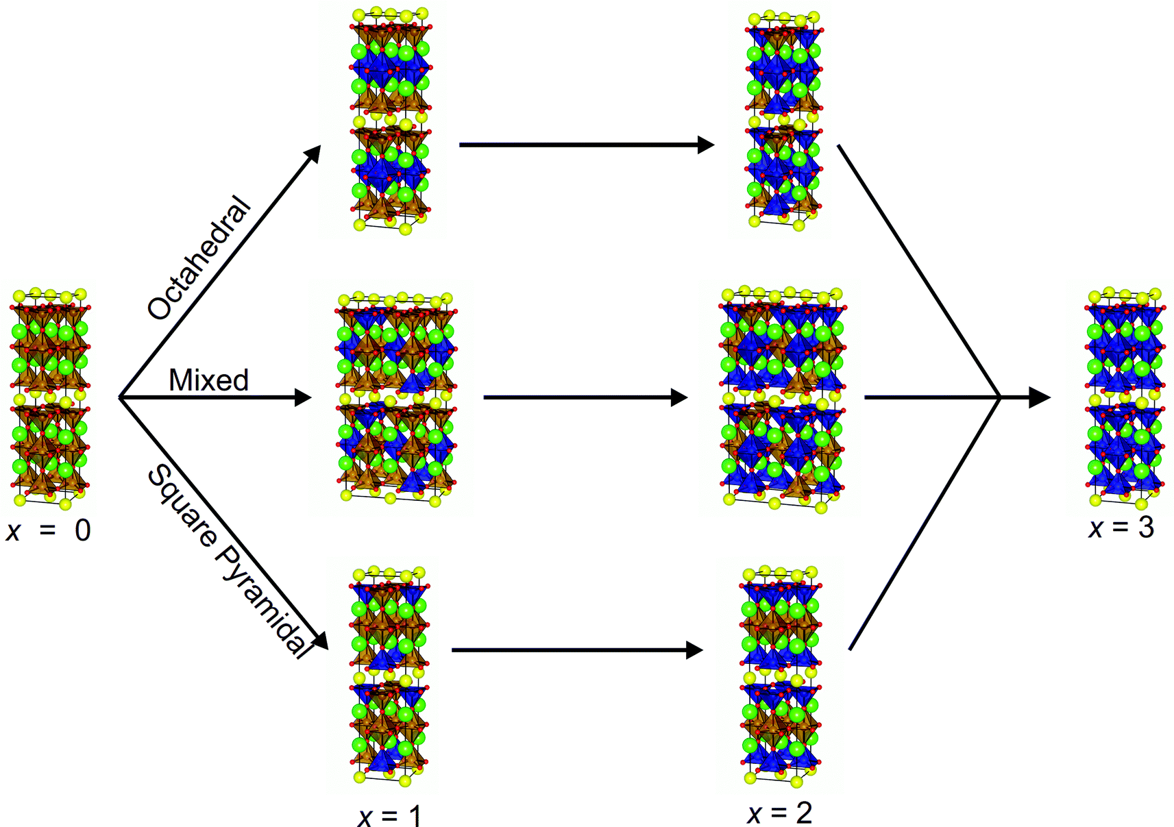 | ||
| Fig. 2 Structures used for DFT calculations with the three different site preferences (octahedral, square pyramidal and mixed) at doping levels x = 1 and 2. Atoms coloured as follows: Y (yellow), Ba (green), Fe (brown), dopant (blue) and oxygen (red). | ||
Computational results
Balanced equations for the calculation of substitution energies were created taking into account the possibility of an overall change in oxygen content, depending on the dopant metal (ΔEsub, Eqn (2)). Calculated values of ΔEsub are used to predict whether a calculated composition would be stable (negative ΔEsub) and therefore likely to form experimentally.Results for the calculated substitution energies suggest that favourable doping can be achieved when M = Co and Mn and no favoured doping configuration was found when M = Ni. Substitution energies for the lowest energy configuration for each doping level and dopant are shown in Fig. 3a. When M = Co the x = 1 substitution level is favoured with ΔEsub = −0.03 eV/FU when the dopant atoms are distributed over octahedral and square-pyramidal sites in the Mixed configuration, i.e. with no B-site preference (Fig. 3b). At higher doping levels of x = 2 and 3, doping is calculated to be unfavourable, with positive values of ΔEsub. The calculation of favourable doping for M = Co and x = 1 without any B-site preference which becomes unfavourable at a point between x = 1 and 2 is in good agreement with reported experimental results.19 Co doping within the YBa2Fe3O8 phase has been reported for the nominal values of x = 0.6, 0.9, 1.2 and 1.5, and substitution beyond x = 1.5 has not been reported experimentally. In addition, experiments show no significant cation site preference for the doped compounds.19 The consistency between the computational results and the experimentally reported phases suggest that our approach can reliably calculate the favourability of transition metal substitution within YBa2Fe3O8.
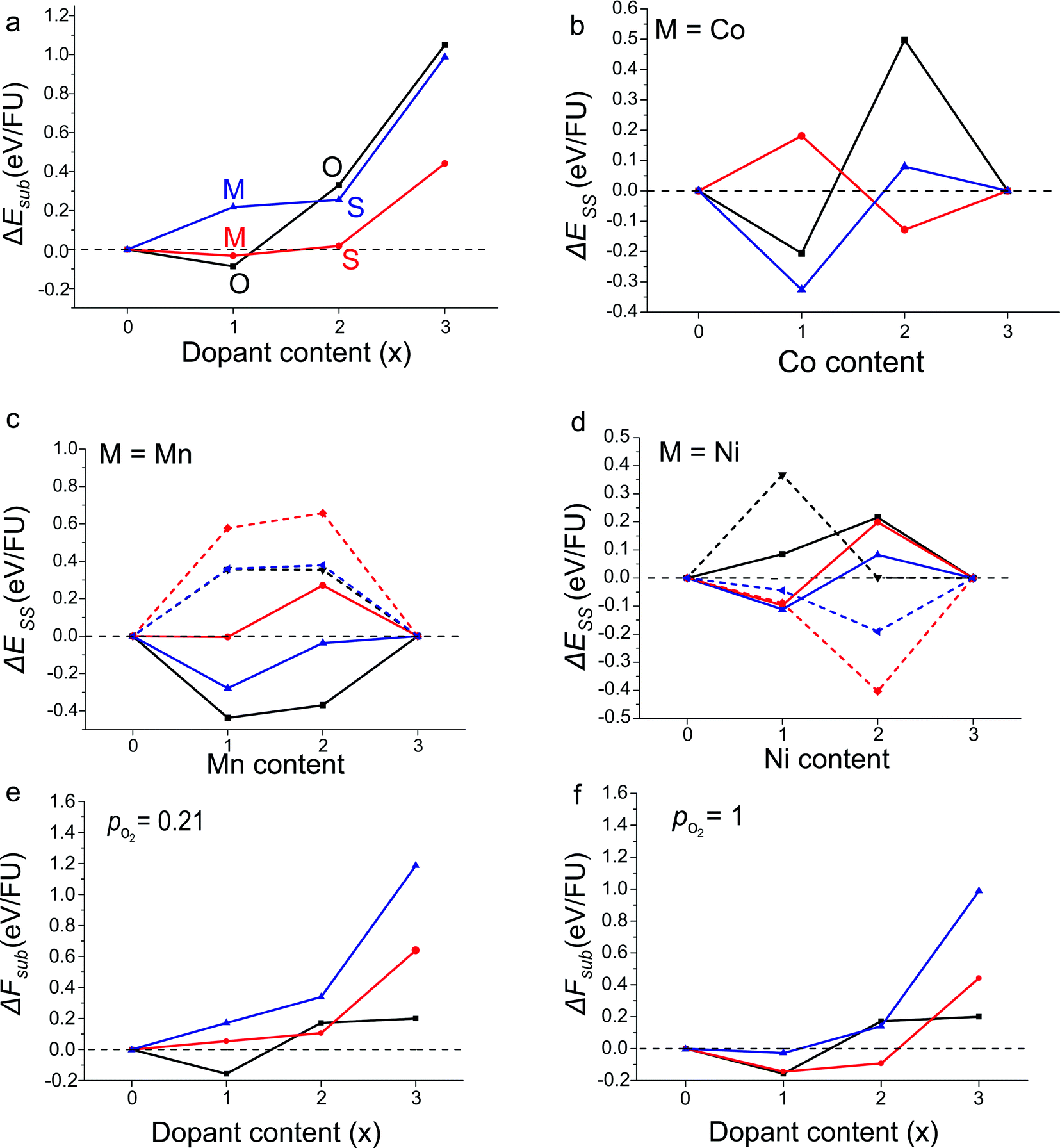 | ||
| Fig. 3 (a) Calculated reaction energies, ΔEsub, for the most stable configuration at each doping level for YBa2Fe3−xMxO8 calculated according to Eqn (2), for M = Mn (black), Co (red) and Ni (blue). The most stable configuration is indicated by the letters (octahedral), (mixed) and (square pyramidal). (b and c) Solid-solution energies, ΔESS, for all configurations and dopant species calculated according to Eqn (3). The octahedral (black), square pyramidal (red) and mixed (blue) configurations are plotted with solid lines for antiferromagnetic order and dashed lines for ferromagnetic order where calculated. ΔESS = 0 in (c and d) to guide the eye. (e and f) Reaction free energies, ΔFsub, calculated at 1473 K with partial oxygen pressures corresponding to air and pure O2 at atmospheric pressure. Colours as in panel (a). | ||
For M = Mn calculations suggest that substitution is favoured at x = 1, with the Mn atoms in the octahedral configuration with G-type antiferromagnetic ordering on the B-site (Fig. 3c). ΔEsub for the substituted material was calculated to be −0.09 eV/FU. The higher x = 2 substitution level is considerably unfavourable energetically; the most stable configuration has the Mn atoms in the octahedral configuration with G-type antiferromagnetic ordering but the substitution energy, ΔEsub, is +0.33 eV/FU.
For M = Ni, no substitution level is found to have a negative value of ΔEsub. An interesting result to note however, is that at x = 2 the Ni atoms were favoured in the square pyramidal sites and with ferromagnetic ordering (Fig. 3d). Although the x = 2 configuration was found to have a positive ΔEsub value of +0.26 eV/FU, if this level of doping could be synthesised in the 3ap structure, our calculations predict that the material would unusually favour ferromagnetic over G-type antiferromagnetic ordering.
In summary, the DFT calculations predict that only x = 1 Mn substitution is favourable from the six Ni and Mn substitution levels examined.
As expected, of the calculated structures we observe that for each doping level, the most stable configuration also has the smallest unit cell volume (Fig. 4a–c). The single exception was when x = 1 and M = Ni, where the configuration with the smallest unit cell volume is 0.014 eV/FU less stable compared to the structure with the lowest energy.
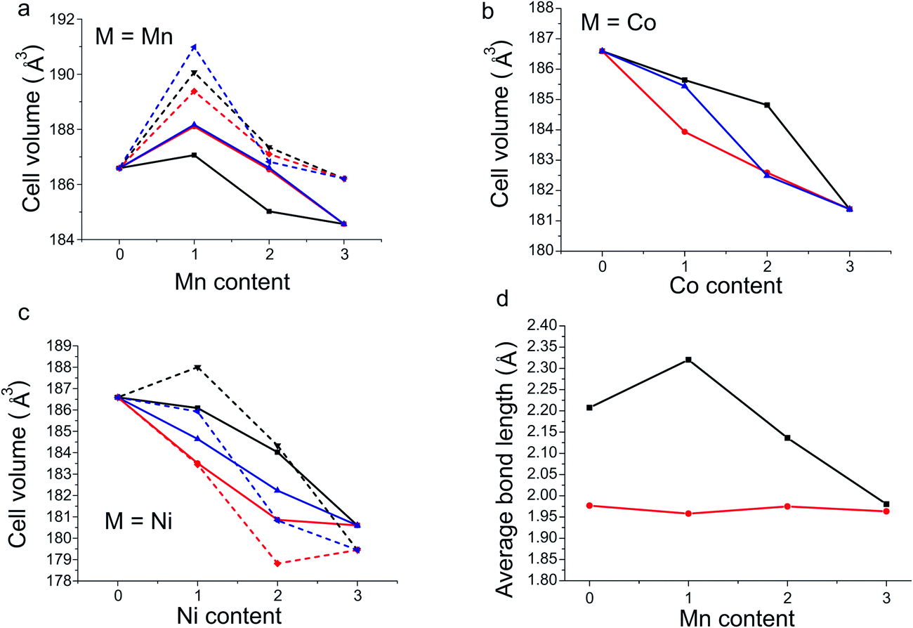 | ||
| Fig. 4 (a–c) DFT unit cell volumes as a function of dopant content for Mn, Co and Ni. The octahedral (black), square pyramidal (red) and mixed (blue) configurations are plotted with solid lines for antiferromagnetic order and dashed lines for ferromagnetic order. (d) DFT calculated bond lengths for the axial (black) and equatorial (red) M–O bonds of the octahedral site as a function of Mn doping in the octahedral configuration of YBa2Fe3−xMnxO8. | ||
In the structure of the M = Mn, x = 1 octahedral configuration, which is predicted to be stable, the geometries (Fig. 4d) of the fully Mn occupied octahedral sites display a sharp increase in the distortion of the octahedral coordination environment when compared to the undoped material. The axial bond length increases by 0.11 Å with a concurrent shortening of the equatorial bond by 0.02 Å in line with the Jahn–Teller distortion expected for Mn3+ (Fig. 4d). When the doping level is increased (x = 2 and 3) the length of the equatorial bond changes little. However, the extra Mn atoms must be placed into square pyramidal sites, shortening one axial bond of the octahedron and creating an irregular octahedral site, with two long bonds (2.00 and 2.28 Å) and four short bonds with a mean length of 1.97 Å. Similarly at the doping level x = 2, where extra Mn atoms occupy half the square pyramidal sites, the square pyramid coordination environment distorts relative to the undoped material, resulting in four different square pyramids each with differing bond lengths. We suggest that the inclusion of Mn when x is greater than 1, forcing Mn into the square pyramidal sites and causing considerable distortion of all B-sites, is a factor which leads to the increased levels of doping becoming unfavourable.
The results presented above are based solely upon DFT ground state energies, however to predict the relative stability of phases under experimental conditions, it may be necessary to include the effects of finite temperature by calculating free energies of reaction. Free energies for the reaction shown in Eqn (2), ΔFsub, have been calculated including contributions from the entropy of mixing and the free energy of gas phase O2 (see ESI† for details).
Values of ΔFsub calculated at the synthesis temperature of 1473 K, and with partial oxygen pressures corresponding to air and pure O2 at atmospheric pressure are shown in Fig. 3e and f. Qualitatively, the results follow closely those calculated at 0 K. All Ni doped compositions remain unstable at atmospheric partial oxygen pressure, although the data suggest that YBa2Fe2NiO8 may be stable under an atmosphere of pure O2, which is more oxidising than any conditions used experimentally in this study. Of the Mn doped compositions, YBa2Fe2MnO8 retains a negative reaction energy and is predicted to be stable. The largest differences are seen in the Co doped compositions. Under air (pO2 = 0.21) all Co doped compositions become unstable relative to YBa2Fe3O8, Co3O4 and O2; only under the more oxidising pure O2 atmosphere (pO2 = 1) is YBa2Fe2CoO8 predicted to be stable. This is entirely in line with experiment, as synthesis of Co doped YBa2Fe3O8 is carried out under flowing O2.19 In the present study, the conclusions drawn from pure DFT data, calculated at 0 K, would have been the same as those drawn from the free energy data. This may, however, not always be the case, and as our thermodynamic analysis required very little extra computational cost, we suggest that it should be carried out in any future studies which use a similar methodology.
Experimental results
To test both positive and negative predictions of doping levels, samples were synthesised at the composition YBa2Fe2MnO8±δ (M = Mn, x = 1), which is predicted to be stable, and the compositions representing YBa2FeNi2O8±δ (M = Ni, x = 2) and YBa2FeMn2O8±δ (M = Mn, x = 2), predicted to be unstable. Synthesis was attempted in air and under a reducing atmosphere of flowing N2.In the sample with the composition YBa2FeNi2O8±δ fired under flowing N2 (Fig. 5a), it is observed that the sample contains a mixture of known binary and ternary oxide phases, with no formation of phases with the 3ap structure. In the sample of composition YBa2FeMn2O8±δ (Fig. 5b), the major phase was indexed to be a hexagonal perovskite similar to the reported 4H BaMnO3−δ,33 along with two tetragonal or pseudotetragonal perovskite phases. One has lattice parameters of ap = 3.9270(2) Å and cp = 3.8380(4) Å, consistent with the double perovskite YBaMn2O5.28 The other has perovksite lattice parameters of ap = 3.9004(9) Å and cp = 3.926(1) Å which are not consistent with any known phase containing these elements. No long range order peaks arising from a 3ap phase were observed. The phases observed in YBa2FeNi2O8±δ and YBa2FeMn2O8±δ are in agreement with the predictions from DFT, in that a single 3ap perovskite was not formed as the major phase in either sample.
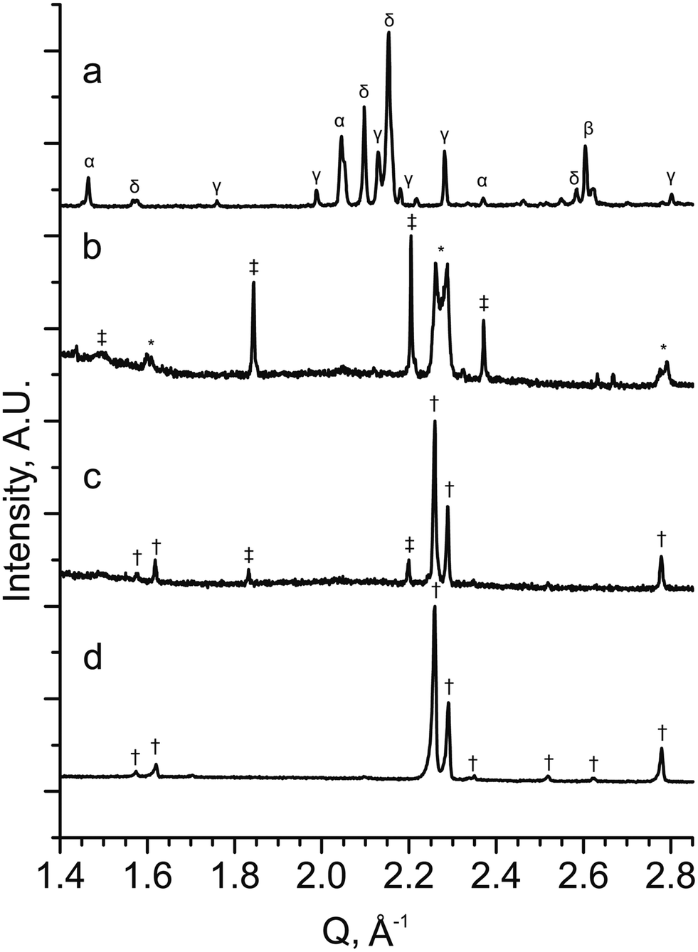 | ||
| Fig. 5 PXRD patterns from stoichiometric samples of YBa2Fe3−xMxO8±δ for (a) M = Ni and x = 2 (YBa2FeNi2O8±δ), (b) M = Mn and x = 2 (YBa2FeMn2O8±δ) and (c) M = Mn and x = 1 (YBa2Fe2MnO8±δ) (d) YBa2Fe2MnO8±δ with an optimised Y:Ba ratio (Y1.175Ba1.825Fe2MnO8±δ) when synthesised under a N2 atmosphere. The XRD patterns show that no 3ap perovskite is formed in YBa2FeNi2O8±δ, with a mixture of oxide phase identified (α = Y2O3, β = NiO, γ = BaY2NiO5 (ref. 63) and δ = YBa3Fe2O7.5 (ref. 50)). YBa2FeMn2O8±δ contains a mix of hexagonal (‡) two cubic perovskite phases (*) with one of the perovskite phases similar to the 3ap phase observed in pattern (d). YBa2Fe2MnO8±δ contains a 3ap perovskite (†) as the major phase with a minor hexagonal perovskite (‡) impurity identified as a BaMnO3 type hexagonal perovskite. Y1.175Ba1.825Fe2MnO8±δ contains single phase 3ap perovskite (†). | ||
In the YBa2FeNi2O8±δ and YBa2Fe2MnO8±δ samples that were fired under static air, no phases with the 3ap structure were observed to form. With YBa2FeNi2O8±δ the same impurity phases were observed as for flowing N2, although with different relative intensities in the diffraction pattern, with intensities for the reported YBa3Fe2O7.5 phase decreasing.50 For the YBa2Fe2MnO8±δ sample fired in static air, the two main phases were observed by XRD corresponding to YFeO3 orthorhombic perovskite51 and BaMnO3 hexagonal perovskite (similar to that observed in the YBa2FeMn2O8±δ sample described above).
Diffraction data for YBa2Fe2MnO8±δ fired under flowing N2 (Fig. 5c) shows that the major phase is 3ap perovskite, alongside a hexagonal impurity identified as similar to 10H BaMn0.4Fe0.6O3−δ.52 The composition for YBa2Fe2MnO8±δ was optimised to isolate the 3ap component by altering the Y:Ba ratio. This was achieved by searching a one dimensional phase diagram covering YyBa3−yFe2MnO8 using 17 values ranging between 0.8 and 1.275 with varying intervals. The same synthetic procedure was maintained during this search under flowing N2 gas, with a reduced target mass of 0.3 g. A phase pure material with the 3ap structure was only obtained at the composition Y1.175Ba1.825Fe2MnO8±δ (Fig. 5d). Relatively minor decreases or increases of 0.025 in Y content resulted in impurities of 10H hexagonal perovskite or YFeO3, respectively (Fig. 6a and c).
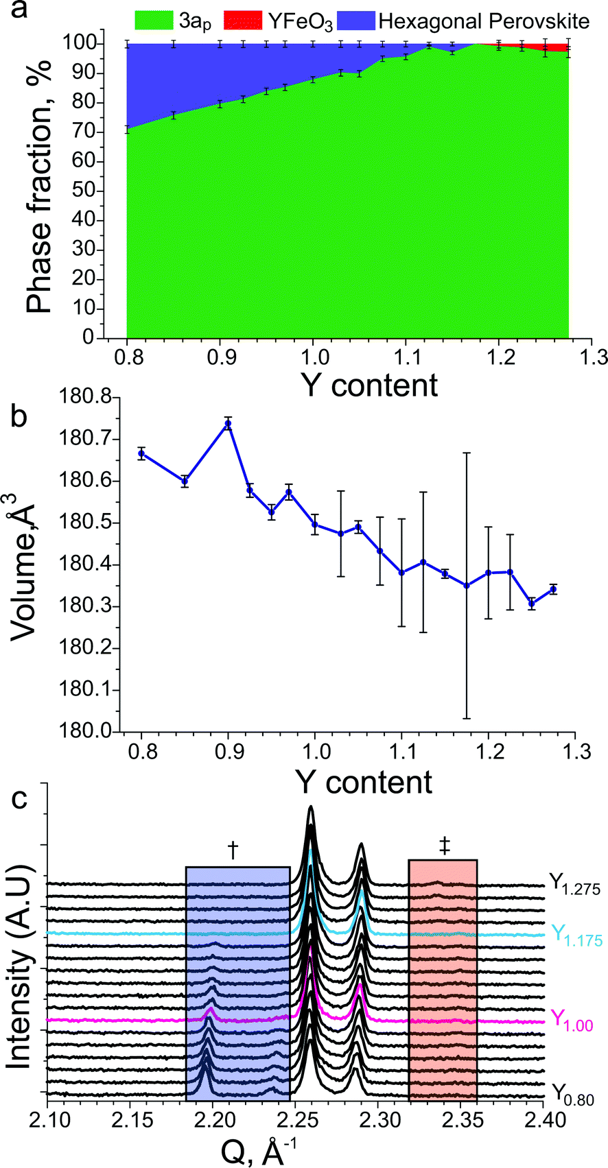 | ||
| Fig. 6 (a) Refined phase fractions in YyBa3−yFe2MnO8±δ samples as a function of the Y content, 3ap indicates the phase fraction of the desired phase, YFeO3 indicates the phase fraction of a perovskite similar to the reported YFeO3 material51 and hexagonal perovskite similar to the reported 10H BaMn0.4Fe0.6O3−δ material.52 (b) Refined unit cell volumes for YyBa3−yFe2MnO8 samples as a function of the Y content. (c) Cu Kα1 XRD patterns of YyBa3−yFe2MnO8±δ samples as a function of the Y content. The blue box labelled with † indicates the region where hexagonal perovskite reflections are observed and the red box marked with ‡ indicates the region where the main reflection for YFeO3 perovskite is observed. The stoichiometric YBa2Fe2MnO8±δ and phase-pure Y1.175Ba1.825Fe2MnO8±δ compositions have been plotted using red and blue lines respectively. | ||
The oxygen content at the optimised composition, Y1.175Ba1.825Fe2MnO8±δ, was analysed by iodometric titration. The determined oxygen content was O8.04(5), giving an average transition metal charge state of 2.97(3)+, assuming charge states of 3+ and 2+ on Y and Ba respectively. Mössbauer spectroscopy (Fig. 7c) of this sample shows the material to be magnetically ordered at room temperature. The spectrum showed the presence of two Fe3+ sites, which were refined as consistent with octahedral and square pyramidal geometries. In addition a small paramagnetic Fe4+ signal was observed, and modelled as disordered over both sites. The distribution of Fe atoms within the structure was refined as 80(1) % in square pyramidal geometry and 20(1) % in octahedral geometry. Using the assumption that the only other species on the same sites is Mn, and that there is a fixed ratio between square pyramidal and octahedral sites of 2:1, the distribution of Mn atoms is 40(1) % square pyramidal and 60(1)% octahedral.
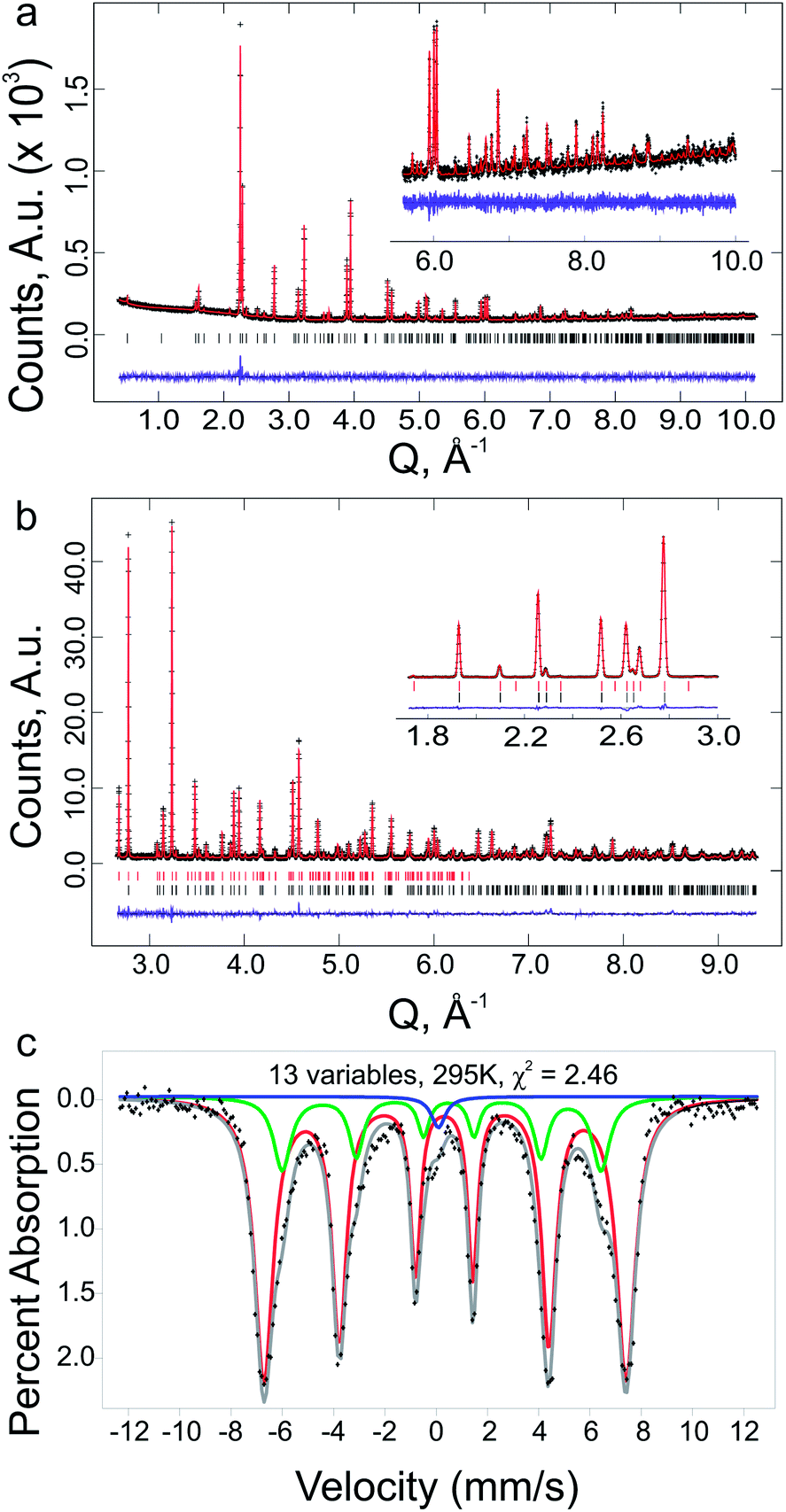 | ||
| Fig. 7 (a) Rietveld plot for Mo Kα1 PXRD data for phase pure Y1.175Ba1.825Fe2MnO8.04(5), with high Q range in-set. (b) Rietveld plot for HRPD 168° bank containing both nuclear and magnetic phases for phase pure Y1.175Ba1.825Fe2MnO8.04(5), with low Q range inset from HRPD 90° bank, black and red tick marks indicate the nuclear and magnetic hkl positions respectively. (c) Room temperature Mössbauer spectrum for phase pure Y1.175Ba1.825Fe2MnO8±δ, showing a fit to two Fe3+ environments for the refined as octahedral and square pyramidal geometries, and a singlet at Fe signal at ≈ 0 mm s−1, attributed to disordered Fe4+ in the system with an integrated area of 1.7(1) % of the total spectrum. | ||
Refinement of the 3ap unit cell as a function of the Y content over the YyBa3−yFe3O8 range, shows that there is a small variation in the unit cell volume (Fig. 6b). The variation in the cell volume implies that the structure should be accessible over a range of compositions; however, in our studies we only access the structure phase pure at one specific composition. This suggests that variation of the Fe:Mn ratio is also required at each Y:Ba ratio in order to synthesise the phase pure structure over a range of compositions, this was not attempted within this work as the Fe:Mn ratio was the focus of the DFT investigation, and the appropriate Y:Ba ratio was determined for the Fe:Mn ratio studied.
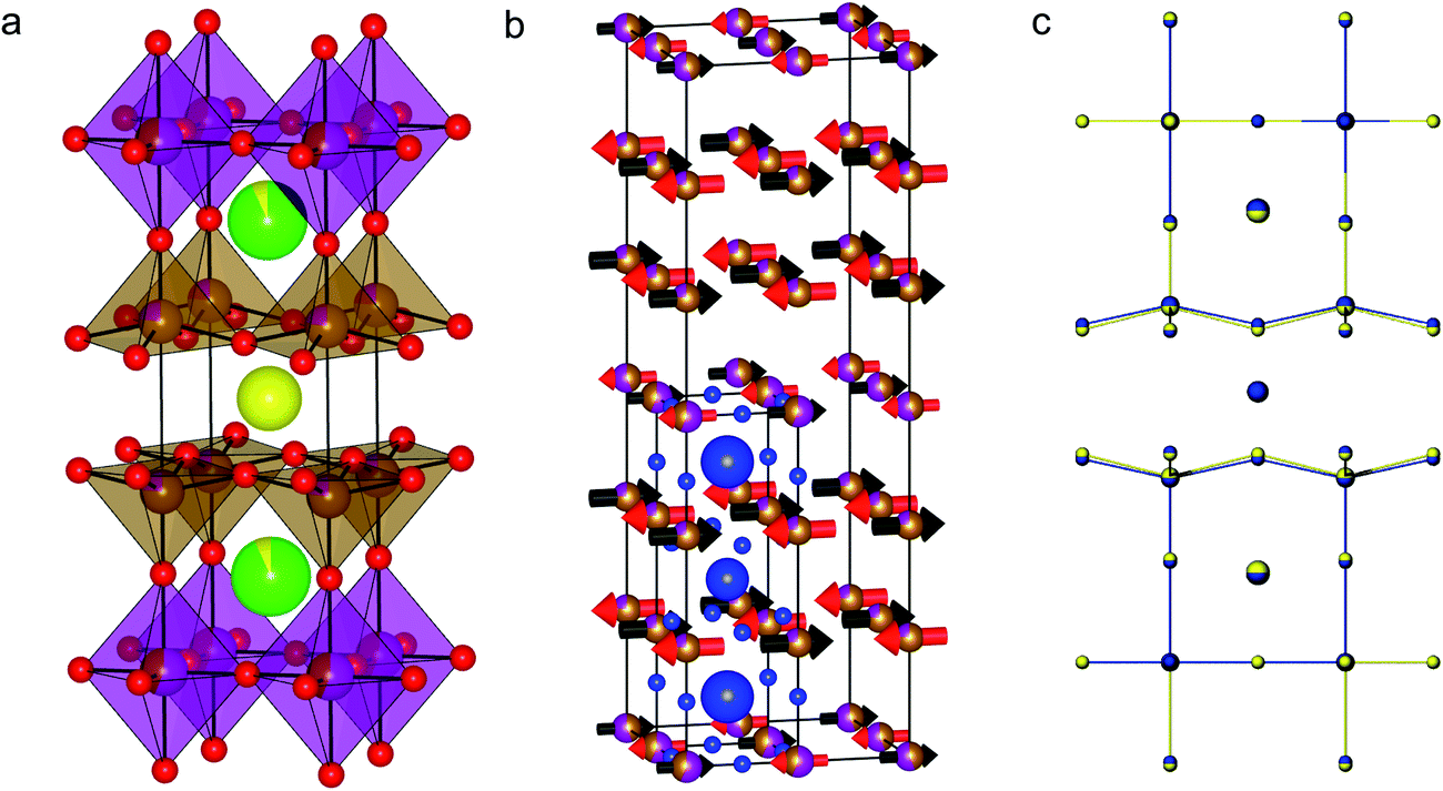
The results of DFT calculations were used as the basis for the structural refinement of Y1.175Ba1.825Fe2MnO8.04(5). The symmetry of the calculated YBa2Fe2MnO8 structure with octahedrally coordinated Mn atoms was determined using the FINDSYM code53 (version 3.2.3, with the tolerance set to 0.1 Å). The highest symmetry space group was determined to be tetragonal P4/mmm (Fig. 8a) in a unit cell where a = b = 3.91603 and c = 12.19815 Å. In order to be consistent with reported structures for the undoped material the origin of the unit cell was set to be at the octahedral B-site. The observed B-site occupancies from Mössbauer spectroscopy were used as the starting model for B-site ordering within the structure.
 | ||
| Fig. 8 (a) The refined nuclear structure of Y1.175Ba1.825Fe2MnO8.04(5) and (b) the refined magnetic structure. For clarity the atoms from the nuclear unit cell are overlaid in blue. (c) The observed Y1.175Ba1.825Fe2MnO8.04(5) structure (blue) overlaid with the DFT predicted cell (yellow). Note that the unit cell sizes have been normalised to the observed cell for clarity in observing the similarity between the observed and predicted atomic coordinates. | ||
For the Rietveld refinement of Y1.175Ba1.825Fe2MnO8.04(5), the structure was entered into GSAS64,65 as separate nuclear (PXRD and NPD) and magnetic (NPD only) phases. Following earlier refinements of the magnetic structure of YBa2Fe3O8,54 the magnetic cell was refined as a (2a, 2b, 2c) super-cell of the orthorhombic nuclear cell, in the orthorhombic Fmm′m′ magnetic space group configured in a G-type antiferromagnetic structure (see ESI† for further details). Constraints were setup between the two phases in order to keep the B-site atoms consistent (positions, occupancies and thermal parameters were constrained) and the unit cells and phase fractions of the two phases were fixed, so that the ratio of the lattice parameters and total number of B-site atoms was maintained between the nuclear and magnetic phases.
As the starting model for the structure refinement of Y1.175Ba1.825Fe2MnO8.04(5) was the atomic structure from the DFT model as described above, the composition was initially set close to the nominal value at Y1.16Ba1.84Fe2MnO8, with the additional Y inserted onto the Ba A-site. As the Rietveld refinement progressed, the composition was allowed to refine with the only restraint being that full occupancy was enforced at each metal site. During the Rietveld refinement the space group was changed to Pmmm to allow an orthorhombic distortion in the lattice parameters to improve the fit of broader reflections with hkl values where h ≠ k. The refined orthorhombic distortion is small with a strain (a − b)/(a + b) of 0.04%, and is presumably related to spin–orbit coupling which is not included in the current DFT calculations. The final Rietveld plots can be found in Fig. 7a and b, the resulting structure is shown in Fig. 8b and the results of the refinements are given in Tables 1 and 2, the reduced χ2 was 4.46 for 72 variables.
| Parameter | Rietveld | DFT | |
|---|---|---|---|
| a Total refined composition: Y1.14(1)Ba1.86(1)Fe1.961(4)Mn1.039(1)O8, formula weight = 651.37 g mol−1, formula units per cell = 1. | |||
| a (Å) | 3.88407(5) | 3.91603 | |
| b (Å) | 3.88125(5) | 3.91603 | |
| c (Å) | 11.98425(9) | 12.19815 | |
| Rietveld (Pmmm) | DFT (P4/mmm) | ||||||
|---|---|---|---|---|---|---|---|
| Site | Position | Composition | U iso (Å2) | Multiplicity | Position | Composition | Multiplicity |
| A1 | 0.5, 0.5, 0.5 | Y | 0.0127(2) | 1 | 0.5, 0.5, 0.5 | Y | 1 |
| A2 | 0.5, 0.5, 0.83558(7) | Ba0.929(5)Y0.071(5) | 0.0127(2) | 2 | 0.5, 0.5, 0.833890 | Ba | 2 |
| B1 | 0, 0, 0.66045(6) | Fe0.762(1)Mn0.238(1) | 0.013(1) | 2 | 0, 0, 0.656840 | Fe | 2 |
| B2 | 0, 0, 0 | Fe0.437(2)Mn0.563(2) | 0.0091(2) | 1 | 0, 0, 0 | Mn | 1 |
| O1 | 0.5, 0, 0.3757(1) | O | 0.0133(5) | 2 | 0, 0.5, 0.385130 | O | 4 |
| O2 | 0, 0.5, 0.3880(1) | O | 0.0175(6) | 2 | Equivalent to O1 | ||
| O3 | 0, 0, 0.81499(8) | O | U11 0.035(2) U22 0.024(1) U33 0.0224(6) | 2 | 0, 0, 0.809780 | O | 2 |
| O4 | 0.5, 0, 0 | O | 0.0067(6) | 1 | 0.5, 0, 0 | O | 2 |
| O5 | 0, 0.5, 0 | O | 0.0135(7) | 1 | Equivalent to O4 | ||
| Parameter | Rietveld | Relationship to nuclear | |
|---|---|---|---|
| a (Å) | 7.76814(9) | ×2 anuclear | |
| b (Å) | 7.76248(9) | ×2 bnuclear | |
| c (Å) | 23.9684(2) | ×2 cnuclear |
| Site | Parameter | Rietveld | Equivalent nuclear site (Table 1) |
|---|---|---|---|
| 1a | Position | 0, 0, 0 | B2 |
| Composition | Fe0.437(2)Mn0.563(2) | ||
| U iso (Å2) | 0.0091(2) | ||
| μ B | −2.81(4) | ||
| Multiplicity | 4 | ||
| 1b | Position | 0, 0, 0.5 | B2 |
| Composition | Fe0.437(2)Mn0.563(2) | ||
| U iso (Å2) | 0.0091(2) | ||
| μ B | +2.81(4) | ||
| Multiplicity | 4 | ||
| 2a | Position | 0, 0, 0.33025(3) | B1 z = znuclear/2 |
| Composition | Fe0.762(1)Mn0.238(1) | ||
| U iso (Å2) | 0.013(1) | ||
| μ B | −3.41(3) | ||
| Multiplicity | 8 | ||
| 2b | Position | 0, 0, 0.16975(3) | B1 z = ½ − znuclear/2 |
| Composition | Fe0.762(1)Mn0.238(1) | ||
| U iso (Å2) | 0.013(1) | ||
| μ B | +3.41(3) | ||
| Multiplicity | 8 |
Refinement of the oxygen content was trialled during the structure analysis. No vacancies were observed on the five oxygen positions and no extra oxygen within the structure could be found. This was trialled by placing an extra oxygen site in plane with the Y site (A1 in Table 1), previously reported as the O4 site in the undoped material.18 As no additional oxygen or any oxygen vacancies were found, the oxygen content was fixed to the nominal value of O8 in the final refinement, which is in good agreement with the oxygen content observed from iodometry (O8.04(5)).
During Rietveld refinement, the A-site ratios in Y1.175Ba1.825Fe2MnO8.04(5) changed from the starting values with small changes to the B-site ratio, to give a refined composition of Y1.14(1)Ba1.86(1)Fe1.961(4)Mn1.039(4)O8, a result close to the nominal composition of Y1.175Ba1.825Fe2MnO8.04(5). The composition of Y1.175Ba1.825Fe2MnO8.04(5) contains an excess of Y that occupies the A2 site together with Ba (Table 1). When trialled in the refinement there was no observed disorder on the A1 site which remained fully occupied by Y. The atomic coordinates of the refined structure show little deviation from those of the DFT structure (Fig. 8c and Table 1), with the exception of a small orthorhombic distortion and the z positions of O1 and O2 (Table 1). O1 and O2 are no longer related by symmetry due to the orthorhombic distortion away from the calculated tetragonal P4/mmm structure, and have different heights in the cell such that the basal planes of the square pyramids are slightly buckled.
Ordering between the two B-site geometries in the refined structure was observed to change little from the starting values of Fe0.8Mn0.2 (B1) and Fe0.4Mn0.6 (B2) for the square pyramidal and octahedral sites respectively, which were set to the refined Mössbauer occupancies. The refined site occupancies were Fe0.762(1)Mn0.238(1) for the square pyramidal site and Fe0.437(2)Mn0.563(2) for the octahedral site, a 4% difference from values refined using room temperature Mössbauer spectroscopy (Fig. 7c). Note that due to the large contrast in neutron scattering between Fe and Mn (coherent scattering lengths of 9.45 fm and −3.73 fm, respectively55), the refinement of the occupation of this site is reliable. The magnetic moments for the B-sites were refined to be 3.41(3) and 2.81(4) μB for the square pyramidal and octahedral sites respectively, consistent with the square pyramidal site hosting more Fe relative to the octahedral site.
Discussion
The initial DFT screening of potential doping onto the Fe site of YBa2Fe3O8 was successful in predicting a favourable doping species (Mn) and content (YBa2Fe2MnO8), which was previously unreported in the 3ap structure. We note, however, that considerable experimental work was still required to obtain a pure doped compound and characterize it, with slight differences in stoichiometry and structure compared to that predicted computationally.To reduce computational expense, DFT calculations were limited to stoichiometric compositions in which the average oxidation state on the B-site was restricted to 3+, or equivalently, the oxygen content was fixed to 8. Experimentally however, the sample composition and atmosphere used during synthesis were tuned to control the average transition metal charge state to near 3+ and to stabilise the 3ap phase relative to other competing phases containing Mn in a 4+ state. Successful experimental synthesis of pure 3ap Y1.175Ba1.825Fe2MnO8.04(5) required alteration of the A-site charge away from stoichiometry and control of oxygen partial pressure during synthesis using N2 gas, as synthesis in air and synthesis with lower average A-site charge state both resulted in the formation of Mn4+ containing species in preference to 3ap. In this case performing a calculation at the exact composition was not necessary to predict the initial doping success, however experimental refinement of the composition was still required to isolate the compound. Comparing the structure of the DFT predicted compound, YBa2Fe2MnO8, with the Rietveld refined structure of Y1.175Ba1.825Fe2MnO8.04(5), we find that the calculated unit cell volume is within 3.5% of experiment, with a similar agreement between the reported and calculated cell volumes for the undoped material.
One could envision calculating reaction energies for a number of non-stoichiometric compositions. However, for each composition larger super-cells and more configurations would be required in order to determine the most stable cation arrangement. Additional complexity is introduced by the necessity of modelling the inevitably disordered A-sites, as well as potentially disordered B-sites. Hence we suggest that a computational investigation of small changes in stoichiometry is unfeasible at present.
To quantify the level of ordering between Fe and Mn on the B-sites, we define the parameter Φ = (3f − 1)/2, where f is the fraction of Mn on the octahedral sites. DFT calculations predicted a complete segregation of Mn to the octahedral sites in YBa2Fe2MnO8 (Φ = 1), in a completely disordered system 1/3 of the octahedral sites would be occupied by Mn (Φ = 0), and experimentally the fraction of octahedral sites occupied by Mn was refined to 0.563(2) (Φ = 0.34). To model the expected extent of ordering at finite temperatures based on 0 K DFT energies, a statistical mechanics approach described in the ESI,†30 was applied to the six configurations used for the DFT calculations at the composition YBa2Fe2MnO8. When the occupations of the B-sites are estimated at the synthesis temperature of 1475 K, there is a preference for Mn in the octahedral site, though substantial mixing of Fe and Mn is predicted, with Φ = 0.57. At 300 K, however, the structure is predicted to be very close to fully ordered with Φ = 0.996. Under cooling during synthesis, cation motion will be frozen out at high temperatures, trapping the structure in a state with some site disorder due to configurational entropy. This explains the deviation of the refined value of Φ = 0.34 away from fully ordered Φ = 1, but shows that the 0 K DFT calculations had calculated the correct site preference for Mn within the structure.
A small, but significant difference between the calculated and experimental structure is the slight orthorhombic distortion of the refined nuclear structure. The tetragonal parent material, YBa2Fe3O8, is reported to become orthorhombic upon introduction of oxygen vacancies to form YBa2Fe3O8−δ (δ ≥ 0.14).21 It is possible that the orthorhombic distortion observed in Y1.175Ba1.825Fe2MnO8.04(5) is similarly due to oxygen vacancies, however we note that this is not supported by the results of iodometric titration or attempts to refine oxygen contents away from stoichiometry. An alternative explanation is that spin–orbit coupling of the antiferromagnetically ordered electronic spins, which necessarily have orthorhombic symmetry, has caused an orthorhombic distortion of the nuclear structure as reported for the mixed valence compound YBaFe2O5.56 In both cases, the orthorhombic distortion is accompanied by buckling of the basal planes of the square pyramidal sites, as observed here for Y1.175Ba1.825Fe2MnO8.04(5). Neither effect would be captured in the stoichiometric DFT calculations performed with collinear spin and neglecting spin–orbit interactions. The present experimental data are unable to distinguish between the two potential causes of this orthorhombic distortion.
The refined structure of Y1.175Ba1.825Fe2MnO8.04(5) shows that the unit cell distorts upon doping compared to YBa2Fe3O8 (ref. 18) by a 0.9% shortening of the a and b axes and a concurrent 1.4% lengthening of the c axis. This results in a 2.3% increase in the average c/a ratio upon doping, and a 0.5% reduction in cell volume. These changes in cell shape can be related to changes in the M–O bonding environments upon doping, seen in the comparison of the M–O bonds of Y1.175Ba1.825Fe2MnO8.04(5) and YBa2Fe3O8 (Table 3). As observed in the DFT calculations, experimentally the MOct – OAxial bond on the octahedral site is seen to lengthen on doping by 4.2% (0.094(3) Å), consistent with the expected Jahn–Teller distortion when accommodating Mn3+ in an octahedral site. The elongation of the unit cell upon doping is largely due to this Jahn–Teller distortion.
| Bond | YBa2Fe3O8 observed18 (Å) | Y1.175Ba1.825Fe2MnO8.04(5) observed (Å) | YBa2Fe3O8 DFT (Å) | YBa2Fe2MnO8 DFT (Å) |
|---|---|---|---|---|
| Moct – Oequatorial | 1.9590 | 1.94204(3) – O4, 1.94062(3) – O5, 1.94133(3) average | 1.9767 | 1.9580 |
| Moct – Oaxial | 2.1807(17) | 2.2173(10) – O3 | 2.2074 | 2.3203 |
| Msq.py – Oequatorial | 2.0198(4) | 1.9894(4) – O1, 2.0259(5) – O2, 2.0077(5) average | 2.0407 | 2.0240 |
| Msq.py – Oaxial | 1.8405(24) | 1.8513(12) – O3 | 1.8597 | 1.8649 |
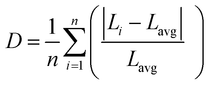
We used the methodology reported by Baur57 implemented in VESTA58 to further quantify the distortions of the polyhedra in the 3ap structure by calculation of a distortion parameter according to the following equation:
 | (4) |
| Geometry | YBa2Fe3O8 observed (literature)18 | Y1.175Ba1.825Fe2MnO8.04(5) observed (this work) | YBa2Fe3O8 DFT | YBa2Fe2MnO8 DFT |
|---|---|---|---|---|
| Square pyramid | 0.0226 | 0.0254 | 0.0289 | 0.026 (Octahedral configuration) |
| 0.020 (Square Pyramidal configuration) | ||||
| 0.027 (Mixed configuration) | ||||
| Octahedral | 0.0385 | 0.0603 | 0.0491 | 0.078 (Octahedral configuration) |
| 0.060 (Square Pyramidal configuration) | ||||
| 0.074 (Mixed configuration) |
Although this is the first reported mixed Fe/Mn compound with the 3ap structure, other perovskite based Fe/Mn oxides have been reported, and show similar site preferences. For example, the brownmillerite Ca2Fe2O5 has similarly distorted octahedral sites, with D = 0.045.24 Introduction of Mn into the compound to form Ca2Fe1.039(8)Mn0.962(8)O5 (ref. 27) leads to an increase in the distortion of the octahedral sites (D = 0.066), with Mn preferred in these sites. There are, however, many other examples of Mn3+ doping into perovskite based structures, in which the Mn3+ is coordinated in octahedral geometry,27,60 square pyramidal geometry28 or with B-site disorder.61,62 By the use of DFT we have been able to clearly predict the correct B-site ordering within a 3ap structure, even though precedents exist for all possible alternatives in known structures.
Conclusions
In summary, we have shown that it is possible to use DFT calculations to obtain reaction enthalpies to form complex oxides from binary oxides; we have then been able to use this method to predict a stable doping level in the YBa2Fe3O8 structure, with the Mn doping level of x = 1 and Mn atoms preferentially doping onto the already distorted octahedral site and increasing the level of distortion. We also have rationalised why doping becomes unfavourable when x = 2 and M = Mn; increasing the doping level above 1 forces a larger proportion of Mn atoms into the square pyramidal sites which in turn results in a less distorted octahedral geometry. These calculations have been able to successfully predict the approximate composition, B-site ordering (and distortion of B-sites, Fig. 8c) and accurate atomic coordinates of the doped structure of an oxide where the ordering is between two similar transition metals. The predicted material was then synthesised with only small deviations in the structure and composition.We have shown that using this methodology, we were able to predict compositions for which the formation of the 3ap structure is favourable or unfavourable, and that these results match subsequent experimental observations. We therefore conclude that the methodology presented here can be used as a powerful tool to guide the synthesis of new materials by chemical substitution and can be used for large and or complex oxides where the systems are too large or complex for existing methods.
Acknowledgements
This work was funded by the European Research Council (ERC Grant Agreement 227987 RLUCIM). We thank EPSRC for a studentship to C. Collins. We gratefully acknowledge ISIS and the STFC Rutherford Appleton Laboratory for provision of neutron diffraction facilities and Aziz Daoud-Aladine for assistance in using HRPD. Structural images were made using VESTA.58 MJR thanks the Royal Society for the award of a Research Professorship.References
- M. A. Pena and J. L. G. Fierro, Chem. Rev., 2001, 101, 1981–2017 CrossRef CAS PubMed.
- A. Aguadero, L. Fawcett, S. Taub, R. Woolley, K. T. Wu, N. Xu, J. A. Kilner and S. J. Skinner, J. Mater. Sci., 2012, 47, 3925–3948 CrossRef CAS.
- T. Minami, Semicond. Sci. Technol., 2005, 20, S35–S44 CrossRef CAS.
- J. P. Attfield, J. Mater. Chem., 2011, 21, 4756–4764 RSC.
- V. V. Shvartsman and D. C. Lupascu, J. Am. Ceram. Soc., 2012, 95, 1–26 CrossRef CAS.
- L. B. Kong, S. Li, T. S. Zhang, J. W. Zhai, F. Y. C. Boey and J. Ma, Prog. Mater. Sci., 2010, 55, 840–893 CrossRef CAS PubMed.
- J. W. Fergus, J. Eur. Ceram. Soc., 2012, 32, 525–540 CrossRef CAS PubMed.
- Y. L. Chen and S. F. Yang, Adv. Appl. Ceram., 2011, 110, 257–269 CrossRef CAS PubMed.
- R. C. Pullar, Prog. Mater. Sci., 2012, 57, 1191–1334 CrossRef CAS PubMed.
- J.-I. Jung, S. T. Misture and D. D. Edwards, Solid State Ionics, 2010, 181, 1287–1293 CrossRef CAS PubMed.
- J. Pena-Martinez, D. Marrero-Lopez, J. C. Ruiz-Morales, P. Nunez, C. Sanchez-Bautista, A. J. Dos Santos-Garcia and J. Canales-Vazquez, Int. J. Hydrogen Energy, 2009, 34, 9486–9495 CrossRef CAS PubMed.
- Z. P. Shao and S. M. Haile, Nature, 2004, 431, 170–173 CrossRef CAS PubMed.
- A. Yan, M. Yang, Z. Hou, Y. Dong and M. Cheng, J. Power Sources, 2008, 185, 76–84 CrossRef CAS PubMed.
- P. K. Nayak, J. Yang, J. Kim, S. Chung, J. Jeong, C. Lee and Y. Hong, J. Phys. D: Appl. Phys., 2009, 42, 035102 CrossRef.
- H. Agura, A. Suzuki, T. Matsushita, T. Aoki and M. Okuda, Thin Solid Films, 2003, 445, 263–267 CrossRef CAS.
- R. E. Treharne, K. Hutchings, D. A. Lamb, S. J. C. Irvine, D. Lane and K. Durose, J. Phys. D: Appl. Phys., 2012, 45, 335102 CrossRef.
- R. J. Cava, A. W. Hewat, E. A. Hewat, B. Batlogg, M. Marezio, K. M. Rabe, J. J. Krajewski, W. F. Peck Jr and L. W. Rupp Jr, Physica C, 1990, 165, 419–433 CrossRef CAS.
- P. Karen, E. Suard and F. Fauth, Inorg. Chem., 2005, 44, 8170–8172 CrossRef CAS PubMed.
- Q. Z. Huang, V. L. Karen, A. Santoro, A. Kjekshus, J. Lindén, T. Pietari and P. Karen, J. Solid State Chem., 2003, 172, 73–80 CrossRef CAS.
- P. Karen and A. Kjekshus, J. Solid State Chem., 1994, 112, 73–77 CrossRef CAS.
- P. Karen, A. Kjekshus, Q. Huang, V. L. Karen, J. W. Lynn, N. Rosov, I. Natali Sora and A. Santoro, J. Solid State Chem., 2003, 174, 87–95 CrossRef CAS.
- I. Felner, I. Nowik, U. Yaron, O. Cohen, E. R. Bauminger, T. Kroener and G. Czjzek, Phys. Rev. B: Condens. Matter Mater. Phys., 1993, 48, 16040–16046 CrossRef CAS.
- Q. Huang, P. Karen, V. L. Karen, A. Kjekshus, J. W. Lynn, A. D. Mighell, N. Rosov and A. Santoro, Phys. Rev. B: Condens. Matter Mater. Phys., 1992, 45, 9611–9619 CrossRef CAS.
- A. L. Shaula, Y. V. Pivak, J. C. Waerenborgh, P. Gaczyñski, A. A. Yaremchenko and V. V. Kharton, Solid State Ionics, 2006, 177, 2923–2930 CrossRef CAS PubMed.
- A. Demont, M. S. Dyer, R. Sayers, M. F. Thomas, M. Tsiamtsouri, H. N. Niu, G. R. Darling, A. Daoud-Aladine, J. B. Claridge and M. J. Rosseinsky, Chem. Mater., 2010, 22, 6598–6615 CrossRef CAS.
- F. Ramezanipour, J. E. Greedan, L. M. D. Cranswick, V. O. Garlea, R. L. Donaberger and J. Siewenie, J. Am. Chem. Soc., 2012, 134, 3215–3227 CrossRef CAS PubMed.
- F. Ramezanipour, B. Cowie, S. Derakhshan, J. E. Greedan and L. M. D. Cranswick, J. Solid State Chem., 2009, 182, 153–159 CrossRef CAS PubMed.
- F. Millange, E. Suard, V. Caignaert and B. Raveau, Mater. Res. Bull., 1999, 34, 1–9 CrossRef CAS.
- G. Hautier, C. Fischer, V. Ehrlacher, A. Jain and G. Ceder, Inorg. Chem., 2011, 50, 656–663 CrossRef CAS PubMed.
- R. Grau-Crespo, S. Hamad, C. R. A. Catlow and N. H. de Leeuw, J. Phys.: Condens. Matter, 2007, 19, 256201 CrossRef.
- B. J. Morgan and G. W. Watson, J. Phys. Chem. Lett., 2011, 2, 1657–1661 CrossRef CAS.
- S. Benny, R. Grau-Crespo and N. H. de Leeuw, Phys. Chem. Chem. Phys., 2009, 11, 808–815 RSC.
- J. J. Adkin and M. A. Hayward, J. Solid State Chem., 2006, 179, 70–76 CrossRef CAS PubMed.
- Q. Wang, R. Grau-Crespo and N. H. de Leeuw, J. Phys. Chem. B, 2011, 115, 13854–13861 CrossRef CAS PubMed.
- Q. Wang and N. H. de Leeuw, Mineral. Mag., 2008, 72, 525–529 CrossRef CAS PubMed.
- Y. Seminovski, P. Palacios, P. Wahnon and R. Grau-Crespo, Appl. Phys. Lett., 2012, 100, 102112 CrossRef PubMed.
- D. O. Scanlon and A. Walsh, Appl. Phys. Lett., 2012, 100, 251911 CrossRef PubMed.
- B. Saha, J. Acharya, T. D. Sands and U. V. Waghmare, J. Appl. Phys., 2010, 107, 033715 CrossRef PubMed.
- D. J. Fredeman, P. H. Tobash, M. A. Torrez, J. D. Thompson, E. D. Bauer, F. Ronning, W. W. Tipton, S. P. Rudin and R. G. Hennig, Phys. Rev. B: Condens. Matter Mater. Phys., 2011, 83, 224102 CrossRef.
- M. Pishahang, C. E. Mohn, S. Stolen and E. Bakken, RSC Adv., 2012, 2, 10667–10672 RSC.
- Y. L. Lee, J. Kleis, J. Rossmeisl and D. Morgan, Phys. Rev. B: Condens. Matter Mater. Phys., 2009, 80, 224101 CrossRef.
- M. Regulski, R. Przeniosło, I. Sosnowska, D. Hohlwein and R. Schneider, J. Alloys Compd., 2004, 362, 236–240 CrossRef CAS.
- D. Rodic, V. Spasojevic, V. Kusigerski, R. Tellgren and H. Rundlof, Phys. Status Solidi B, 2000, 218, 527–536 CrossRef CAS.
- M. Catti, G. Valerio and R. Dovesi, Phys. Rev. B: Condens. Matter Mater. Phys., 1995, 51, 7441–7450 CrossRef CAS.
- M. Faucher and J. Pannetier, Acta Crystallogr., Sect. B: Struct. Sci., 1980, 36, 3209–3211 CrossRef.
- L. G. Liu, J. Appl. Phys., 1971, 42, 3702–3704 CrossRef CAS PubMed.
- W. L. Roth, J. Phys. Chem. Solids, 1964, 25, 1–10 CrossRef CAS.
- R. Miloua, F. Miloua, A. Arbaoui, Z. Kebbab and N. Benramdane, Solid State Commun., 2007, 144, 5–9 CrossRef CAS PubMed.
- I. Felner and J. Gersten, Czech J. Phys., 1996, 46, 1421–1422 CrossRef CAS.
- D. A. Kudryavtsev, B. V. Mill, N. F. Vedernikov and I. S. Shaplygin, Inorg. Mater., 1992, 28, 943–946 Search PubMed.
- D. DuBoulay, E. N. Maslen, V. A. Streltsov and N. Ishizawa, Acta Crystallogr., Sect. B: Struct. Sci., 1995, 51, 921–929 CrossRef.
- L. Miranda, K. Boulahya, A. Varela, J. M. Gonzalez-Calbet, M. Parras, M. Hernando, M. T. Fernandez-Diaz, A. Feteira and D. C. Sinclair, Chem. Mater., 2007, 19, 3425–3432 CrossRef CAS.
- H. T. Stokes and D. M. Hatch, J. Appl. Crystallogr., 2005, 38, 237–238 CrossRef CAS.
- J. Cui, Q. Huang and B. H. Toby, Powder Diffr., 2006, 21, 71–79 CrossRef CAS.
- V. F. Sears, J. Neutron Res., 1992, 3, 26–37 CrossRef.
- P. M. Woodward and P. Karen, Inorg. Chem., 2003, 42, 1121–1129 CrossRef CAS PubMed.
- W. H. Baur, Acta Crystallogr., Sect. B: Struct. Sci., 1974, 30, 1195–1215 CrossRef CAS.
- K. Momma and F. Izumi, J. Appl. Crystallogr., 2011, 44, 1272–1276 CrossRef CAS.
- H. Saalfeld, Z. Kristallogr., Mineral. Petrogr., Abt. A, 1964, 120, 342–348 CAS.
- A. Munoz, J. A. Alonso, M. J. Martinez-Lope and J. L. Martinez, Chem. Mater., 2004, 16, 4087–4094 CrossRef CAS.
- N. Kallel, S. Ben Abdelkhalek, S. Kallel, O. Pena and M. Oumezzine, J. Alloys Compd., 2010, 501, 30–36 CrossRef CAS PubMed.
- J. H. Shin, M. S. Song and J. Y. Lee, J. Electroceram., 2006, 17, 205–209 CrossRef CAS.
- E. García-Matres, J. L. Martínez, J. Rodríguez-Carvajal, J. A. Alonso, A. Salinas-Sánchez and R. Saez-Puche, J. Solid State Chem., 1993, 103, 322–333 CrossRef.
- B. H. Toby, J. Appl. Crystallogr., 2001, 34, 210–213 CrossRef CAS.
- A. C. Larson and R. B. Von Dreele, General Structure Analysis System (GSAS), 1994 Search PubMed.
Footnote |
| † Electronic supplementary information (ESI) available. See DOI: 10.1039/c3sc52734d |
| This journal is © The Royal Society of Chemistry 2014 |