Electrode materials for aqueous asymmetric supercapacitors
Faxing Wang, Shiying Xiao, Yuyang Hou, Chenglin Hu, Lili Liu and Yuping Wu*
New Energy and Materials Laboratory (NEML), Department of Chemistry & Shanghai Key Laboratory of Molecular Catalysis and Innovative Materials, Fudan University, Shanghai 200433, China. E-mail: wuyp@fudan.edu.cn; Fax: +86-21-5566 4223; Tel: +86-21-5566 4223
First published on 16th April 2013
Abstract
An asymmetric supercapacitor (ASC) is a supercapacitor based on two different electrode materials. One electrode is based on redox (Faradic) reactions with or without non-faradic reactions, and the other one is mostly based on electric double-layer (non-Faradic or electrostatic) absorption/desportion. Aqueous electrolytes have higher ionic conductivity, larger capacitance and better safety than the organic electrolytes. Herein, some key electrode materials for aqueous ASCs are primarily reviewed, which provide a new direction for power sources to have higher energy density at high power densities, compared with traditional capacitors. Their negative electrode materials include carbonaceous materials (porous carbons, carbon nanotubes and graphene), oxides (V2O5 and MoO3) and their composites, and their positive electrode materials include carbonaceous materials, oxides (RuO2, MnO2, MoO3, V2O5, PbO2, Co3O4), Ni(OH)2, intercalation compounds (LiCoO2, LiMn2O4, Li[NiCoMn]1/3O2, NaMnO2 and KMnO2). We describe the latest work on these electrode materials, and a particular focus is directed to the fabrication and electrochemical performance of various nanostructured electrode materials and some assembled ASCs. Finally, the future trends and prospects on advanced energy storage materials are suggested.
 Yuping Wu | Dr Yuping Wu is a professor at Fudan University, Shanghai, China. Since 1994, he has published over 190 peer-reviewed papers, written five monographs whose sales are above 23000 copies and 4 chapters, translated one book, got 19 issued patents. H-index is 32. His research has led to the creation of three companies on anode materials, cathode materials and power lithium ion batteries, respectively. His research is mainly focused on lithium ion batteries, supercapacitors, other new energy storage and conversion systems and solar hydrogen. |
1. Introduction
Recently, there has been an increasing demand for environmentally friendly and high-performance supercapacitors, which have found important applications in rapidly expanding markets, especially in electric vehicles (EVs) and smart grids. The EV is a promising “zero-emission” vehicle, which is expected to significantly contribute to solving the problems of global warming and environmental pollution. Supercapacitors can be coupled with batteries and fuel cells to provide peak power in all-electric vehicles and replace batteries for memory back-up, which makes them probably one of the most important energy storage devices. Smart grids are also very important to increase the power efficiency and utilize renewable energies.1Currently, supercapacitors have several types, which are briefly listed in Table 1, and they can store hundreds or thousands of times more charge than the conventional capacitors. However, their energy density is still lower compared with batteries and fuel cells. Therefore, one of the most critical aspects in the development of hybrid supercapacitors (HSCs) is to enhance their energy density while retaining their intrinsic high specific power. Many different systems including different materials have been investigated extensively; however, so far there is no unambiguous definition of HSC. These kinds of HSC systems were firstly named “asymmetric supercapacitors”.2a,2b The term “hybrid capacitor” was first introduced and trademarked by Evans Capacitor Company.2c Here, hybrid supercapacitors (HSCs) include composite symmetric supercapacitors, battery–supercapacitor hybrids and asymmetric supercapacitors (ASCs). ASCs usually consist of two different electrodes. During charge and discharge processes, one electrode should take place redox (Faradic) reactions with or without non-faradic reactions, and the other one mostly taking place is electric double-layer (EDL) (non-Faradic or electrostatic) absorption/desportion.2d The structure of ASCs can be schematically illustrated in Fig. 1.
 | ||
| Fig. 1 Schematic illustration of ASCs. | ||
| Types | Mechanisms | Materials | Merits | Shortcomings | |
|---|---|---|---|---|---|
| EDLCs | Charge separation at the electrode–electrolyte interface | Carbon materials | High power density, and good cycling behaviors | Low energy density, and low working voltage | |
| Pseudo-capacitors | Reversible surface Faradic redox reactions | Transition metal oxides, conducting polymers | High capacitance and energy density | Poor cycling behavior, and low working voltage | |
| Composite symmetric | Two electrodes are the same and present electric double-layer absorption/desorption and Faradic redox reactions. | Composites of pseudo-capacitive materials with carbon materials | Relatively high energy and power densities | Low working voltage | |
| HSCs | ASCs | Redox reaction(s) for one electrode and electric double-layer absorption/desorption for the other electrode | Porous carbons, graphene, oxides, conductive polymers, lithium intercalation compounds | Relatively high energy and power densities, and good cycling | Almost every performance is at the intermediate level |
| Battery-typed | Redox reactions for both electrodes. | Lithium intercalation compounds | High energy density and working voltage | Poor cycling behaviors, low power density | |
In terms of ASCs, there are two important parameters: energy density (E) and power density (P). The expressions of both parameters are shown as eqn (1) and (2).3
 | (1) |
 | (2) |
Where V is working voltage, C the specific capacitance of the electrode materials and R the internal resistance.
In order to achieve large E and P, both C and V are needed to increase. The working voltage, V, is mainly limited by electrolytes, and thus ASCs are mainly classified into two types based on electrolytes: aqueous and nonaqueous.4a,4b At present, most commercial products use organic electrolytes, which offer a wider electrochemical window. Although the working voltage of organic electrolytes can be up to 3V,4c they are associated with safety risks because of the flammability of the organic electrolytes and improper use such as overcharging or short-circuiting. Their practical energy density is not high, and most of them are below 5 Wh kg−1. The main reason is that C is not large enough due to the large sizes of the organic molecules. In fact, aqueous electrolytes have significant inherent advantages over organic electrolytes:
• The cost of the aqueous electrolyte is low because the expensive salts can be replaced by cheap ones.
• The assembling process is easy, and high-cost devices and assembly techniques are not required.
• It is inherently safe by avoiding the use of flammable organic electrolytes.
• The ionic conductivity of aqueous electrolytes is high, about two orders of magnitudes higher than that of organic electrolytes,4d which ensures high rate capability and thus high specific power. In aqueous electrolytes, the bare electrode is exposed to the electrolyte in the absence of surface layer and the charge transfer occurs easily across the electrolyte/electrode interface without the impeding effect of the surface layer.
• Water is an ideal electrolyte solvent, in that the decomposition products, hydrogen and oxygen, will not contaminate the electrolyte. In addition, water can render the supercapacitors tolerant to overcharging by producing hydrogen and oxygen at the negative and positive electrodes, respectively.4e
• Hydrated ions are much smaller than those ions solvated by organic electrolytes, and their capacitance is much larger than for the organic electrolytes.
• As a result, even if the working voltage of aqueous electrolyte is low, it is of great promise for the aqueous ASCs to achieve higher energy and power densities.2,5
In this review, our main target is aqueous ASCs, and some characteristics are summarized in Table 2. The key to achieving high energy and power densities for aqueous ASCs is the development of appropriate electrode materials. Herein, a brief summary of the latest progress concerning their electrode materials is provided. A particular focus is directed to the preparation and electrochemical performance of various nanostructured electrode materials, which are advantageous to achieve high power density.5a Current challenges and future strategies of ASCs are also discussed.
| Negative materials | Positive materials | Electrolytes | Working voltage | Rate behavior | Cycling performancea | Ref. |
|---|---|---|---|---|---|---|
| a The numbers indicate the cycling number and capacitance retention in the brackets, respectively. | ||||||
| AC | V2O5 | 0.5 mol l−1 K2SO4 | 0–1.8 V | — | 100 | 6a |
| PPy@V2O5 | AC | 0.5 mol l−1 K2SO4 | 0–1.8 V | — | 10![[thin space (1/6-em)]](https://www.rsc.org/images/entities/char_2009.gif) 000(>95%) 000(>95%) | 6b |
| MoO3 nanoplates | AC | 0.5 mol l−1 Li2SO4 | 0–1.8 V | 2 A g−1 | 400 | 6c |
| AC | RuO2@TiO2 nanotube | 1 mol l−1 KOH | 0–1.4 V | 0.12 A cm−2 | 1000(>90%) | 6d |
| AC | MnO2 | 0.1 mol l−1 K2SO4 (without O2) | 0–2 V | 40 mA cm−2 | 195000 | 7a |
| AC | MnO2@AC | 0.5 mol l−1 Na2SO4 | 0–1.8 V | 12.74 mA cm−2 | 1500 | 7b |
| AC | MnO2 nanorod | 0.5 mol l−1 K2SO4 | 0–1.8 V | 10 C | 23000 (100%) | 7c |
| AC | Nanowires MnO2 @MWCNTs | 0.5 mol l−1 Li2SO4 | 0–1.8 V | 1 A g−1 | 13000 | 7d |
| SWCNTs | MnO2@graphene | 0.5 mol l−1 Na2SO4 | 0–1.5 V | 2.2 A g−1 | 5000 | 8a |
| AC nanofibers | MnO2@graphene | 1 mol l−1 Na2SO4 | 0–1.8 V | 1.2 A g−1 | 1000 | 8b |
| Graphene | Nanowires MnO2@graphene | 1 mol l−1 Na2SO4 | 0–2 V | 5 A g−1 | 1000 | 8c |
| AC | PbO2 | 5.3 mol l−1 H2SO4 | 0.8–1.8 V | 0.8 A g−1 | 4500 (90%) | 8d |
| AC | PbO2 nanowires | 0.1 mol l−1 CH3SO3H + 0.1mol l−1 Pb(NO3)2 + 4 mol l−1 NaNO3 | 0–1.7 V | 40C | 5000 (100%) | 9a |
| AC | Ni(OH)2@CNTs | 6 mol l−1 KOH | 0–1.6 V | 0.5 A g−1 | — | 9b |
| AC | LiCoO2 nanoparticles | 0.5 mol l−1 Li2SO4 | 0–1.8 V | 10 A g−1 | 40 (100%) | 9c |
| AC | LiMn2O4 nanorods | 0.5 mol l−1 Li2SO4 | 0–1.8 V | 10 A g−1 | 1200 (>94%) | 9d |
| AC | LiMn2O4 nanochains | 0.5 mol l−1 Li2SO4 | 0–1.8 V | 10 A g−1 | 200 (100%) | 10a |
| AC | Porous LiMn2O4 | 0.5 mol l−1 Li2SO4 | 0–1.8 V | 90C | 10000 (93%) | 10b |
| AC | NaMnO2 | 0.5 mol l−1 Na2SO4 | 0–1.9 V | 120 C | 10000 (100%) | 10c |
| AC | K0.27MnO2 | 0.5 mol l−1 K2SO4 | 0–1.8 V | 25 C | 10000 (100%) | 10d |
2. Negative electrode materials for asymmetric supercapacitors
Negative electrode materials, which are sometime called anode materials, include carbonaceous materials (porous carbons, carbon nanotubes (CNTs) and graphene), oxides (V2O5, MoO3), their composites and other materials.2.1 Carbonaceous materials
Carbonaceous materials include porous carbons, carbon nanotubes (CNTs) and graphene, and their action mechanism is as eqn (3). Of course, they can also be used as positive electrode materials for ASCs. However, their action mechanism is different. As to other carbons such as carbon xerogels and carbon nanocages, they are just different in shape or morphology. Their action as negative electrode materials for ASCs is principally the same and they will not be specifically discussed here.5a,5b| Carbon + C+ + e− ↔ Carbon/C | (3) |
Where C+ and/represent cation and interface, respectively.
There are two methods to prepare ACs: physical and chemical activation. The former involves gasification of the carbon produced from carbonization with an oxidizing gas such as air, CO2 and water vapor at elevated temperatures. In the case of the latter, carbonization and activation are carried out by thermal decomposition of the precursor impregnated with a chemical activating agent, such as ZnCl2, KOH, K2CO3, HNO3 or H3PO4. Recently, some processes including laser ablation, electrical arc, chemical vapor decomposition (CVD) and nanocasting, which do not include activation processes, can also be used to prepare ACs.5a A variety of precursors are used for producing ACs such as charcoals (i.e. woods and coconuts), resins, petroleum coke, pitch and biomasses including waste paper.6e
Since the action mechanism for capacitance is mainly due to absorption/desorption, the specific surface area, porosity and functional groups of ACs are important factors to achieve high energy density, which are dependent on the nature of precursor, activating agent, and condition of the activation process. For instance, the solid product obtained from a specific raw material containing dominantly aromatic compounds (such as biomass-derived tar), is characterized by a dense structure and weak reactivity towards steam activation. On the contrary, the final carbon material prepared from a furfural precursor is less dense and more reactive, due to the insertion of oxygen in the carbon skeleton that favors the formation of pores during the activation process. The pores including micro-, meso-, and macro-pores in the ACs are randomly distributed.
In the case of NPCs, most are prepared by template methods so that the porosity and pore size can be tailored. For example, metal–organic frameworks (MOFs) such as Zn4O(OOCC6H4COO)3), silicas such as SBA-15, zeolites and oxides such as MgO can be used as templates. The pore size is dependent on the templates and the porosity is on the amount of the templates.5a,6f
Of course, the surface of carbonaceous materials can be modified by some methods such as oxidation and plasma treatment to introduce functional groups.
When a potential is applied to a porous carbon electrode, oppositely charged ions are absorbed on its pore surfaces and electric double-layers are formed, thereby electricity being stored, and they can be used for the non-Faradic side of ASCs.11 Acid, alkaline and neutral solutions can be used as electrolytes (Fig. 2). Cyclic voltammograms (CVs) are typically rectangular and time-potential curves are linear. However, due to the existence of some surface functional groups such as –C–OH, –C![[double bond, length as m-dash]](https://www.rsc.org/images/entities/char_e001.gif) O, –COOH, which can take place in the redox reactions, as shown in eqn (4)–(6), to produce pseudo capacitance, the CV curves deviate from rectangular—as shown in Fig. 2.
O, –COOH, which can take place in the redox reactions, as shown in eqn (4)–(6), to produce pseudo capacitance, the CV curves deviate from rectangular—as shown in Fig. 2.
| –C–OH ↔ –CO + H+ + e− | (4) |
| –COOH ↔ –COO + H+ + e− | (5) |
| –CO + e− ↔ –C–O− | (6) |
 | ||
| Fig. 2 CV curves of AC as negative electrodes in different aqueous electrolytes: (a), (b) (modified from ref. 12b), (c) 0.5 mol l−1 Li2SO4, Na2SO4 and K2SO4 solutions and (d) the change of capacitance with the scan rate in different aqueous electrolytes (modified from ref. 13). Note: Fig. 2b also shows that AC can also be positive electrodes. | ||
However, as the amount of the functional groups on the surface is low, it could not present strong redox peaks on CV curves. During the modification, oxidation for too long a timescale is detrimental for carbon materials since it could reduce the surface area and electronic conductivity of the carbons, and impair their capacitive performance.
The specific capacitance of ACs is determined by both the ratio of edge/basal orientation and the nature of the functional group on the surface.12a A higher percentage of edge orientation results in the higher double-layer capacitance and favors stronger bonding of surface functional groups.
Considering the pore sizes, their influence on capacitance is closely related to electrolytes. Pores larger than 0.5 nm are generally available for the electroadsorption of simple hydrated ions in aqueous solutions. The optimal pore size range for double layer capacitance of NPCs in aqueous H2SO4 is between 0.8 and 2.0 nm. It is suggested that the adsorption of desolvated cations by contacting walls of small micropores seems to be more possible.5a
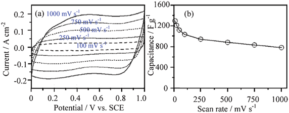
In the case of the same AC material in acid (1 mol l−1 H2SO4) or alkaline (6 mol l−1 KOH) solutions, different capacitances will be achieved.12b In neutral solutions, the ion size will also present different behavior at different current or power densities. For example, in 0.5 mol l−1 Li2SO4, Na2SO4 and K2SO4 aqueous electrolytes,13 the rate behavior of the AC improves in the order of Li2SO4 < Na2SO4 < K2SO4. This can be attributed to the different hydrated ionic radius of Li+ (3.82 Å), Na+ (3.58 Å) and K+ (3.31 Å) contributing to their different charge densities and their different migration speeds.14 The hydrated ionic radius of K+ is the smallest and its ionic conductivity is the highest, consequently its access to the inner pores of AC is much easier than Na+ and Li+, and the relaxation time for the migration of the hydrated K+ is the shortest at the high scan rate. In addition, the equivalent series resistance (ESR) values for the three electrolytes decrease in the order of Li2SO4 > Na2SO4 > K2SO4. As a result, K2SO4-based electrolyte exhibits the largest capacitance at the high scan rates. At the low scan rate, the capacity is mainly determined by the size of un-hydrated cations, which decreases in the order of Li+ > Na+ > K+ (Fig. 2d).13
CNTs can be doped by nitrogen and oxygen like disordered carbons.16e Together with other kinds of carbon materials, composites such as core-shell structures can be prepared.17a The core and the sheath can be composed of aligned CNTs and network-like nitrogen-doped CNTs, respectively. These composite fibers are flexible and weavable with excellent mechanical and electronic properties, which make them very promising as a family of new and high-performance fiber-shaped negative electrodes for ASCs. Interestingly, macroscopic Ni-microfiber-supported CNT aerogels can also be developed with a better electronic conductive network.17b
The capacitive behavior of CNTs is similar to that of AC. In the case of the hetero-atoms doped CNTs, it exhibits pseudo-capacitance through a Faradic reaction in the framework or as functional groups on the surface,17a which is similar to the doping of N in carbon for anode materials of lithium ion batteries.16e Interestingly, macroscopic Ni-microfiber-supported CNT aerogels show high specific capacitance (up to 359 F g−1 at the scan rate of 1 mV s−1) in a 5.0 mol l−1 KOH aqueous electrolyte solution due to the excellent ion diffusivity, high electronic conductivity and large mesopore surface area of this composite electrodes, in which the Ni microfiber network serves as current collector, CNTs as nano conducting wire and carbon nanotube aerogels as ion storage reservoir. The specific capacitance of the composite based on CNTs increases with the amount of carbon aerogel. In addition, the cycling performance is also satisfactory.17b
In both single and multi-walled CNTs, the electronic transport occurs over long tube ranges without electronic scattering and the network of large external small pores formed by the entanglement of the CNTs allows for fast solvated ion diffusion during charge and discharge processes. This property makes them successful at carrying high densities of currents without energy dissipation.17c As a result, in most cases CNTs are often used in the form of composites, and their preparation and electrochemical performance in aqueous electrolytes will be expounded in the corresponding sections.
CNTs exhibit properties amenable to capacitive energy storage with unique tubular porous structures and superior electronic properties, fast ion and electron transportation. However, the production costs of CNT-based supercapacitors still cannot meet acceptable performance18 and great efforts are still needed on developing novel carbon-based supercapacitor electrode materials with an overall high performance.19
Graphene can be prepared by several kinds of methods: exfoliation and cleavage of natural graphite, chemical vapor deposition (CVD) and plasma enhanced CVD (PE-CVD), electric arc discharge, epitaxial growth on electrically insulating surfaces such as silicon carbide (SiC), un-zipping of carbon nanotubes (CNTs), solution-based reduction of graphite oxides and so on.23 Chemical synthesis of graphene using graphite, graphite oxide (GO) or other graphite derivatives as starting materials can not only be scalable but also provide graphene with processibility and new functions.24 Usually, GO is firstly prepared in large quantities from graphite by the Hummers method using KMnO4 and sulfuric acid.25 Because of their COO− groups, the graphene oxide product can be purified by centrifugation and dialysis to remove aggregates and various inorganic impurities such as metal ions and acids. The obtained GO colloids can be subsequently stabilized with surface charges,26a or with ionic surfactants26b followed by reduction with hydrazine solution26c or by thermal treatments in hydrogen-rich atmospheres.26d
The properties of graphene can be greatly affected by the number of layers and the degree of surface reduction or oxidation. In general, single layer suspensions can contain up to five layers, denoted as few layers graphene (FLG).27 It can also be physically- and/or chemically modified, which is summarized elsewhere.28
Graphene can also be activated to achieve ultraporous graphene as the negative electrode for ASCs.29 Hydrogels of graphene can be prepared via hydrothermal reduction of graphene oxide dispersions followed by further reduction with hydrazine or hydroiodic acid, for example, by 50% hydrazine at 100 °C for 8 h.30
However, aggregation and restacking are still a major hurdle that limits graphene-based nanocomposites from realizing their full performance, which causes inferior ionic accessibility and electrochemical performance.31 In order to solve this problem, a three-dimensional (3D) macroporous structure that consists of chemically modified graphene is obtained using polystyrene colloidal particles or MgO as a sacrificial template.32a,32b Although macroporous graphene structures have been developed through various templates, the templating process via porous MgO layers opens opportunities for the mass production of porous graphene at low cost and is useful for applications that need graphene as a bulk material.
Graphene can also form composites with other kinds of carbon such as graphene oxide platelets@carbon films,33 graphene@MWCNT, and graphene oxide@MWCNT.34 For example, the flexible graphene@MWCNT film is prepared through a flow-directed assembly technique from a suspension of graphene oxide and pristine MWCNTs following by the use of gas-based hydrazine to reduce the GO to graphene sheets.34 This flexible film has a layered structure with MWCNTs homogeneously dispersed among the graphene nanosheets.
Another direction is the form composites with other electrochemically active materials such as polyaniline (PAn), and polypyrrole (PPy).35a PAn nanofibers are grafted onto graphene to obtain a novel graphene–PAn (GP) composite.35b A composite film of chemically converted graphene (CCG) and PAn nanofibers (PAn-NFs) has a layered structure, and PAn-NFs are sandwiched between CCG layers.35c An alternative and effective route to prepare conducting PAn-grafted reduced graphene oxide composite with highly enhanced properties is reported elsewhere.35d The resultant composite has fibrillar morphology with a room-temperature electronic conductivity as high as 8.66 S cm−1. Nanoplatelet-like structure of the composites of PPy and graphene is facilely synthesized by an electrochemical method.35e
Graphene-based hydrogel reduced by 50% hydrazine at 100 °C for 8 h is a good electrode material with a high specific capacitance of 220 F g−1 at a current density of 1 A g−1. Amazingly, this capacitance can be maintained for about 74% as the current density increased up to 100 A g−1.30 Furthermore, it displays a power density of 30 kW kg−1 and an energy density of 5.7 kW kg−1 at such high current density. It also shows a long cycling life along with about 92% capacitance retention after 2000 cycles at a current density of 4 A g−1. This excellent performance is mainly due to the relatively high conductivity as well as the unique 3D macroporous structure of this graphene-based hydrogel. The 3D interpenetrating structures can provide a good solution to the issue of poor ionic and electronic transport in electrode materials, thereby resulting in high electrochemical performance.32a The enhanced specific capacitance is attributed to the improved surface area of 3D macroporous assembly and high electronic conductivity. The specific capacitances of the as-pyrolyzed and N-doped macroporous reduced graphene oxide (RGO) assemblies are 86.7 F g−1 and 103.2 F g−1 in 1 mol l−1 aqueous H2SO4 solution, respectively. The porous graphene can present a capacitance up to 255 F g−1 in 6 mol l−1 KOH.32b
The MWCNTs in the composite films can not only separate the graphene sheets, but also bridge the defects for electron transfer between the graphene sheets, which facilitate transportation of electrolyte ions and electrons into the inner region of the electrode. Thus, these flexible films have a high specific capacitance of 256 F g−1 at the current density of 0.1 A g−1 and a good rate capability (49% capacitance retention at 50 A g−1). Moreover, after 2000 charge/discharge cycles, the specific capacitance still retains 97%, indicating promising potential of its application in ASCs.34
The graphene–PAn nanofiber composite has a high capacitance performance of 579.8 and 361.9 F g−1 at current densities of 0.3 and 1 A g−1. The preserved specific capacitance of this composite after 200 charge/discharge cycles is 270 F g−1, conserving 96% of its original capacitance (282 F g−1).35b
The composite film of CCG and PAn nanofibers exhibits a high capacitance of 210 F g−1 at 0.3 A g−1, and this capacitance can be maintained for about 94% (197 F g−1) as the discharging current density increases from 0.3 to 3 A g−1. Its cycling life is also greatly improved.35c The PAn-grafted RGO composite shows a capacitance of 250 F g−1 with good cycling stability.35d The PPy@graphene nanocomposite manifests a high capacitance of 285 F g−1 at a current density of 0.5 A g−1. Moreover, it exhibits superior rate performance and cycling stability compared with graphene, PPy and PPy@GO.35e
Another composite of graphene oxide@MWCNT shows exceptional stability as electrodes due to the p–p interactions between the two carbonaceous materials.35f A maximum capacitance of 251 F g−1 is obtained from CV experiments at 5 mV s−1 and a total increase of 120.5% is recorded in 1000 cycles for the composite at a scan rate of 20 mV s−1 in 1 mol l−1 H2SO4. The MWCNTs can channel the electrical current to some preferential sites on the surface of GO resulting in a partial recovery of GO to RGO.
2.2 Oxides
There are very rare oxides for negative electrodes of ASCs, which mainly include V2O5 and MoO3. As to other oxides such as Fe2O3,36 there are very rare reports and they will not be discussed here.| V2O5 + δM+ + δe− ↔ V2O5−δ(OM)δ | (7) |
| V2O5 + δH+ + δe− ↔ V2O5−δ(OH)δ (when M+ cation is H+) | (8) |
Of course, it can also be used as a positive electrode for ASCs, and will be expounded in the positive section.
V2O5 crystallizes with an orthorhombic layered structure belonging to the Pmnm space group with lattice parameters a = 11.510 Å, b = 3.563 Å and c = 4.369 Å. It is composed of distorted trigonal bipyramidal coordination polyhedra of O atoms around V atoms. In addition, V2O5 also exists in an amorphous phase.
The common methods to prepare nano V2O5 include a sol–gel process,42b which is the predominant and oldest one, quenching, hydrothermal in addition to other methods.5a The morphology and crystallinity of V2O5 are directly dependent on the as-used methods and conditions. For example, nanoparticles can be prepared by a precipitation process, nanoroll V2O5 by a ligand-assisted templating method, nanoporous V2O5 by a sol–gel method, and nanobelt V2O5·0.6H2O via a hydrothermal process.6a
To improve its electronic conductivity, V2O5 is prepared with conductive agents such as CNTs and polypyrrole (PPy).37 For example, V2O5-anchored CNTs are achieved as shown in Fig. 3a. Firstly, the functionalization of CNTs using concentrated nitric acid results in the modification of the CNT surface with functional groups like –OH−, –COO−, and –CO. These functional groups not only facilitate the dispersion of CNTs but also serve as centers for the polymerization and the condensation of vanadium oxy-trihydroxide formed during the slow hydrolysis of vanadium oxy-tripropoxide. Vanadium alkoxide (VO(OR)3) hydrolyzes to vanadium oxytrihydroxide (VO(OH)3) which undergoes coordination expansion with functional groups present on the CNT surface followed by condensation to V2O5 layers grafted on CNTs.43 It can be further coated with PPy.44 CNTs provide good support for the uniform distribution of vanadium pentoxides and a PPy layer of 10–12 nm thickness is fully coated on the V2O5/CNT.44
 | ||
| Fig. 3 Schematic illustration for the synthesis of (a) V2O5@CNTs (modified from ref. 37a) and (b) PPy@V2O5, (c) CV curves of V2O5 and PPy@V2O5 in 0.5 mol l−1 K2SO4 solution, and (d) Ragone plots of the ASC of V2O5//AC and PPy@V2O5//AC using 0.5 mol l−1 K2SO4 solution as the electrolyte (The capacitance and energy densities were calculated based on the total mass of two active electrode materials) (modified from ref. 6b). | ||
The growth of PPy on V2O5 nanoribbon surface is illustrated in Fig. 3b.6b V2O5 nanoribbons, which are prepared by hydrothermal treatment of NH4VO3 and poly(ethylene oxide)-block-poly(propylene oxide)- block -poly(ethylene oxide) copolymer in acid solution at 120 °C, are first ultrasonically dispersed in water dissolved with anionic surfactant dodecylbenzenesulfonate (DBS−). When pyrrole is added, the pyrrole monomer adsorbs on the V2O5 surface via electrostatic interaction between anionic DBS− and protonated pyrrole due to the acidic reaction system. Upon stirring the above mixture at 0 °C under N2 flow, FeCl3 solution is added dropwise to ensure the polymerization of pyrrole.
A nanocomposite of interpenetrating CNTs and vanadium pentoxide (V2O5) nanowires networks is synthesized via a simple in situ hydrothermal process.43
In the case of the virginal V2O5 nanowires, they exhibit four couples of reversible current peaks in the range of −0.9 − 0.1 V (vs. SCE) at the scan rate of 5 mV s−1 in 0.5 mol l−1 K2SO4 solution, signifying the redox reaction of V2O5 related to its variable V valence states (Fig. 3c). The assembled V2O5//AC ASC has an energy density of 23 W h kg−1 based on the total mass of two electrodes (Fig. 3d), higher than that for AC//AC capacitor.
The V2O5-anchored CNT composite is attractive for ASCs in 0.5 mol l−1 Li2SO4 solution due to its high specific capacitance. The ASC based on this nanocomposite exhibits an excellent charge/discharge capability, and high energy densities of 16 Wh kg−1 at a power density of 75 W kg−1 and 5.5 Wh kg−1 at a high power density of 3750 W kg−1. In the case of the PPy@V2O5 electrode, besides the redox current characteristic of the V2O5 electrode (Fig. 3c), another couple of redox peaks appear at −0.70 and −0.50 V (vs. SCE), which can be designated to the undoping/doping process of PPy. The assembled PPy@V2O5//AC ASC using 0.5 mol L−1 K2SO4 solution as the electrolyte can be cycled reversibly from 0 to 1.8 V.6b This ASC exhibits excellent cycling behavior with no more than 5% capacitance loss after 10000 cycles and their Coulombic efficiency remains about 100% except in the initial few cycles. The cycling behavior of PPy@V2O5 electrode is the best amongst the reported negative materials for ASCs. The main reason is that the PPy coating can effectively prevent the dissolution of the reduced vanadium ions and CNTs provide good electronic conductivity.44 Moreover, the energy density of the PPy@V2O5//AC supercapacitor can be up to 42 W h kg−1, almost twice as high as that of the V2O5//AC supercapacitor (Fig. 3d).
To achieve good capacitive behavior, nanostructured materials such as nanoparticles, nanorods and nanoplates are prepared to favor the rapid charge and discharge process. Nanostructured molybdenum oxide can be prepared by potentiodynamic electrodeposition onto stainless steel. The deposit consists of particulates in the range of 30 to 80 nm.46 Nanorod α-MoO3 can be synthesized on a large scale by a hydrothermal method,47 and MoO3 nanoplates can be prepared by a sol–gel method very conveniently.6c
Composites of MoO3 with carbon, graphene, other metal oxides, conducting polymers, have been prepared.49 A highly uniform nanocomposite of MoO3 and carbon with a weight ratio of 1:1 is prepared by a simple procedure of ball milling.49b ZnO@MoO3 core/shell nanocables have been synthesized in large quantities by a simple electrochemical method at room temperature and the shell thickness of MoO3 can be controlled by changing the deposition time.48 A thin layer of PPy can be coated on MoO3 nanoplates by the similar process to coat V2O5 nanowires,6b and the morphology of the PPy@MoO3 composite is shown in Fig. 4a.
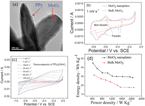 | ||
| Fig. 4 (a) TEM micrograph of PPy coated MoO3 nanorods, (b) CV curves of the bulk and nanoplates MoO3, (c) CV curves of the PPy@MoO3 nanocomposite at different scan rate and (d) Ragonne plot of the ASCs based on MoO3//AC in 0.5 mol l−1 Li2SO4 solution (modified from ref. 6c and 49c). | ||
In terms of the electrochemical performance, it seems that the MoO3 nanoplates exhibit the best performance among the nanoparticles, nanorods and nanoplates though they are tested in different solutions. The deposited MoO3 nanoparticles present 477 F g−1 at 0.1 mA cm2 in a solution of 0.005 mol l−1 H2SO4 and 0.095 mol l−1 Na2SO4 in the potential range of −0.3 − −0.55 V (vs. Ag/AgCl).46 Nanorods synthesized at 180 °C exhibit a specific capacitance of 30 F g−1 at a scan rate of 5 mV s−1, and remains 24 F g−1 at 100 mV s−1 in 1 mol l−1 H2SO4 solution in the potential range of −1.0–1.0 V (vs. Ag/AgCl). Its redox peaks are not symmetric. The anodic ones are mainly situated above 0.0 V (vs. Ag/AgCl), and the cathodic ones below 0.0 V (vs. Ag/AgCl).47 MoO3 nanoplates present higher capacitance than that of the bulk one in 0.5 mol l−1 Li2SO4 solution. The latter presents only one clear couple of redox peaks at −0.72/−0.6 V (vs. SCE) in its CV curve (Fig. 4b). As to the former, there are two couples of redox peaks at −0.39/−032 V and −0.75/−0.59 V (vs. SCE) (Fig. 4b), respectively. These peaks correspond to the reversible intercalation/de-intercalation of lithium ions into/out of the MoO3 phase, and contribute to pseudocapacitance.
The nanocomposite of MoO3 and carbon exhibits a higher capacitance than those of the pure milled graphite and MoO3 in 3 mol l−1 KCl aqueous solution in the range of −0.5–0.5 V (vs. Ag/AgCl). This improvement is attributed to its unique structure, in which MoO3 nanoparticles (with a size range of 1−180 nm) are uniformly dispersed in an electrically conductive carbon host.49b The ZnO@MoO3 core/shell nanocomposites delivers a specific capacitance of 236 F g−1 at the scan rate of 5 mV s−1, which is much larger than that of MoO3 nanoparticles.48 The nanocomposite of PPy@MoO3 shows very good rate capability as shown in Fig. 4c, which is due to the conductive PPy coating. In addition, the coating can ensure a good cycling performance to prevent the dissolution of Mo ions.49c
When assembled into an ASC using AC as the positive electrode, as shown in Fig. 4d, the ASC can deliver a high energy density of 45 Wh kg−1 at 450 W kg−1, and maintain 29 Wh kg−1 even at 2 kW kg−1. In contrast, the energy density for the bulk MoO3 is 32 Wh kg−1 at 450 W kg−1 and fades to 17.5 h kg−1 at 2 kW kg−1. Evidently, this good rate behavior is due to the MoO3 nanoplates. The average charge and discharge voltages for this ASC are about 1.10 and 0.95 V, respectively.6c
2.5 Other negative electrode materials
Other negative electrode materials include Ru(OH)2, n-doped polymers such as PAn and PPy,5a,16b,16c,50a VN,50b and so on.Ru(OH)2 can take place the following similar reactions as eqn (9):
| Ru(OH)2 ↔ RuOδ(OH)2−δ + δH+ + δe− | (9) |
It is sometimes called hydrous ruthenium oxide, mainly related to RuO2, which is used as a positive electrode for ASCs, and this part will be expounded in the following 3.2.1 section.
As for conductive polymers such as PAn and PPy, their reaction mechanism is due to the n-doping of cations:
| CP + e− + C+ ↔ CP−C+ | (10) |
They have been studied widely, and some reviews can be referred.5a,16c,16d Since there is not much progress in this field, they will not be expounded here.
In the case of VN, it can produce pseudo-capacitance in acid, alkaline and neutral solutions. The main reason is the existence of surface nitride oxides (VNxOy), which can take place the following reactions:
| 2 VNxOy + SO42− + H2O ↔ VNxOy/SO42− + VNxOy−OH + H+ + e− (acid) | (11) |
| VNxOy + OH− ↔ VNxOy/OH + e− (alkaline) | (12) |
| VNxOy + NO3− ↔ VNxOy/NO3 + e− (neutral) | (13) |
The electrical double layer capacitance and pseudo-capacitance in 2 mol l−1 KOH and 0.5 mol l−1 H2SO4 electrolytes is greater than 1 mol l−1 NaNO3 electrolyte. The main reason is due to the small sizes of OH−. Their respective capacitance is 114, 273 and 45.7 F g−1.50b
3. Positive electrode materials for asymmetric supercapacitors
In the present section we focus on the most recent work regarding the latest development on positive electrode materials for ASCs. Actually, as discussed above, carbonaceous materials like AC, CNT and graphene and oxides such as MoO3 and V2O5 can also be used as negative electrode materials for ASCs. Particular attention in this section is paid to oxides such as RuO2, MnO2, MoO3, V2O5, PbO2 and cobalt oxides, Ni(OH)2, intercalation compounds and other materials.3.1 Carbonaceous materials
Carbonaceous materials mentioned in Section 2.1 including AC, porous carbons such as NPCs, CNTs and graphene can also be used as positive electrode materials for ASCs, and their action mechanism is as eqn (14):| Carbon + A− ↔ Carbon/A + e− | (14) |
Where A− and/refer to anion and interface, respectively.
Of course, acid, alkaline and neutral aqueous solutions can be used as electrolytes.51 The parameters such as porosity, pore size and its distribution and functional groups are also crucial to affect their electrochemical performance, which will not be expounded further. The former discussion in 2.1 section about their preparation can also be referred. Here just several examples are provided.
An AC can be prepared from the carbonization of resorcinol-formaldehyde resin with KOH as activation agent to present a high BET surface area of 1673 m2 g−1 with a great number of micropores of a diameter less than 1.5 nm.51b Carbon materials can also form composites such as AC with CNTs.51c
MWCNT thin films with controlled thickness can be prepared by layer-by-layer (LBL) assembly of surface functionalized MWCNTs (Fig. 5).52a For example, negatively and positively charged MWCNTs are functionalized on their exterior walls with carboxylic acid groups52b and amine groups,52c respectively. By LBL assembly using their stable dispersions, MWCNT films consisting of well-dispersed MWCNTs can be achieved as shown in Fig. 5.
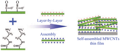 | ||
| Fig. 5 Layer-by-layer assembled MWCNT thin film with positively and negatively charged MWCNTs (modified from ref. 52a). | ||
Graphene can be prepared by electrochemical reduction of graphene oxide instead of chemical reduction. The oxygen content is significantly decreased and the sp2 carbon is restored.52d
In terms of the electrochemical performance of the carbon materials, the above AC with micropores of 1.5 nm shows good rate performance at the scan rates from 2 to 40 mV s−1, which is shown in Fig. 6a. It presents higher specific capacitance, higher power density and higher energy density in comparison with the commercial activated carbon (Maxsorb: Kansai, Japan) as positive electrode for ASCs. Its specific capacitance is 500 F g−1 in 6 mol l−1 KOH electrolyte at a current density of 233 mA g−1, which remains 302 F g−1 even at a high current density of 4.6 A g−1. This is ascribed to well-developed micropores smaller than 1.5 nm, the presence of electrochemically oxygen functional groups and low equivalent series resistance.51b
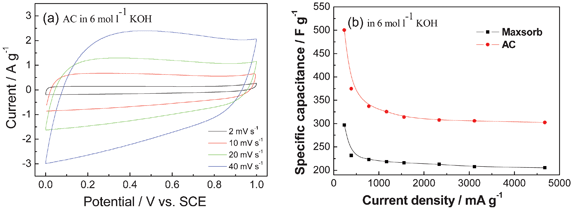 | ||
| Fig. 6 (a) CV curves of an AC in 6 mol l−1 KOH aqueous electrolyte and (b) comparison of gravimetric capacitances against current density for the AC and the commercial Maxsorb carbon (modified from ref. 51b). | ||
For the LBL MWCNT thin films, they present an average capacitance of 159 F g−1 in 1.0 mol l−1 H2SO4 solution, which is considerably higher than those of vertically aligned CNTs and conventional CNT electrodes53 due to the high CNT densities and well developed nanopores.52a
The composite of AC with CNTs shows a capacitance of 295 F g−1 at 0.125 A g−1 and decreases to 180 F g−1 at 100 A g−1 in the voltage range of −1–1 V in 2 mol l−1 H2SO4. CNT addition provides inter-particle spacing and bridging media leading to a reduction in the Warburg diffusion and electrical resistance. The composite shows superior stability, with no decay of specific capacitance after 10000 cycles.51c
Graphene from the electrochemical reduction of GO exhibits a much higher electrochemical capacitance and cycling durability than CNTs and chemically reduced graphene. Their specific capacitances can be measured with cyclic voltammetry (20 mV s−1) in the potential range of 0–0.9 V (vs. NHE) is 165, 86, and 100 F g−1, respectively, in 0.1 mol l−1 Na2SO4 solution.52d
3.2 Oxides
RuO2 usually exhibits two phases: a crystal phase (RuO2, rutile phase) and an amorphous hydrous phase (RuO2·xH2O). The annealing temperature is a key factor affecting the morphology, which exists usually in the form of the nanostructure such as nanoparticles, nanorods and nanofibers. High annealing temperature, for example from 300 to 800 °C, leads to the crystalline phase of RuO2 and less water content, resulting in the change of the number of active reaction sites, as well as the electron and proton conductivity. Electronic conductivity of RuO2 nanocrystals is balanced with the protonic conductivity of the ambient structural water when one mole of RuO2 is hydrated by 0.58 mole of water (RuO2·0.58H2O). Primary particulates will aggregate into secondary particles to form 3D framework porosity at above 200 °C. High specific surface area with nanoporous structure is also important to achieve high capacitance.5a
For positive electrode of ASCs, nanostructured RuO2 is more attractive. It can be synthesized via various methods including potentiodynamic deposition, electrostatic spray deposition, chemical precipitation colloids, oxidative synthesis, hydrothermal synthesis, incipient wetness method, a combination of chemical vapor deposition (CVD), and electrolytic production.5a For example, 3D mesoporous architecture of RuO2·xH2O nanotubular arrayed electrodes can be synthesized by anodic deposition technique,54a and thin-film RuO2 electrodes are prepared by cathodic electrodeposition on a titanium substrate.54b
RuO2 is the most promising electrode material, but the lack of abundance and the expensive cost of the precious metallic element (Ru) are drawbacks for commercialization of supercapacitors employing this element. As a result, and as an alternative material for pure RuO2, many composites containing RuO2 are synthesized by various methods.5a For example, the composites of amorphous Ru1−yCryO2/TiO2 nanotubes are synthesized by loading various amount of Ru1−yCryO2 on TiO2 nanotubes through a redox reaction of aqueous K2Cr2O7 with RuCl3. The 3D nanotube framework of TiO2 offers a solid support for Ru1−yCryO2 active materials, allowing the active material to be readily available for electrochemical reactions, and an increase in the efficient use of active materials. Different morphologies of RuO2 can be prepared to get more efficient use of RuO2. For example, core-shell structured RuO2@VO2 and RuO2@TiO2 nanotube can be prepared.54c,54d and anchored onto the surface of the GSs by strong chemical interactions between the residual oxygen-containing functional groups on the GSs and ruthenium hydroxide NPs, or by van der Waals interactions between the GSs and the NPs. Finally, to convert ruthenium hydroxide NPs into hydrous and amorphous RuO2 NPs, annealing is carried out at 150 °C.59a
Of course, it can also form composites with carbon materials such as AC, CNT, NPC and graphene. For example, the RuO2@AC composite can be synthesized by a sol–gel method on the surface of AC.55 Ruthenium oxide@ordered mesoporous carbon composites materials can be prepared by impregnating an ordered mesoporous carbon, CMK-3, with RuCl3·xH2O solution followed by annealing in nitrogen atmosphere.56 CNTs acts as a support due to its good electronic conductivity and accessible surface textures, and RuO2 can be dispersed on CNTs with different arrays.52,57,58 Composites with graphene are prepared by combining a sol–gel process and low-temperature annealing. For example, as shown in Fig. 7a, at first, the solvent-free graphene sheets (GSs) are re-dispersed in a mixed solvent of ethanol and water, which leads to the release of the stacked sheets to give well-separated individual sheets. Then RuO2 particles are anchored onto well-separated individual GSs during the sol–gel process, and the presence of water offers an aqueous medium (NaOH) for the formation of ruthenium hydroxide. Then ruthenium hydroxide nanoparticles (NPs) are formed by the reaction of RuCl3 and NaOH.
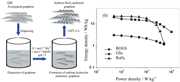 | ||
| Fig. 7 (a) The preparation scheme of RuO2/GSs composites (ROGS) and (b) Ragone plot for the as-prepared GSs, RuO2, and ROGS (Ru, 38.3 wt%) (modified from ref. 59a). | ||
The charge storage/delivery mechanism of RuO2·xH2O can be presented in eqn (15) and (16).
| RuOx(OH)y + δH+ + δe− ↔ RuOx−δ(OH)y+δ | (15) |
| RuO2 + H+ + e− ↔ RuOOH | (16) |
RuO2 can present a very good rectangular shape in the CV curves. For example, the 3D mesoporous RuO2·xH2O nanotubular arrayed electrode can retain this shape up to 1000 mV s−1 (Fig. 8a). Its capacitance does not fade much with the scan rate (Fig. 8b). It shows a specific power of 4320 kW kg−1 and specific energy of 7.5 Wh kg−1 in 1.0 mol l−1 H2SO4 solution at the potential range of 0–1.0 V (vs. Ag/AgCl), respectively.54a The specific capacitance and charge–discharge performance of the thin-film RuO2 are dependent on the electrode thickness. The thinner the electrode thickness is, the higher the specific capacitance will be. For example, a maximum specific capacitance of 788 F g−1 is achieved with an electrode thickness of 0.0014 g cm−2 in 0.5 mol l−1 H2SO4 solution at the potential range of 0–0.6 V (vs. Ag/AgCl).54b The ASC with anthraquinone-modified carbon fabric as the negative electrode and RuO2 as the positive electrode shows a maximum energy density of 26.7 Wh kg−1 in 1 mol l−1 H2SO4 solution in the voltage range of 0–1.3 V. It can arrive at an energy density of 12.7 Wh kg−1 at 0.8 A cm−2 discharge rate with average power density of 17.3 kW kg−1.59b
 | ||
| Fig. 8 (a) CV curves at different scan rates and (b) dependence of the capacitance on the scan rate for an annealed RuO2·xH2O nanotube arrayed electrode (0.19 mg cm−2) in 1.0 mol l−1 H2SO4 solution (modified from ref. 54a). | ||
A common method for increasing the electrochemical charge stored per RuO2 is the addition of a second metal oxide, such as VO2. In an acidic solution, specific capacitance exceeding 1200 F g−1 based on RuO2 in 0.5 mol l−1 H2SO4 solution is obtained for Ru0.35V0.65O2 in the potential range of 0.1–1.3 V (vs. NHE).54c The ASC consisting of AC as the negative electrode and a RuO2@TiO2 nanotube composite as the positive one has good electrochemical performance in 1 mol l−1 KOH solution in the voltage range of 0–1.4 V. The energy density reaches 12.5 Wh kg−1 at a power density of 150 W kg−1. When the power density increases up to 1207 W kg−1, its energy density decreases to 5.7 Wh kg−1. The ASC also exhibits a good cycling performance and keeps 90% of initial capacity over 1000 cycles.6d The RuO2·xH2O@TiO2 nanocomposite exhibits weakly mass-dependent specific capacitance and high-power capacitive characteristics in comparison with pure RuO2·xH2O.54d
The nanocomposite of RuO2 with carbon materials can achieve both high power and high energy density with low cost no matter whether it is in acid or alkaline solutions.55,56,58,59 For example, RuO2 electrodeposited on a highly porous SWCNT film can show a maximum specific capacitance of 1715 F g−1 based on the weight of RuO2,58d which is closely approaching the theoretical maximum capacitance (2000 F g−1). Ruthenium oxide@ordered mesoporous carbon (CMK-3) has a higher specific capacitance due to the high specific surface area of the mesoporous carbon and the pseudo-capacitance of amorphous RuO2.56 However, the electrochemical performance of most porous carbon-based electrodes is limited by the surface area blocked by the loaded RuO2 particles that may not be accessible by the aqueous electrolyte used; therefore the advantages of high-surface-area carbon-based double-layer capacitance cannot be fully utilized in these composites. As a result, RuO2@graphene sheets (GSs) composites perform much better than other RuO2@carbon composites in terms of the absence of pore blockage during the RuO2-loading process and the anchoring of fine RuO2 particles uniformly on the surface of conducting GSs (Fig. 7b).59a The RuO2@GS composite exhibits high specific capacitance (570 F g−1 for 38.3 wt% Ru loading), enhanced rate capability, excellent electrochemical stability (97.9% retention after 1000 cycles), and high energy density (20.1 Wh kg−1) at low charge/discharge current rate (100 mA g−1).59a
| MnO2 + δM+ + δe− ↔ MnO2/Mδ | (17) |
Up to now, several crystallographic phases of MnO2, i.e., ramsdellite-, α-, β-, γ-, δ-, and λ- phases have been reported according to the different linking manner of [MnO6] octahedral, and their different crystalline phases are described by the size of the tunnel formed with the number of octahedra subunits (n × m), and the tunnel type as well as size is presented in Table 3.5a
| Crystallographic form | Tunnel type | Tunnel size (Å) |
|---|---|---|
| ramsdellite | (1 × 2) | 2.3 |
| α | (1 × 1), (2 × 2) | 1.89, 4.6 |
| β | (1 × 1) | 1.89 |
| γ | (1 × 1), (1 × 2) | 1.89, 2.3 |
| δ | Interlayer distance | 7.0 |
Nanostructuring and forming composites with a high surface area and conductive matrix are the two major strategies to improve the poor electronic conductivity of MnO2 in the development of high-performance MnO2-based electrodes for supercapacitors applications.60a
The crystallographic structure and morphology of nanostructured MnO2 are greatly dependent on synthetic factors such as the pH value, concentration of inorganic cation templates and potential. 5a,61 Porous MnO2 (pore size ca. 5–30 nm) can be prepared by an organic–aqueous interfacial method. The surface area and pore size distribution of MnO2 can be controlled by adjusting the reaction time and the content of surfactant in the aqueous phase. High surface area mesoporous MnO2 with an α-phase crystalline structure has been synthesized by the reduction of potassium permanganate with ethylene glycol under acidic conditions.5a Hydrothermal or solvothermal synthesis is another important method to prepare nanostructured MnO2.61 A simple hydrothermal process based on KMnO4, sulfuric acid and Cu scraps can prepare α-MnO2 hollow spheres and hollow urchins. The hollow sphere or urchin structured α-MnO2 materials possess a highly loose, mesoporous cluster structure consisting of thin plates or nanowires.62a
In the case of the composites of MnO2 with other materials, most of the latest reports are related to carbonaceous materials such as carbon aerogels,63 AC,7b,64 CNTs and graphene. Formerly there are a few reports on their composites with conductive polymers,16c which will not be expounded upon here. Mesoporous MnO2 can be deposited on AC to achieve a composite.7b,64 Zn2SnO4@MnO2 core/shell nanocable-carbon microfiber composites are fabricated as follows: the crystalline Zn2SnO4 nanowires grown radially on carbon micro fibers (CMFs) are uniquely serve as highly electrical conductive cores to support redox active MnO2 shells with a highly electrolytic accessible surface area and provide reliable electrical connections to the MnO2 shells, enabling full utilization of MnO2 and fast electronic and ionic conduction through the electrode.65 As formerly mentioned, CNTs present higher electronic conductivity than AC, and there are quite some composites of CNTs with MnO2.7d,8,57,66–68
For example, the composites of MnO2 nanowires with MWCNTs can be easily prepared by a hydrothermal method.7d A binder-free MnO2@CNT array electrode with hierarchical porous structure, high surface area and superior conductivity is fabricated by combining electrodeposition and a vertically aligned CNT array framework.66
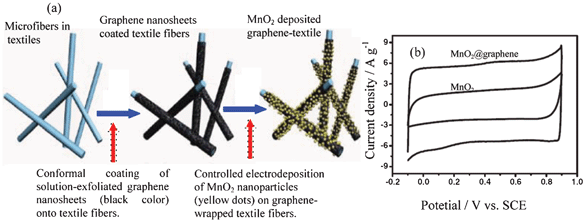
Amorphous or poorly crystalline MnO2 nanoparticles can be deposited onto ultraporous activated graphene from KMnO4 solution.29 A solution-phase assembly can be used to prepare a composite of MnO2 nanowires@graphene sheets.8c Graphene can be decorated with flower-like MnO2 nanostructures by electrodeposition to achieve a composite.69 The graphene@MnO2-textile composite can be prepared by the process shown in Fig. 9a. Firstly, the highly porous textile fibers are coated by graphene nanosheets (GNSs) that are prepared via a facile solution-based exfoliation process. The coating is done by a simple “dip and dry” process, which is similar to that widely used in the textile industry for dyeing fabrics and fibers. The second is the controlled deposition of MnO2 nanomaterials on the as-prepared conductive textile fibers. Uniform deposition of MnO2 nanomaterials is achieved on the surfaces of individual microfibers over almost the entire network of the porous textiles. Moreover, electrodeposited MnO2 particles show a nanoflower-shaped hierarchical architecture and a clear interface between the MnO2 nanoflower and the underneath GNSs.8a Conductive polymers can be further coated on MnO2@MWCNTcomposites.66,67 Other kinds of conductive matrix can also be a support for MnO2 such as Zn2SnO4,70 TiN71 and nanoporous gold.72,73
 | ||
| Fig. 9 (a) Schematic illustration of two key steps for preparing hybrid MnO2-nanostructured textiles@graphene and (b) CV curves of an optimized MnO2@graphene at different potential windows at the scan rate of 20 mV s−1 in 1 mol l−1 Na2SO4 solution (modified from ref. 8a and 8b, respectively). | ||
MnO2 can be used in acid,29 alkaline and neutral solutions such as KCl,60 Li2SO4,61 Na2SO48c,69 and K2SO4,61 and redox peaks in mostly rectangular CV curves can be observed (Fig. 10a). The redox peaks are related to the intercalation and de-intercalation of cations, which has been completely proved by X-ray photonic spectroscopy (XPS). At the current density of 0.2 A g−1, the binding peak of O1s from XPS analysis shifts significantly to a higher energy of 531.0 eV after the first discharge in Li2SO4 solution, which is ascribed to the intercalation of Li+ ions into the MnO2 lattice since Li–O coordination has a higher O1s binding energy of 531.3 eV. The binding energy peaks of Mn2p in the MnO2 electrode shift slightly toward lower position after discharge, which is due to the valence transformation of Mn4+ to Mn3+.7c
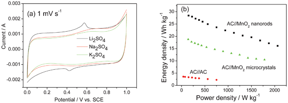 | ||
| Fig. 10 (a) CV curve of MnO2 in 0.5 mol l−1 different neutral electrolytes and (b) Ragone plots of the hybrid supercapcitors AC//MnO2 nanorods, AC//MnO2 microcrystals supercapacitor and AC//AC supercapacitor in 0.5 mol l−1 K2SO4 electrolyte (modified from ref. 7c). | ||
The pH affects the stable working potential of MnO2 and the widest stable electrochemical window is achieved at pH ≈ 6.4 in the range of 6.4–10.60c The morphology and surface area of the prepared MnO2 present great influence on the specific capacitance. 61,74–76 For example, the specific capacitance obtained from the electrochemically oxidized manganese films having hydrated and porous structure is generally higher than those from thermally oxidized samples.74,75 The MnO2 nanorods show much higher energy density than that of the micrometer one.7c MnO2 nanoflowers can also be coated on Ni(OH)2 nanoflakes.62b
Similar to carbonaceous materials as negative electrodes,9a different ions will show different capacitance. Just as shown in Fig. 10a, the MnO2 nanorods have the largest capacitance (201 F g−1) in Li2SO4 solution at the slow scan rates since the reversible intercalation/de-intercalation of Li+ in the solid phase produces an additional capacitance besides the capacitance based on the absorption/desorption reaction. At the fastest scan rates they show the largest capacitance in the K2SO4 solution due to the smallest hydration radius of K+ and the highest ionic conductivity of the solution.7c
Formerly, it was reported that the oxygen in the solution would affect the cycling life of MnO2.7a However, if MnO2 exists in the nanorods with a low crystallinity, the oxygen does not influence the cycling life. For example, after 23000 full cycles, there is no clear evidence of capacitance fading.7c
After forming composites with conductive materials, the movement of electrons is greatly improved, leading to an enhancement of the capacitance and rate capability. For example, the binder-free MnO2@CNT array composite shows excellent rate capability (50.8% capacity retention at 77 A g−1) and high capacitance (199 F g−1 and 305 F cm−3).66 The PAn@MnO2-MWCNTs composite delivers remarkably enhanced specific capacitance and cycling stability compared to MnO2-MWCNTs, where the highest specific capacitance (350 F g−1) is obtained at a current density of 0.2 A g−1, higher than 92 F g−1 for pristine MWCNTs and 306 F g−1 for MnO2-MWCNTs.67 Hierarchical MnO2 nanospheres@CNTs@conducting polymer ternary composite achieves a specific capacitance of 427 F g−1 in 1 mol l−1 Na2SO4 solution.70
The incorporation of graphene into the composites can provide them with the unique properties of graphene and also possibly induce new properties and functions based on synergetic effects. Fig. 9b shows the comparison of the CV curves for the MnO2@graphene composite and the virginal MnO2 in 1 mol l−1 Na2SO4 aqueous solution at 20 mV s−1. The specific capacitance of the composite is evidently much higher than that of the virginal MnO2.8b In neutral solution such as 1 mol l−1 KCl, the specific capacitance for the composite of nanoflower MnO2 with graphene is 328 F g−1 at the potential range of 0–0.9 V (vs. Ag/AgCl), much higher than those of the graphene and MnO2.69 In 1 mol l−1 H2SO4 solution, the composite of MnO2 nanoparticles with ultraporous activated graphene exhibits a specific capacitance of 175 F g−1 on the basis of the total mass of active materials of the positive and negative electrodes at a current density of 0.25 A g−1.29
In the case of the MnO2 nanowires@graphene composite, the nanostructured MnO2 can prevent the aggregation of graphene sheets caused by van der Waals interactions, consequently leading to an increase in the available electrochemical active surface area and a suitable porous structure for energy storage.8c The graphene@MnO2 composite is a flexible film and achieves a high specific capacitance (372 F g−1) with excellent rate capability without the need of current collectors and binders.77a The unique characteristics of the MnO2@graphene nanostructured textiles make them promising candidates for high-performance ASC electrode materials: 1) 3D porous micro structure of the polyester textiles allows conformal coating of GNSs and subsequent loading of MnO2 and facilitates easy access of electrolyte ions to electrode surfaces; 2) the graphene nanosheet coating serves as high-surface-area, conductive paths for the deposition of MnO2, providing excellent interfacial contact between MnO2 and graphene for fast electron transport; 3) nanoflower architecture of the electrodeposited MnO2 offers large electrochemically active surface areas for charge transfer and reduced ion diffusion length during the charge/discharge process.8a
In the case of composites of MnO2 with other conductive materials, their electrochemical performance is also greatly improved. In the case of the MnO2@Zn2SnO4 composites, the mass loading of MnO2 can be up to 60% and it still shows a capacitance as high as 200 F g−1 including excellent charge/discharge rate and cycling stability.65 The coaxial array of MnO2@TiN nanotube composite shows a capacitance of 681 F g−1 at a current density of 2 A g−1 and excellent rate capability (267.2 F g−1 at a impressing scan rate of 2000 mV s−1) in1 mol l−1 Na2SO4 solution due to the electronic conducting TiN framework.71 The MnO2@nanoporous gold composite can show a surprising high specific capacitance (about 1145 F g−1) that is close to the theoretical value.73
In the case of the ASCs, different negative electrodes can be used. The active material weight ratios (positive to negative),77b voltage window77c and different aqueous electrolytes61 will affect the performance of the assembled ASCs. As shown in Fig. 10b, the ASC of AC//MnO2 nanorods can have higher energy density and better rate capability than that of AC//MnO2 micrometer.7c When MWCNTs are introduced into MnO2 nanowires, their rate capability is very good. The energy density of the ASC of AC//MnO2 nanowires@MWCNTs stays almost constant with an increase of power density even at 3340 W kg−1.7d Moreover, the capacity of this ASC does not change much after 13 000 cycles even when oxygen is not removed.7d In 1 mol l−1 H2SO4 solution, the ASC of graphene//MnO2 nanoparticles@graphene can operate up to 2 V. Its energy density can be 24.3 Wh kg−1 (at a power density of 24.5 kW kg−1) and power density be 32.3 kW kg−1 (at an energy density of 20.8 Wh kg−1).29 A capacitance retention of 80.5% over 5000 cycles is achieved for this device.29 In 1 mol l−1 Na2SO4 solution, the ASC based on graphene//MnO2 nanowires@graphene can be reversibly cycled in the high-voltage range of 0–2.0 V and exhibits an energy density of 30.4 Wh kg−1, which is much higher than those of symmetric supercapacitors based on graphene//graphene (2.8 Wh kg−1). Moreover, it has a high energy density of 7.0 Wh kg−1 even at a power density of 5000 W kg−1 and presents an acceptable cycling performance.8c However, the ASC of graphene//MnO2 nanowires@graphene presents a little worse cycling performance (79% retention after 1000 cycles) compared to AC//MnO2 nanowires@MWCNTs and graphene//MnO2 nanoparticles@graphene. When AC nanofibers are used as the negative electrode and the composite graphene@MnO2 as the positive one, an energy density of 51.1 Wh kg−1 can be obtained for this ASC.8b
These results are encouraging and represent significant progress toward high-energy and safer ASC devices at low cost.
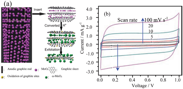 | ||
| Fig. 11 (a) Illustration of the formation of the composite of α-MoO3-decorated graphene sheets by electrolytic exfoliation from graphite with the assistance of molybdate and (b) CV curves of the composite in 6 mol l−1 KOH (modified from ref. 49a). | ||
In neutral or alkaline solutions, the redox peaks are not clear (Fig. 11b).49a,49b In acid solutions such as 1 mol l−1 H2SO4, the redox peaks can be clearly identified.49b After the heat treatment at 200 °C, the composite of MoO3@graphene sheets can exhibit a high specific capacitance, up to 86.3 F g−1, in the voltage range of 0–1 V in 6 mol l−1 KOH solution due to very high electronic conductivity (up to 5367 S m−1).49b
Electrospinning, regarded as a simple, one-step, cost effective method, is preferred over the other processes in synthesizing nanofibers with diameters ranging from tens nanometres to several micrometres.79a Furthermore, the structure, surface morphology and diameter of the fibers can be easily controlled by adjusting the variables of the electrospinning method, such as the applied potential, precursor concentration and flow rate of the solution. It is used to prepare V2O5 nanofibers (VNF).79b Hydrothermal and templates methods can be used to prepare nanobelts, nanorolls and nanoporous V2O5.6a,78a,79c
Conductive materials are also introduced to modify V2O5. For example, using arc-ion plating under Ar gas flow, a composite of V2O5@CNTs is achieved.80a A composite based on V2O5@SnO2@CNT is prepared by a hydrothermal method in an autoclave.80b Highly ordered mixed V2O5@TiO2 nanotubes can be formed by self-organizing anodization of Ti–V alloys.80c
Amorphous vanadium oxide prepared by quenching V2O5 fine powder heated at 950 °C for 30 min into a bath of deionized water has a specific capacitance of 350 F g−1 in KCl and the pH of electrolyte affects the potential window and capacity obviously.5a V2O5 usually has a higher capacitance in KCl solutions than that in NaCl or LiCl ones. In neutral 2 mol l−1 KCl electrolytes, maximum capacitance of 214 F g−1 for the porous V2O5 is obtained from CV at the scan rate of 5 mV s−1 in the voltage range of −0.2–0.7 V (vs. SCE).78a,78b For the electrospun V2O5 nanofibers, they yield a maximum capacitance of 190 F g−1 in neutral KCl solution.79b The V2O5·0.6H2O nanobelts show four distinct couples of redox peaks in the potential range of 0–1.0 V (vs. SCE) in 0.5 mol l−1 K2SO4 (Fig. 12a). The redox peaks of V2O5·0.6H2O electrode in K2SO4 can be ascribed to the intercalation/de-intercalation of K+ ions into/fromV2O5·0.6H2O lattice accompanied with the electrochemical conversion of V5+ to different valence states. Its specific capacitance can be up to 180.7 F g−1 at 2C.6a
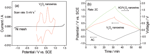 | ||
| Fig. 12 (a) CV curve of V2O5 nanowires and Ni mesh (current collector) and (b) charge/discharge curves of AC//V2O5 nanowires in 0.5 mol l−1 K2SO4 aqueous solution (modified from ref. 6a). | ||
In the case of the composites, for example, the specific capacitance of the composite of V2O5@mesoporous carbon is increased by 61% in 1 mol l−1 KNO3 solution comparing with that of the virginal mesoporous carbon.80a The electrochemical performance of V2O5@CNTs is significantly improved as compared with those of the bare oxide films and virginal CNTs. The CNTs covered with uniformly dispersed oxides lead to a significantly improved capacitive performance, as compared with the bare oxide films.80b The SnO2–V2O5–CNT nanocomposite presents a capacitance of 121.4 F g−1 at 100 mV s−1 in 0.1 mol l−1 KCl solutions.80c The higher specific capacitance of V2O5@SnO2@CNT demonstrates that the electronic properties can be changed favorably with a suitable choice of the additive in the electrode material.80c
The specific capacitance of the V2O5@TiO2 nanotubes can reach to 220 F g−1 which is stable during cycling. The supercapacitive behavior can be ascribed to the V4+/V5+ redox switching of the V2O5 phase embedded in the TiO2 matrix. The good cycling stability of the mixed V2O5–TiO2 nanotube arrays is due to the highly ordered 3D TiO2-stabilized V2O5 nanotube structure which restrains the strain during ion intercalation.80d
The ASC consisting of AC//V2O5·0.6H2O presents a stable voltage between 0 and 1.8 V (Fig. 12b). It delivers an energy density of 29.0 Wh kg−1 based on the total mass of the active electrode materials, a very good rate behavior with energy density of 20.3 Wh kg−1 at power density of 2000 W kg−1, and also a rather good cycling performance.6a The species of aqueous electrolyte, current density, potential range and the active mass ratio of AC to V2O5 have great effect on the capacitive performance of the ASC. When the mass ratio of AC to V2O5 is to 3:1, the capacitance of the AC//V2O5 ASC is similar to that of the V2O5//V2O5 symmetric supercapacitors.79d
However, the cycling performance of V2O5 is still needed to improve due to the dissolution of V into the aqueous electrolytes leading to capacity fading, which is an urgent problem to be solved.
As a surface reaction, the redox activity of the PbO2 relates to the morphology and structure (α-PbO2 or β-PbO2) and its electrochemically active surface area should be increased as the positive electrode of an ASC. It has been recognized that porous structured PbO2 should present more electrochemical activities. As a result, thin film, porous and nanostructured PbO2 have been prepared and different substrates have been investigated.81b,82 For example, highly ordered macroporous films of both α-PbO2 and β-PbO2 are prepared by electrodeposition through templates assembled from submicron diameter PS spheres assembled on either gold or indium tin oxide substrates.82b Super-large dendrites (about 500 μm) composed of trigonal PbO2 nanoplates are synthesized by electrodeposition.82c These prepared super-large PbO2 dendrites composed of orderly arranged trigonal nanoplates.
The CV curve of PbO2 exhibits one couple of well-defined redox peaks. The potential difference between the oxidation and reduction peaks is usually very large due to the poor kinetics of the PbO2/Pb2+ couple. The thin film PbO2 on Ti/SnO2 foil can deliver a discharge specific capacitance of 79.9 F g−1 at a current of 0.75 mA cm−2 and 74.1 F g−1 at 10 mA cm−2, based on the total weight of both active electrode materials, and the capacitance retains 83% of its initial value after 3000 deep cycles at the 4 C rate.82a The electrochemical activity of the resulting macroporous β-PbO2 is greater than that of the corresponding plain film.82b The super-large PbO2 dendrites composed of orderly arranged trigonal nanoplates can promote the remarkable enhancement in the electrochemical performances of the prepared ASCs.82c As shown in Fig. 13, the current response and capacitance of the super-large PbO2 dendrites are much larger than that of the small dendrites in 5.0 mol l−1 H2SO4 solution.
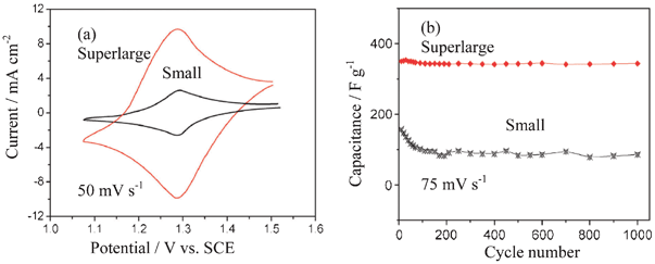 | ||
| Fig. 13 (a) Typical CV curves and (b) cycling performance of super-large PbO2 dendrites composed of trigonal nanoplates and the small dendrites in 5.0 mol l−1 H2SO4 solution recorded a scan rate of 75 mV s−1 (modified from ref. 82c). | ||
In the case of the ASCs using PbO2 as the positive electrode, their performance is dependent on the positive electrode, negative electrode and their ratio. In the voltage range of 0.8–1.8 V, this AC//PbO2 delivers a specific energy density of 29.0 Wh kg−1 at a power density of 1010 W kg−1 based on the total weight of both active electrode materials when the value of mass ratio of AC to PbO2 is three. After 4500 deep cycles at the charge-discharge current of 200 mA g−1, the specific capacitance remains at 64.4 F g−1 with the specific energy density of 32.2 Wh kg−1 and it only decays 10% of its initial capacity.8d
In the ASC based on AC//PbO2 nanowires, CH3SO3H is added to prevent PbO2 from sulfation. Its energy density can be 29 Wh kg−1 at a current density of 10 mA cm−2. There is no sign of degradation during more than 5000 cycles.9a For comparison, the AC//PbO2 thin film system exhibits a 50% decrease of its performances at the similar conditions.
| Co3O4 + H2O + OH− ↔ 3CoOOH + e− | (18) |
| 3Co(OH)2 + 2OH− ↔ Co3O4 + 4H2O + 2e− | (19) |
Various methods including solid state syntheses, wet chemical processes, electrodeposition, radio frequency magnetron sputtering and microwave methods can be used to prepare tailored Co3O4. To achieve good electrochemical performance, the specific surface area is an important factor. Thin film83a,83b and nanostructured Co3O4 are preferred.83c Co3O4 thin films can be deposited directly on current collectors via a single step solution precursor plasma spray route. In this approach, an aqueous solution containing cobalt acetate is axially fed into plasma plume to produce nanoparticulates of Co3O4via an accelerated thermo-chemical conversion process, which are eventually deposited on a current collector substrate. Thus, Co3O4 shows the nano particulate structure with porosity.83b Nanostructured Co3O4 materials are usually prepared from powders using sol-gel and hydrothermal methods. Utilizing sawdust as a bio-template, Co3O4 nanoparticles with the average diameter of about 40 and 60 nm are prepared.83c
Co3O4 can form composites with conductive materials such as CNTs and graphene. Composites of cobalt oxides/CNTs are prepared by adding and thermally decomposing cobalt nitrates directly onto the surface of CNTs to form cobalt oxides.84a A microwave-assisted method can be used to prepare Co3O4@graphene nanosheet (GNS) composite with homogeneous distribution of Co3O4 nanoparticles (3–5 nm in size) on graphene sheets.84b Using a mild hydrothermal method, Co3O4 nanoplates with a length of 0.5–1 μm and width of 100–300 nm can be homogeneously distributed on the surface of GNSs.84c
As to Co(OH)2, it mainly consists of α- and β-phases. Simple cathodic deposition can achieve films from their chloride precursor in aqueous media.85a A highly uniform, porous nanostructured β-Co(OH)2 is synthesized via a hydrothermal and template-free approach. The nanostructures consist of amassing, arbitrarily layered, interconnecting nanosheets, resulting in a flower-like structure with many fissures.85b Mesoporous α-Co(OH)2 with an average size of 250 nm is synthesized through radiating a cobalt nitrate hexahydrate in the isopropanol solution.85c
As eqn (18) showed, Co3O4 is mostly used in the ASCs of alkaline solutions though neutral solutions are also used. The electrolyte concentration can affect the specific capacitance and the stability of cobalt oxide film, and the highest specific capacitance of 118 F g−1 can be achieved in 1.5 mol l−1 KOH at the potential range of −0.4–0.6 V (vs. SCE).83a The prepared porous Co3O4 nanoparticulates show a specific capacitance of about 162 F g−1 in 6 mol l−1 KOH solution in the potential range of −0.1–0.5 V (vs. Ag/AgCl).83b In the case of the Co3O4 nanoparticles utilizing sawdust as a bio-template can present higher specific capacitance, 290 Fg−1, in the same potential range and same KOH solution.83c
In the case of the composites of Co3O4 with CNTs and graphene, their electrochemical performance is improved. For the composite of cobalt oxide/CNT, a couple of broad redox peaks can be seen at 0.40 and 0.42 V in 1 mol l−1 KOH solutions (Fig. 14a), respectively. When nickel oxide is doped, the current response can be more promoted, and a specific capacitance of 569 F g−1 at 10 mA cm−2 is obtained.84a GNSs can effectively restrain the volume expansion of Co3O4 nanoplates during cycling and improve the electronic conductivity of the electrode, whereas the Co3O4 nanoplates prevent the restacking of the GNSs. As a result, the composite of Co3O4 nanoplates with 7.0% GNSs shows a very high specific capacitance of 668 F g−1 at 1.25 A g−1 in 2 mol l−1 KOH solution in the potential range of −0.1–0.5 V (vs. SCE).84c Furthermore, the composite exhibits a better cycling life.84b,84c
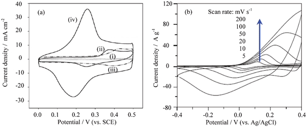 | ||
| Fig. 14 (a) CV curves of various electrodes at 50 mV s−1 in 1 mol l−1 KOH solution: (i) CNTs; (ii), nickel oxide/CNTs; (iii) cobalt oxide/CNTs; (iv), nickel-cobalt oxides/CNTs (Ni/Co molar ratio = 1:1), and (b) CV curves of α-Co(OH)2 composite electrode recorded in 1 mol l−1 KOH aqueous solution at different scan rates (modified from ref. 84a and 85c). | ||
For Co(OH)2, its redox potentials are a little lower than those of Co3O4. However, its reversibility is very good (Fig. 14b).85c Co(OH)2 films (ca. 0.4 mg cm−2) show a specific capacitance of 549 F g−1.85a Nanostructured Co(OH)2 can be prepared into thin film electrodes via screen printing, and their cycling is very good. In 3 mol l−1 KOH solution, 99.69% of its maximum capacity can be retained over 600 cycles.85b The layer structured mesoporous Co(OH)2 presents a good rate capability. When the scan rate is up to 100 mV s−1, the redox peaks in 1 mol l−1 KOH solution can still be clearly identified as shown in Fig. 14b.85c
3.3 Ni(OH)2
Nickel hydroxide is a well-known material in the battery field as a positive electrode in nickel-cadmium and nickel-metal hydride batteries.86a Its actions in the ASC of AC//Ni(OH)2 is similar to that in the batteries and that of Co(OH)2, which is shown in eqn (20):| Ni(OH)2 + OH− ↔ NiOOH + H2O + e− | (20) |
The electrolyte is typically KOH aqueous solutions. Like Co(OH)2, its oxide, NiO, can also be used as a positive electrode for ASCs. However, most reports are related to Ni(OH)2. There are three phases for Ni(OH)2: α, β and γ. Alpha-Ni(OH)2 is unstable in alkaline medium but has a higher theoretic capacitance, and transforms to β-Ni(OH)2, which is more stable.86b In the case of the γ-Ni(OH)2, it is irreversible and could not be used as an electrode material for batteries and ASCs. As a result, without special explanation, Ni(OH)2 usually means the β phase.
To improve its electrochemical performance, heteroatom doping can be used.86c,86d,87–89 For example, Co plays an important role in improving electronic conductivity, and Zn, introduced for higher disordering of the Ni(OH)2 lattice, acts to improve the active material utilization and ion-moving path.88 To increase the specific surface area, nanostructured or porous Ni(OH)2 is preferred.86d
Single Ni(OH)2 hexagonal nanoplates can also form composites with AC,87b,88 CNTs9b,90a and GNSs.90b The CNTs in the composite can reduce the aggregation of Ni(OH)2 nanoparticles and induce a good distribution of the nanosized Ni(OH)2 particles on the cross-linked, netlike CNT structure.90a
The redox behavior of Ni(OH)2 is not very symmetrical, as shown in Fig. 15a.87b The specific capacitances of Ni(OH)2 can be 2217 F g−1, usually higher than that of Co(OH)2.85a When a polymer hydrogel electrolyte from PAAK and 10 mol l−1 KOH solution is used instead of liquid solution, the work voltage can be extended and higher capacitance and a better rate capability can be achieved.90c
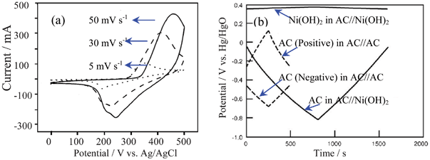 | ||
| Fig. 15 (a) CV curve of Ni(OH)2 in alkaline solution and (b) charge/discharge curves of the positive and negative electrodes in the AC//Ni(OH)2 ASC and electric double layer capacitors of AC//AC at 1 mA cm−2 in 10 mol l−1 KOH aqueous solution (modified from ref. 87b and 90c). | ||
The Co-doped Ni(OH)2 presents a specific capacitances of 684 F g−1, much higher than those of Ni(OH)2 and Co3O4 in 1.0 mol l−1 NaOH solution in the potential range of −0.05–0.5 V (vs. Ag/AgCl), which are about 113 and 161 F g−1 at 5 mV s−1, respectively.86d The simultaneous presence of Zn and Co ions in the Ni(OH)2 layer improves the efficiency of the active material and reduces the resistance of the unit cell.86c The resulting nickel-cobalt hydroxide nanorod arrays on stainless steel achieves a high specific capacitance of 456 F g−1 in 1 mol l−1 KOH solution.
As for composites of Ni(OH)2 with conductive materials, their rate capability is greatly improved due to good electronic conductivity. In addition, the specific capacitance is also increased. In the case of the Ni(OH)2 composite with AC, the AC can act as an electrolyte reservoir to reduce the ionic diffusion resistance, regardless of the charge/discharge current density. As a result, over 160 F g−1 of discharge capacitance can be achieved for Ni(OH)2.87b The composite of Ni(OH)2@CNTs can deliver a capacitance of 311 F g−1 in 6 mol l−1 KOH electrolyte in the potential range of −0.3–0.7 V (vs. SCE).9b Single Ni(OH)2 hexagonal nanoplates on GNSs also show a high specific capacitance (1335 F g−1 at 2.8 A g−1) and remarkable rate capability (953 F g−1 at 45.7 A g−1) in 1 mol l−1 KOH aqueous electrolyte.90b
When Ni(OH)2 and its composites are used as a positive electrode for the ASCs, its energy and power densities are much larger than those of the EDLC. Its typical charge and discharge curves can be shown in Fig. 15b when AC is used as the negative electrode. The ASC from Zn and Co-codoped Ni(OH)2 exhibits a high energy density with 35.7 Wh kg−1, based on the active Ni(OH)2.86c The composite of Ni(OH)2 with MWCNT can deliver an energy of 32 Wh kg−1 at a specific power of 1500 W kg−1 based on the total mass of the active electrode materials. It also exhibits good cycling performance and 90% of its initial capacity is retained for over 2000 cycles.90a
In the case of the α-Ni(OH)2, it can be stabilized by doping. For example, when 7.5% Al is doped, the Al-doped α-Ni(OH)2 materials delivers a high specific capacitance (2.08 × 10³ F g−1) and excellent rate capability.86b Of course, further work is needed for its possible application.
3.4 Intercalation compounds
Intercalation compounds have attracted a lot of interest thanks to their large specific charge. They have been typically used in organic electrolytes but aqueous examples are more interesting.| LiCoO2 ↔ Li1−xCoO2 + xLi+ + xe− (x ≤ 0.5) | (21) |
Its traditional preparation method is via solid-state reaction. In order to get better electrochemical performance, nano structured LiCoO2 has been prepared by sol-gel methods for application in ASCs.5a,42b,9c
CV curves (Fig. 16) of LiCoO2 in a saturated aqueous Li2SO4 solution show that the intercalation and de-intercalation of lithium ions are similar to organic electrolyte solutions.92 There are also three couples of redox peaks for LiCoO2 in the aqueous solution, located at 0.87/0.71, 0.95/0.90 and 1.06/1.01 V (vs. SCE), which agree well with those in the organic electrolyte solution at 4.08/3.83, 4.13/4.03 and 4.21/4.14 V (vs. Li/Li+). The evolution of oxygen (about 1.7 V vs. SCE) in the aqueous electrolyte occurs at much higher potential, indicating the good electrochemical stability of LiCoO2 as the positive electrode of the ASCs. The diffusion coefficient of the lithium ions is of the same magnitude as that in the organic electrolyte; however, the current response and reversibility of redox behavior in the aqueous solution are better than those in the organic electrolytes due to its higher ionic conductivity.93,94
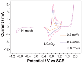 | ||
| Fig. 16 CV curves of LiCoO2 and nickel mesh in saturated Li2SO4 solution (modified from ref. 92). | ||
AC//nano-LiCoO2 in 0.5 mol l−1 Li2SO4 solution at 1 A g−1 between 0–1.8 V shows high capacitance and efficiency. The efficiency of this system increases to nearly 100% after the initial cycle and the capacity does not change much after 40 cycles.94b
Due to the high cost of cobalt, there is not much work on its redox behavior in aqueous solutions.
| LiMn2O4 ↔ Li1−xMn2O4 + xLi+ + xe− (x ≤ 1) | (22) |
The LiMn2O4 spinel can be prepared by solid-state reaction, sol-gel method and hydrothermal methods.5a,42b Among them, one-dimensional (1D) nanostructures including nanowires, nanotubes and nanorods have attracted special attention.9d,10b,99 Porous LiMn2O4 can be prepared by template methods. For example, when PS particles from emulsion polymerization are used as a template, a porous LiMn2O4 consisting of nanograins is conveniently prepared, whose morphology is shown in Fig. 17a.10b To improve the structural stability of LiMn2O4 from solid-state reaction, it can also be doped by heteroatoms such as Al, Cr, Cr–Fe and Ni like in organic electrolytes.100–103
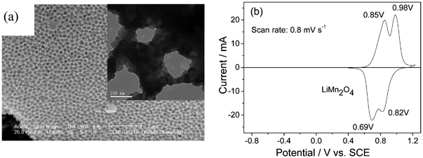 | ||
| Fig. 17 (a) SEM micrograph of the porous LiMn2O4 and (b) CV curve of the micrometer LiMn2O4 in the saturated Li2SO4 solution (modified from ref. 10b and 104). | ||
In the CV curve of LiMn2O4 in the saturated Li2SO4 solution, as shown in Fig. 17b, there are two evident couples of redox peaks at 0.85/0.69 V and 0.98/0.82 V (V vs. SCE), respectively. This agrees well with the de-intercalation and intercalation reactions of Li+ ions in organic electrolytes, which also show two couples of redox peaks. They are also much lower than the potential for oxygen evolution (about 1.7 V vs. SCE) indicating the good stability of LiMn2O4 as the positive electrode for the ASCs in aqueous solutions.104
In the case of porous or nanostructured materials as electrode materials for electrochemical energy storage systems, they have shown some advantages such as higher capacities and better rate capability over traditional micrometer-sized materials.9d,10a,10b,105a For example, LiMn2O4 nanochains exhibit a high reversible capacity of 110 mAh g−1 at 4.5 C and 95 mAh g−1 even at 91 C in 0.5 mol l−1 Li2SO4 aqueous electrolyte. When charged at 136 C, 84% capacity could be obtained.10a
The ASC using micrometer LiMn2O4 as the positive electrode and AC as the negative electrode in a 1 mol l−1 Li2SO4 solution, the specific energy can be 38 Wh kg−1 at a power density of 100 W kg−1, and still keeps 23 Wh kg−1 at a power density of 760 W kg−1 based on the total weight of the active materials of both electrodes.5a In the case of the nanostructured LiMn2O4, when they are assembled into ASCs, power density and cycling behavior are greatly improved. For example, the ASC of AC//LiMn2O4 nanorod presents very high power density in 0.5 mol l−1 Li2SO4, up to 14.5 kW kg−1, and there is still 94% capacity retention after 1200 full cycles.9d,99 The ASC of AC//porous LiMn2O4 in 0.5 mol l−1 Li2SO4 aqueous solution show excellent cycling performance at the rate of 9C (1000 mA g−1), with no more than 7% capacity loss after 10000 cycles.10b The cycling behavior of AC//porous LiMn2O4 is the best amongst the reported LiMn2O4. The nanograins in the porous LiMn2O4 could restrain the Mn3+ on the surface from dissolution, which can also accommodate effectively the strain caused by Jahn–Teller distortion during the charge and discharge process and favor the morphological and structural stability.10b
Doping the micrometer-sized LiMn2O4 with several cations is also a good way to effectively reduce the Jahn–Teller distortion and further improve the cycling stability.105 In the CV curve of LiCr0.15Mn1.85O4 in the saturated aqueous LiNO3 (9 mol l−1) solution, faster “CV response” of LiCr0.15Mn1.85O4 is in correlation with higher capacity retention in comparison to undoped LiMn2O4.100 The Ni-doped LiMn2O4 presents much better rate capability and cycling behavior.103
| Li[Ni(II)]1/3[Co(III)]1/3[Mn(IV)]1/3O2 ↔ Li1−xLi[Ni(III)]1/3[Co(IV)]1/3[Mn(IV)]1/3O2 + xLi+ + xe− | (23) |
The electrochemical stability of LiNi1/3Co1/3Mn1/3O2 in a Li+-containing aqueous solution is critically dependent on the pH value.107 As shown in Fig. 18, one couple of its redox peaks in 2 mol l−1 Li2SO4 solution are situated at 0.48 and 0.68 V (vs. SCE), corresponding to the intercalation and de-intercalation of lithium ions in LiNi1/3Co1/3Mn1/3O2, respectively. The oxygen evolution potential shifts to 1.29 V (vs. SCE), which is much lower than those for LiCoO2 and LiMn2O4 systems. It shows that it is possible to extract lithium ions from the host before the evolution of oxygen.108 However, the CV response and symmetry of the redox peaks are not good.
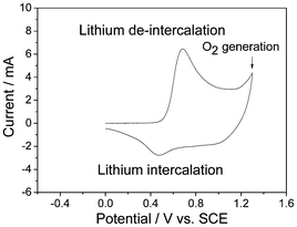 | ||
| Fig. 18 CV curve of in LiNi1/3Co1/3Mn1/3O2 in 2 mol l−1 Li2SO4 aqueous solution (modified from ref. 108). | ||
The cycling performance of LiNi1/3Co1/3Mn1/3O2 is not good, which can not be comparable with that of LiCoO2 or LiMn2O4.93,105c It was believed that the proton intercalation occurred in parallel with Li+ intercalation when the LiNi1/3Co1/3Mn1/3O2 electrode was discharged in neutral solution, which led to serious capacity fading. However, there is no direct evidence. If this is true, then the cycling of LiCoO2 and LiMn2O4 should also be poor, which contradicts the experimental results. In addition, it is curious that LiNi1/3Co1/3Mn1/3O2 synthesized by the sol-gel method can exhibit a good cycling performance in a 2 mol l−1 LiNO3 aqueous solution at different charge/discharge rates from 80 to 200 C in spite of low capacity.109 As a result, further research are needed.
The electrochemical performance of LiNi1/3Mn1/3Co1/3O2 in aqueous solution can be modified by mixing with PPy.110 The redox reversibility and capacity retention are much improved compared to those of the pristine LiNi1/3Mn1/3Co1/3O2. The main reason is that the added PPy could enhance the electronic conductivity of LiNi1/3Mn1/3Co1/3O2 electrode.
In the CV curve of NaMnO2 (Fig. 19a), its shape slightly deviates from the ideal rectangular with two small redox couples, indicative of the pseudocapacitance properties, which are ascribed to the intercalation/de-intercalation of Na+ into and from the solid lattice.10c As for KMnO2 (Fig. 19a), it was found for the first time to present a sharp redox couple at 0.35 and 0.60 V (vs. SCE), which are owned to the intercalation/de-intercalation of K+ into and from the solid lattice.10d Their supercapacitive behaviors can also be observed from their charge and discharge curves in Fig. 19b and Fig. 19c.
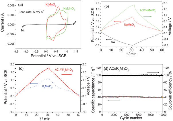 | ||
| Fig. 19 (a) CV curves of NaMnO2 and KxMnO2 in 0.5 mol l−1 Na2SO4 and K2SO4 aqueous solution, charge and discharge curves of (b) AC//AC, NaMnO2 and AC//NaMnO2 hybrid superapacitors in 0.5 mol l−1 Na2SO4 aqueous solution, (c) KxMnO2 and AC//KxMnO2 hybrid supercapacitors in 0.5 mol l−1 K2SO4 aqueous solution, and (d) cycling behavior of the AC//KxMnO2 ASC (modified from ref. 10c and 10d). | ||
The AC//NaMnO2 and AC//KMnO2 ASCs exhibit sloping voltage–time curves in the entire voltage region of 0 to 1.9 V (Fig. 19b and Fig. 19c). They deliver energy densities of 19.5 Wh kg−1 and 25.3 Wh kg−1, respectively, based on the total mass of the active electrode materials and excellent cycling behavior without removal of oxygen in the electrolytes. For example, in the case of AC//KMnO2 ASC, after 10000 full cycles there is no evident capacity fading and the Coulomb efficiency is 100% (Fig. 19d). The latter shows better rate behavior, with an energy density of 17.6 Wh kg−1 at a power density of 2 kW kg−1.10d These ASCs are promising for practical applications because of its low price, easy preparation and excellent cycling behavior.
3.5 Other positive materials
Conductive polymers such as PAn, PPy and polythiophene, which can be p-doped, can also be positive electrodes for ASCs. Their electrochemical performance can be improved by nanostructuring, adding metal oxides such as SnO2, Fe3O4 and TiO2 and conductive materials such as MWCNT.111b Some book chapters5a and reviews16b,16c,16d can be referred, and they will not be expounded here.4. Summary and perspective
In summary, it is clear that the above mentioned electrode materials can build up ASCs of higher energy and power densities in comparison with the traditional EDLCs. For example, the intercalation compounds present some evident advantages over other positive electrodes. The shuttled cations exist originally in the intercalation compounds. During the charge and discharge process, the concentrations of aqueous electrolytes do not change and the ionic conductivities of the electrolytes keep stable. As a result, not only the electrochemical performance can be kept stable during charge and discharge process, but also the amount of electrolytes will be much less than those required for the traditional EDLCs and the other ASCs, leading to higher energy and power densities. To further increase the power density of the ASCs, adding conductive agents, increasing surface area and nano structuring have achieved great advances. To improve their cycling performance, surface modification is an efficient method.The realization of high-efficiency energy storage is one of the greatest scientific and engineering challenges at present, so the design of novel ASCs is an interesting ongoing development and the continued and ever-lasting study is expected. The promising strategies for the further development of advanced electrode materials for ASCs in aqueous electrolytes are generalized as the following:
Both surface and bulk (crystal structure and microstructure) are actively involved in the charge storage process. Designing superior architectures with high surface area and special structure (such as 3D or hierarchical nanostructures, mesoporous, synergetic core-shell structures and ordered nanostructure arrays) are a possible route to maximize the electrochemically active sites for redox reactions or chemical absorption/desorption and to further increase the energy storage density.60a,112a
It is important to investigate the physical/chemical properties of the interface within the ASC structure as well as their effects on the electrochemical performance.114a Challenges remain for understanding the fade mechanisms of various electrodes in aqueous electrolytes. Moreover, theoretical and computational modeling and simulation are also effective in predicting the properties and optimizing the composition of electrode materials used in energy storage systems.2b,114b The combination of theoretical calculations and experimental investigations will promote the exploration of novel high-performance energy storage materials.
It is well understood that by using nanostructured materials, the ion diffusion length is reduced and the inner stress can be alleviated, and thus better rate capability and cyclability can be expected. Electrode materials with mesoporous structures can accommodate large volume changes during the charge/discharge process, and the hollow structures may provide extra space for ion storage.6,112b Hierarchical nanostructures, combining microscale and nanoscale materials, may capitalize on the advantages and restrain the shortcomings of the two components.112c,d Besides, nanostructured current collectors and flexible paper/textile electrodes will gain attention in the future.112e,f Nanostructured current collectors, which have much larger surface areas and good mechanical robustness, can provide both efficient pathways for ion and electron transport through the entire electrode architecture.
There is still some development before the practical applications of ASCs in terms of cycling stabilities. Therefore, it is urgent to improve their overall performance, which depends not only on advanced positive materials but also negative materials.6c,111c The development of new high-performance negative electrode materials is more imminent.
Aqueous electrolytes show promising progress to address the energy challenge for future clean and sustainable energy source. However, the electrolytes for some ASCs are strong acid or alkali,113 which are not environmentally friendly compared to neutral aqueous electrolytes. Electrode materials with high energy density and power density in neutral aqueous electrolytes are desirable. In addition, an appropriate amount of organic additives should be determined because the oxide film may form a few layers of oxide film during the charge and discharge process, which would relieve capacity fading, especially for metal oxides and intercalation compounds.
While tremendous work has been made in the syntheses of various composites for ASCs, a better understanding of how synthesis techniques, composition, and morphology affect the electrochemical performance is also important.115 For some future applications, the development of simple, new and efficient synthesis and fabrication processes are necessary to further improve the practicality of aqueous ASCs towards commercialization. The materials (such as NaxMnO210c and KxMnO210d) prepared by a simple method with low costs have comparable advantages in commercial capacitors.
Acknowledgements
Financial support from MOST (2010DFA61770), STCSM (12JC1401200) and NSFC (21073046) is greatly appreciated.References
- (a) H. Nishide and K. Oyaizu, Science, 2008, 319, 737 CrossRef CAS; (b) J. M. Tarascon and M. Armand, Nature, 2001, 414, 359 CrossRef CAS; (c) J. A. Rogers, T. Someya and Y. G. Huang, Science, 2010, 327, 1603 CrossRef CAS; (d) F. Meng and Y. Ding, Adv. Mater., 2011, 23, 4098 CrossRef CAS; (e) P. Simon and Y. Gogotsi, Nat. Mater., 2008, 7, 845 CrossRef CAS.
- (a) B. E. Conway, Electrochemical Supercapacitors: Scientific Fundamentals and Technological Applications, Plenum Publishers, New York, 1999 Search PubMed; (b) S. N. Razumov, A. Klementov, S. Litvinenko and A. Beliakov, U. S. Patent No. 6,222,723 ( 2001) Search PubMed; (c) D. Cericola and R. Kötz, Electrochim. Acta, 2012, 72, 1 CrossRef CAS; (d) M. S. Hong, S. H. Lee and S. W. Kim, Electrochem. Solid-State Lett., 2002, 5, A227 CrossRef CAS.
- H. Nishihara and T. Kyotani, Adv. Mater., 2012, 24, 4473 CrossRef CAS.
- (a) W. Li, W. R. McKinnon and J. R. Dahn, J. Electrochem. Soc., 1994, 141, 2310 CrossRef CAS; (b) Q. Wang, Z. Wen and J. Li, Adv. Funct. Mater., 2006, 16, 2141 CrossRef CAS; (c) H. J. Liu, W. J. Cui, L. H. Jin, C. X. Wang and Y. Y. Xia, J. Mater. Chem., 2009, 19, 3661 RSC; (d) R. Ruffo, F. L. Mantia, C. Wessells, R. A. Huggins and Y. Cui, Solid State Ionics, 2011, 192, 289 CrossRef CAS; (e) H. Manjunatha, G. S. Suresh and T. V. Venkatesha, J. Solid State Electrochem., 2011, 15, 431 CrossRef CAS.
- (a) Z. B. Wen, S. Tian, L. L. Liu and Y. P. Wu, Chapter 13 Controlled particle size and shape of nanomaterials and their applications in supercapacitors, in Controlled Size and Shape of Nanostructured Materials and Their Applications, pp. 473–519, Pan Stanford Publishing Pte Ltd, Singapore, 2012 Search PubMed; (b) K. Xie, X. T. Qin, X. Z. Wang, Y. N. Wang, H. S. Tao, Q. Wu, L. J. Yang and Z. Hu, Adv. Mater., 2012, 24, 347 CrossRef CAS; (c) L. L. Zhang and X. S. Zhao, Chem. Soc. Rev., 2009, 38, 2520 RSC; (d) Y. Zhai, Y. Dou, D. Zhao, P. F. Fulvio, R. T. Mayes and S. Dai, Adv. Mater., 2011, 23, 4828 CrossRef CAS.
- (a) Q. T. Qu, Y. Shi, L. L. Li, W. L. Guo, Y. P. Wu, H. P. Zhang, S. Y. Guan and R. Holze, Electrochem. Commun., 2009, 11, 1325 CrossRef CAS; (b) Q. T. Qu, Y. S. Zhu, X. W. Gao and Y. P. Wu, Adv. Energy Mater., 2012, 2, 950 CrossRef CAS; (c) W. Tang, L. Liu, S. Tian, L. Li, Y. Yue, Y. P. Wu and K. Zhu, Chem. Commun., 2011, 47, 10058 RSC; (d) Y. G. Wang, Z. D. Wang and Y. Y. Xia, Electrochim. Acta, 2005, 50, 5641 CrossRef CAS; (e) M. C. Liu, L. Bin Kong, C. Lu, X. M. Li, Y. C. Luo and L. Kang, RSC Adv., 2012, 2, 1890 RSC; (f) Z. Chen, D. Weng, H. Sohn, M. Cai and Y. Lu, RSC Adv., 2012, 2, 1755 RSC.
- (a) T. Brousse, P. L. Taberna, O. Crosnier, R. Dugas, P. Guillemet, Y. Scudeller, Y. Zhou, F. Favier, D. Belanger and P. Simon, J. Power Sources, 2007, 173, 633 CrossRef CAS; (b) Y. T. Wang, A. H. Lu and W. C. Li, Microporous Mesoporous Mater., 2012, 153, 247 CrossRef CAS; (c) Q. T. Qu, P. Zhang, B. Wang, Y. H Chen, S. Tian, Y. P. Wu and R. Holze, J. Phys. Chem. C, 2009, 113, 14020 CrossRef CAS; (d) W. Tang, Y. Y. Hou, X. J. Wang, Y. Bai, Y. S. Zhu, H. Sun, Y. B. Yue, Y. P. Wu, K. Zhu and R. Holze, J. Power Sources, 2012, 197, 330 CrossRef CAS.
- (a) G. Yu, L. Hu, M. Vosgueritchian, H. Wang, X. Xie, J. R. McDonough, X. Cui, Y. Cui and Z. Bao, Nano Lett., 2011, 11, 2905 CrossRef CAS; (b) Z. Fan, J. Yan, T. Wei, L. Zhi, G. Ning, T. Li and F. Wei, Adv. Funct. Mater., 2011, 21, 2366 CrossRef CAS; (c) Z. S. Wu, W. Ren, D. W. Wang, F. Li, B. Liu and H. M. Cheng, ACS Nano, 2010, 4, 5835 CrossRef CAS; (d) N. Yu and L. Gao, Electrochem. Commun., 2009, 11, 220 CrossRef CAS.
- (a) P. Perret, Z. Khani, T. Brousse, D. Bélanger and D. Guay, Electrochim. Acta, 2011, 56, 8122 CrossRef CAS; (b) X. F. Wang, D. B. Ruan and Z. Yu, Trans. Nonferrous Met. Soc. China, 2006, 16, 1129 CrossRef CAS; (c) W. Tang, L. L. Liu, S. Tian, L. Li, Y. B. Yue, Y. P. Wu, S. Y. Guan and K. Zhu, Electrochem. Commun., 2010, 12, 1524 CrossRef CAS; (d) W. Tang, L. L. Li, S. Tian, L. Li, L. L. Li, Y. B. Yue, Y. Bai, Y. P. Wu, K. Zhu and R. Holze, Electrochem. Commun., 2011, 13, 1159 CrossRef CAS.
- (a) W. Tang, S. Tian, L. L. Liu, L. Li, H. P. Zhang, Y. B. Yue, Y. Bai, Y. P. Wu and K. Zhu, Electrochem. Commun., 2011, 13, 205 CrossRef CAS; (b) Q. T. Qu, L. J. Fu, X. Y. Zhan, D. Samuelis, J. Maier, L. Li, S. Tian, Z. H. Li and Y. P. Wu, Energy Environ. Sci., 2011, 4, 3985 RSC; (c) Q. T. Qu, Y. Shi, S. Tian, Y. H. Chen, Y. P. Wu and R. Holze, J. Power Sources, 2009, 194, 1222 CrossRef CAS; (d) Q. T. Qu, L. Li, S. Tian, W. Guo, Y. P. Wu and R. Holze, J. Power Sources, 2010, 195, 2789 CrossRef CAS.
- (a) M. M. Titirici and M. Antonietti, Chem. Soc. Rev., 2010, 39, 103 RSC; (b) M. Endo, Y. J. Kim, H. Ohta, K. Ishii, T. Inoue, T. Hayashi, Y. Nishimura, T. Maeda and M. S. Dresselhaus, Carbon, 2002, 40, 2613 CrossRef CAS; (c) D. L. Castello, D. C. Amoros, A. L. Solano, S. Shiraishi, H. Kurihara and A. Oya, Carbon, 2003, 41, 1765 CrossRef.
- (a) D. Qu, J. Power Sources, 2002, 109, 403 CrossRef CAS; (b) E. Raymundo-Pinero, K. Kierzek, J. Machnikowski and F. Beguin, Carbon, 2006, 44, 2498 CrossRef CAS.
- Q. T. Qu, B. Wang, L. C. Yang, Y. Shi, S. Tian and Y. P. Wu, Electrochem. Commun., 2008, 10, 1652 CrossRef CAS.
- (a) R. N. Reddy and R. G. Reddy, J. Power Sources, 2003, 124, 330 CrossRef CAS; (b) H. Inoue, T. Morimoto and S. Nohara, Electrochem. Solid-State Lett., 2007, 10, A261 CrossRef CAS.
- (a) R. H. Baughman, A. A. Zakhidov and W. A. D. Heer, Science, 2002, 297, 787 CrossRef CAS; (b) C. Du and N. Pan, J. Power Sources, 2006, 160, 1487 CrossRef CAS.
- (a) Y. P. Wu, E. Rahm and R. Holze, J. Power Sources, 2003, 114, 228 CrossRef CAS; (b) G. P. Wang, L. Zhang and J. J. Zhang, Chem. Soc. Rev., 2012, 41, 797 RSC; (c) G. A. Snook, P. Kao and A. S. Best, J. Power Sources, 2011, 196, 1 CrossRef CAS; (d) H. Pan, J. Y. Li and Y. P. Feng, Nanoscale Res. Lett., 2010, 5, 654 CrossRef CAS; (e) Y. P. Wu, E. Rahm and R. Holze, Electrochim. Acta, 2002, 47, 3491 CrossRef CAS.
- (a) T. Chen, Z. Cai, Z. Yang, L. Li, X. Sun, T. Huang, A. Yu, H. G. Kia and H. Peng, Adv. Mater., 2011, 23, 4620 CrossRef CAS; (b) Y. Fang, F. Jiang, H. Liu, X. Wu and Y. Lu, RSC Adv., 2012, 2, 6562 RSC; (c) E. Frackowiak and F. Beguin, Carbon, 2002, 40, 1775 CrossRef CAS.
- (a) C. G. Liu, M. Liu, F. Li and H. M. Cheng, Appl. Phys. Lett., 2008, 92, 143108 CrossRef; (b) K. H. An, W. S. Kim, Y. S. Park, J. M. Moon, D. J. Bae, S. C. Lim, Y. S. Lee and Y. H. Lee, Adv. Funct. Mater., 2001, 11, 387 CrossRef CAS.
- Y. Huang, J. Liang and Y. Chen, Small, 2012, 8, 1805 CrossRef CAS.
- K. S. Novoselov, A. K. Geim, S. V. Morozov, D. Jiang, Y. Zhang, S. V. Dubonos, I. V. Grigorieva and A. A. Firsov, Science, 2004, 306, 666 CrossRef CAS.
- C. N. R. Rao, A. K. Sood, K. S. Subrahmanyam and A. Govindaraj, Angew. Chem., Int. Ed., 2009, 48, 7752 CrossRef CAS.
- (a) Y. Sun, Q. Wu and G. Shi, Energy Environ. Sci., 2011, 4, 1113 RSC; (b) D. A. C. Brownson, D. K. Kampouris and C. E. Banks, J. Power Sources, 2011, 196, 4873 CrossRef CAS; (c) S. Bai and X. Shen, RSC Adv., 2012, 2, 64 RSC.
- (a) Y. Hernandez, V. Nicolosi, M. Lotya, F. M. Blighe, Z. Y. Sun, S. De, I. T. McGovern, B. Holland, M. Byrne, Y. K. Gunko, J. bJ. Boland, P. Niraj, G. Duesberg, S. Krishnamurthy, R. Goodhue, J. Hutchison, V. Scardaci, A. C. Ferrari and J. N. Coleman, Nat. Nanotechnol., 2008, 3, 563 CrossRef CAS; (b) C. E. Hamilton, J. R. Lomeda, Z. Z. Sun, J. M. Tour and A. R. Barron, Nano Lett., 2009, 9, 3460 CrossRef CAS.
- S. Park and R. S. Ruoff, Nat. Nanotechnol., 2009, 4, 217 CrossRef CAS.
- D. A. Dikin, S. Stankovich, E. J. Zimney, R. D. Piner, G. H. B. Dommett, G. Evmenenko, S. T. Nguyen and R. S. Ruoff, Nature, 2007, 448, 457 CrossRef CAS.
- (a) D. Li, M. B. Muller, S. Gilje, R. B. Kaner and G. G. Wallace, Nat. Nanotechnol., 2008, 3, 101 CrossRef CAS; (b) M. Lotya, Y. Hernandez, P. J. King, R. J. Smith, V. Nicolosi, L. S. Karlsson, F. M. Blighe, S. De, Z. M. Wang, I. T. M. Govern, G. S. Duesberg and J. N. Coleman, J. Am. Chem. Soc., 2009, 131, 3611 CrossRef CAS; (c) S. Stankovich, D. A. Dikin, R. D. Piner, K. A. Kohlhaas, A. Kleinhammes, Y. Jia, Y. Wu, S. T. Nguyen and R. S. Ruoff, Carbon, 2007, 45, 1558 CrossRef CAS; (d) H. L. Guo, X. F. Wang, Q. Y. Qian, F. B. Wang and X. H. Xia, ACS Nano, 2009, 3, 2653 CrossRef CAS.
- A. K. Geim and K. S. Novoselov, Nat. Mater., 2007, 6, 183 CrossRef CAS.
- T. Kuila, S. Bose, A. K. Mishra, P. Khanra, N. H. Kim and J. H. Lee, Prog. Mater. Sci., 2012, 57, 1061 CrossRef CAS.
- X. Zhao, L. Zhang, S. Murali, M. D. Stoller, Q. Zhang, Y. Zhu and R. S. Ruoff, ACS Nano, 2012, 6, 5404 CrossRef CAS.
- L. Zhang and G. Q. Shi, J. Phys. Chem. C, 2011, 115, 17206 CAS.
- D. R. Rolison, J. W. Long, J. C. Lytle, A. E. Fischer, C. P. Rhodes, T. M. McEvoy, M. E. Bourg and A. M. Lubers, Chem. Soc. Rev., 2009, 38, 226 RSC.
- (a) B. G. Choi, M. H. Yang, W. H. Hong, J. W. Choi and Y. S. Huh, ACS Nano, 2012, 6, 4020 CrossRef CAS; (b) G. Q. Ning, Z. J. Fan, G. Wang, J. S. Gao, W. Z. Qian and F. Wei, Chem. Commun., 2011, 47, 5976 RSC.
- S. H. Lee, H. W. Kim, J. O. Hwang, W. J. Lee, J. Kwon, C. W. Bielawski, R. S. Ruoff and S. O. Kim, Angew. Chem., Int. Ed., 2010, 49, 10084 CrossRef CAS.
- X. Lu, H. Dou, B. Gao, C. Yuan, S. Yang, L. Hao, L. Shen and X. Zhang, Electrochim. Acta, 2011, 56, 5115 CrossRef CAS.
- (a) S. Stankovich, D. A. Dikin, G. H. B. Dommett, K. M. Kohlhaas, E. J. Zimney, E. A. Stach, R. D. Piner, S. T. Nguyen and R. S. Ruoff, Nature, 2006, 442, 282 CrossRef CAS; (b) J. Liu, J. An, Y. Zhou, Y. Ma, M. Li, M. Yu and S. Li, ACS Appl. Mater. Interfaces, 2012, 4, 2870 CrossRef CAS; (c) Q. Wu, Y. I. Xu, Z. Yao, A. Liu and G. Shi, ACS Nano, 2010, 4, 1963 CrossRef CAS; (d) N. A. Kumar, H. J. Choi, Y. R. Shin, D. W. Chang, L. Dai and J. B. Baek, ACS Nano, 2012, 6, 1715 CrossRef CAS; (e) P. Si, S. Ding, X. W. Lou and D. H. Kim, RSC Adv., 2011, 1, 1271 RSC; (f) S. H. Aboutalebi, A. T. Chidembo, M. Salari, K. Konstantinov, D. Wexler, H. K. Liu and S. X. Dou, Energy Environ. Sci., 2011, 4, 1855 RSC.
- Z. Liu, S. W. Tay and X. Li, Chem. Commun., 2011, 47, 12473 RSC.
- M. Sathiya, A. S. Prakash, K. Ramesha, J. M. Tarascon and A. K. Shukla, J. Am. Chem. Soc., 2011, 133, 16291 CrossRef CAS.
- M. S. Whittingham, Chem. Rev., 2004, 104, 4271 CrossRef CAS.
- Y. Wei, C. W. Ryu and K. B. Kim, J. Alloys Compd., 2008, 459, L13 CrossRef CAS.
- X. Rui, J. Zhu, W. Liu, H. Tan, D. Sim, C. Xu, H. Zhang, J. Ma, H. H. Hng, T. M. Lim and Q. Yan, RSC Adv., 2011, 1, 117 RSC.
- G. Du, K. H. Seng, Z. Guo, J. Liu, W. Li, D. Jia, C. Cook, Z. Liu and H. Liu, RSC Adv., 2011, 1, 690 RSC.
- (a) T. Zhai, H. Liu, H. Li, X. Fang, M. Liao, L. Li, H. Zhou, Y. Koide, Y. Bando and D. Golberg, Adv. Mater., 2010, 22, 2547 CrossRef CAS; (b) L. J. Fu, H. Liu, Y. P. Wu, E. Rahm, R. Holze and H. Q. Wu, Prog. Mater. Sci., 2005, 50, 881 CrossRef CAS.
- Z. Chen, Y. Qin, D. Weng, Q. Xiao, Y. Peng, X. Wang, H. Li, F. Wei and Y. Lu, Adv. Funct. Mater., 2009, 19, 3420 CrossRef CAS.
- W. Tang, X. Gao, Y. Zhu, Y. Yue, Y. Shi, Y. P. Wu and K. Zhu, J. Mater. Chem., 2012, 22, 20143 RSC.
- (a) T. Sumura and M. Inagaki, Solid State Ionics, 1997, 104, 183 CrossRef; (b) T. Brezesinski, J. Wang, S. H. Tolbert and B. Dunn, Nat. Mater., 2010, 9, 146 CrossRef CAS.
- H. Farsi, F. Gobal, H. Raissi and S. Moghiminia, J. Solid State Electrochem., 2010, 14, 643 CrossRef CAS.
- I. Shakir, M. Shahid, H. W. Yang and D. J. Kang, Electrochim. Acta, 2010, 56, 376 CrossRef CAS.
- G. R. Li, Z. L. Wang, F. L. Zheng, Y. N. Ou and Y. X. Tong, J. Mater. Chem., 2011, 21, 4217 RSC.
- (a) J. Hu, A. Ramadan, F. Luo, B. Qi, X. Deng and J. Chen, J. Mater. Chem., 2011, 21, 15009 RSC; (b) T. Tao, Q. Y. Chen, H. P. Hu and Y. Chen, Mater. Lett., 2012, 66, 102 CrossRef CAS; (c) W. Tang, L. L. Liu, Y. S. Zhu, H. Sun, Y. P. Wu and K. Zhu, Energy Environ. Sci., 2012, 5, 6909 RSC.
- (a) J. H. Park and O. O. Park, J. Power Sources, 2002, 111, 185 CrossRef CAS; (b) F. K. Cheng, C. He, D. Shu, H. Y. Chen, J. Zhang, S. Q. Tang and D. E. Finlow, Mater. Chem. Phys., 2011, 131, 268 CrossRef CAS; (c) K. Kvastek and V. Horvat-Radosevic, J. Electroanal. Chem., 2001, 511, 65 CrossRef CAS.
- (a) J. J. Niu, W. G. Pell and B. E. Conway, J. Power Sources, 2006, 156, 725 CrossRef CAS; (b) Z. B. Wen, Q. T. Qu, Q. Gao, Z. H. Hu, Y. P. Wu, X. W. Zheng, Y. F. Liu and X. J. Wang, Electrochem. Commun., 2009, 11, 715 CrossRef CAS; (c) C. W. Huang, C. T. Hsieh, P. L. Kuo and H. Teng, J. Mater. Chem., 2012, 22, 7314 RSC.
- (a) S. W. Lee, B. S. Kim, S. Chen, Y. S. Horn and P. T. Hammond, J. Am. Chem. Soc., 2009, 131, 671 CrossRef CAS; (b) K. Esumi, M. Ishigami, A. Nakajima, K. Sawada and H. Honda, Carbon, 1996, 34, 279 CrossRef CAS; (c) T. Ramanathan, F. T. Fisher, R. S. Ruoff and L. C. Brinson, Chem. Mater., 2005, 17, 1290 CrossRef CAS; (d) Y. Y. Shao, J. Wang, M. Engelhard, C. M. Wan and Y. H. Lin, J. Mater. Chem., 2010, 20, 743 RSC.
- (a) Y. T. Kim and T. Mitani, J. Power Sources, 2006, 158, 1517 CrossRef CAS; (b) D. N. Futaba, K. Hata, T. Yamada, T. Hiraoka, Y. Hayamizu, Y. Kakudate, O. Tanaike, H. Hatori, M. Yumura and S. Iijima, Nat. Mater., 2006, 5, 987 CrossRef CAS.
- (a) C. C. Hu, K. H. Chang, M. C. Lin and Y. T. Wu, Nano Lett., 2006, 6, 2690 CrossRef CAS; (b) B. O. Park, C. D. Lokhande, H. S. Park, K. D. Jung and O. S. Joo, J. Power Sources, 2004, 134, 148 CrossRef CAS; (c) W. Sugimoto, T. Shibutani, Y. Murakami and Y. Takasu, Electrochem. Solid-State Lett., 2002, 5, A170 CrossRef CAS; (d) C. C. Hu, H. Y. Guo, K. H. Chang and C. C. Huang, Electrochem. Commun., 2009, 11, 1631 CrossRef CAS.
- Y. Su, F. Wu, L. Bao and Z. Yang, New Carbon Mater., 2007, 22, 53 CrossRef CAS.
- H. Li, R. Wang and R. Cao, Microporous Mesoporous Mater., 2008, 111, 32 CrossRef CAS.
- P. C. Chen, G. Shen, Y. Shi, H. Chen and C. Zhou, ACS Nano, 2010, 4, 4403 CrossRef CAS.
- (a) Y. T. Kim, K. Tadai and T. Mitani, J. Mater. Chem., 2005, 15, 4914 RSC; (b) J. S. Ye, H. F. Cui, X. Liu, T. M. Lim, W. D. Zhang and F. S. Sheu, Small, 2005, 1, 560 CrossRef CAS; (c) W. C. Fang, O. Chyan, C. L. Sun, C. T. Wu, C. P. Chen, K. H. Chen, L. C. Chen and J. H. Huang, Electrochem. Commun., 2007, 9, 239 CrossRef CAS; (d) R. K. Das, B. Liu, J. R. Reynolds and A. G. Rinzler, Nano Lett., 2009, 9, 677 CrossRef CAS.
- (a) Z. S. Wu, D. W. Wang, W. Ren, J. Zhao, G. Zhou, F. Li and H. M. Cheng, Adv. Funct. Mater., 2010, 20, 3595 CrossRef CAS; (b) Z. Algharaibeh, X. Liu and P. G. Pickup, J. Power Sources, 2009, 187, 640 CrossRef CAS.
- (a) W. Wei, X. Cui, W. Chen and D. Ivey, Chem. Soc. Rev., 2011, 40, 1697 RSC; (b) M. S. Hong, S. H. Lee and S. W. Kim, Electrochem. Solid-State Lett., 2002, 5, A227 CrossRef CAS; (c) V. Khomenko, E. R. Pinero and F. Béguin, J. Power Sources, 2006, 153, 183 CrossRef CAS.
- (a) H. A. Mosqueda, O. Crosnier, L. Athouël, Y. Dandeville, Y. Scudeller, P. Guillemet, D. M. Schleich and T. Brousse, Electrochim. Acta, 2010, 55, 7479 CrossRef CAS; (b) S. Li, L. Qi, L. Lu and H. Wang, RSC Adv., 2012, 2, 6741 RSC.
- (a) M. Xu, L. Kong, W. Zhou and H. Li, J. Phys. Chem. C, 2007, 111, 19141 CrossRef CAS; (b) H. Jiang, C. Z. Li, T. Sun and J. Ma, Chem. Commun., 2012, 48, 2606 RSC.
- G. R. Li, Z. P. Feng, Y. N. Ou, D. C. Wu, R. W. Fu and Y. X. Tong, Langmuir, 2010, 26, 2209 CrossRef CAS.
- A. Yuan and Q. Zhang, Electrochem. Commun., 2006, 8, 1173 CrossRef CAS.
- L. Bao, J. Zang and X. Li, Nano Lett., 2011, 11, 1215 CrossRef CAS.
- H. Zhang, G. P. Cao, Z. Y. Wang, Y. S. Yang, Z. J. Shi and Z. N. Gu, Nano Lett., 2008, 8, 2664 CrossRef CAS.
- K. S. Kim and S. J. Park, J. Solid State Electrochem., 2012, 16, 2751 CrossRef CAS.
- J. Yan, T. Wei, W. M. Qiao, Z. J. Fan, L. J. Zhang, T. Y. Li and Q. K. Zhao, Electrochem. Commun., 2010, 12, 1279 CrossRef CAS.
- Q. Cheng, J. Tan, J. Ma, H. Zhang, N. Shinya and L. C. Qin, Carbon, 2011, 49, 2917 CrossRef CAS.
- Y. Hou, Y. Cheng, T. Hobson and J. Liu, Nano Lett., 2010, 10, 2727 CrossRef CAS.
- S. Dong, X. Chen, L. Gu, X. Zhou, L. Li, Z. Liu, P. Han, H. Xu, J. Yao, H. Wang, X. Zhang, C. Shang, G. Cui and L. Chen, Energy Environ. Sci., 2011, 4, 3502 CAS.
- X. Lang, A. Hirata, T. Fujita and M. Chen, Nat. Nanotechnol., 2011, 6, 232 CrossRef CAS.
- M. Toupin, T. Brousse and D. Belanger, Chem. Mater., 2004, 16, 3184 CrossRef CAS.
- B. Djurfors, J. N. Broughton, M. J. Brett and D. G. Ivey, J. Mater. Sci., 2003, 38, 4817 CrossRef CAS.
- B. Djurfors, J. N. Broughton, M. J. Brett and D. G. Ivey, Acta Mater., 2005, 53, 957 CrossRef CAS.
- A. J. Roberts and R. C. T. Slade, Electrochim. Acta, 2010, 55, 7460 CrossRef CAS.
- (a) Y. Cheng, S. Lu, H. Zhang, C. V. Varanasi and J. Liu, Nano Lett., 2012, 12, 4206 CrossRef CAS; (b) A. Yuan, X. Wang, Y. Wang and J. Hu, Energy Convers. Manage., 2010, 51, 2588 CrossRef CAS; (c) L. Demarconnay, E. R. Pinero and F. Béguin, J. Power Sources, 2011, 196, 580 CrossRef CAS; (d) L. Zhou, L. C. Yang, P. Yuan, J. Zou, Y. P. Wu and C. Z. Yu, J. Phys. Chem. C, 2010, 114, 21868 CrossRef CAS.
- (a) R. N. Reddy and R. G. Reddy, J. Power Sources, 2006, 156, 700 CrossRef CAS; (b) I. Stojkovic, N. Cvjeticanin, I. Pašti, M. Mitric and S. Mentus, Electrochem. Commun., 2009, 11, 1512 CrossRef CAS.
- (a) D. Li and Y. Xia, Nano Lett., 2003, 3, 555 CrossRef CAS; (b) G. Wee, H. Z. Soh, Y. L. Cheah, S. G. Mhaisalkar and M. Srinivasan, J. Mater. Chem., 2010, 20, 6720 RSC; (c) D. Sun, C. W. Kwon, G. Baure, E. Richman, J. Maclean, B. Dunn and S. H. Tolbert, Adv. Funct. Mater., 2004, 14, 1197 CrossRef CAS; (d) L. M. Chen, Q. Y. Lai, Y. J. Hao, Y. Zhao and X. Y. Ji, J. Alloys Compd., 2009, 467, 465 CrossRef CAS.
- (a) L. Yu, C. X. Zhao, X. Long and W. Chen, Microporous Mesoporous Mater., 2009, 126, 58 CrossRef CAS; (b) W. C. Fang, J. Phys. Chem. C, 2008, 112, 11552 CrossRef CAS; (c) M. Jayalakshmi, M. M. Rao, N. Venugopal and K. B. Kim, J. Power Sources, 2007, 166, 578 CrossRef CAS; (d) Y. Yang, D. Kim, M. Yang and P. Schmuki, Chem. Commun., 2011, 47, 7746 RSC.
- (a) L. T. Lam and R. Louey, J. Power Sources, 2006, 158, 1140 CrossRef CAS; (b) P. K. Shen and X. L. Wei, Electrochim. Acta, 2003, 48, 1743 CrossRef CAS.
- (a) N. Yu, L. Gao, S. Zhao and Z. Wang, Electrochim. Acta, 2009, 54, 3835 CrossRef CAS; (b) P. N. Bartlett, T. Dunford and M. A. Ghanem, J. Mater. Chem., 2002, 12, 3130 RSC; (c) L. X. Ding, F. L. Zheng, J. W. Wang, G. R. Li, Z. L. Wang and Y. X. Tong, Chem. Commun., 2012, 48, 1275 RSC.
- (a) S. G. Kandalkar, D. S. Dhawale, C. K. Kim and C. D. Lokhande, Synth. Met., 2010, 160, 1299 CrossRef CAS; (b) R. Tummala, R. K. Guduru and P. S. Mohanty, J. Power Sources, 2012, 209, 44 CrossRef CAS; (c) L. Y. Gong, X. H. Liu, L. H. Su and L. Q. Wang, J. Solid State Electrochem., 2012, 16, 297 CrossRef CAS.
- (a) Z. Fan, J. H. Chen, K. Z. Cui, F. Sun, Y. Xu and Y. F. Kuang, Electrochim. Acta, 2007, 52, 2959 CrossRef CAS; (b) J. Yan, T. Wei, W. M. Qiao, B. Shao, Q. K. Zhao, L. J. Zhang and Z. J. Fan, Electrochim. Acta, 2010, 55, 6973 CrossRef CAS; (c) X. W. Wang, S. Q. Liu, H. Y. Wang, F. Y. Tu, D. Fang and Y. H. Li, J. Solid State Electrochem., 2012, 16, 3593 CrossRef CAS.
- (a) C. C. Hu, J. C. Chen and K. H. Chang, J. Power Sources, 2013, 221, 128 CrossRef CAS; (b) X. B. Ji, P. M. Hallam, S. M. Houssein, R. Kadara, L. M. Lang and C. E. Banks, RSC Adv., 2012, 2, 1508 RSC; (c) J. M. Ko, D. Soundarajan, J. H. Park, S. D. Yang, S. W. Kim, K. M. Kim and K. H. Yu, Curr. Appl. Phys., 2012, 12, 341 CrossRef.
- (a) U. Kohler, C. Antonius and P. Bauerlein, J. Power Sources, 2004, 127, 45 CrossRef CAS; (b) J. W. Lang, L. B. Kong, M. Liu, Y. C. Luo and L. Kang, J. Solid State Electrochem., 2010, 14, 1533 CrossRef CAS; (c) J. H. Park, S. W. Kim, O. O. Park and J. M. Ko, Appl. Phys. A: Mater. Sci. Process., 2006, 82, 593 CrossRef CAS; (d) J. H. Zhong, A. L. Wang, G. R. Li, J. W. Wang, Y. N. Ou and Y. X. Tong, J. Mater. Chem., 2012, 22, 5656 RSC.
- (a) G. P. Wang, L. Zhang, J. Kim and J. J. Zhang, J. Power Sources, 2012, 217, 554 CrossRef CAS; (b) J. H. Park, O. O. Park, K. H. Shin, C. S. Jin and J. H. Kim, Electrochem. Solid-State Lett., 2002, 5, H7 CrossRef CAS.
- J. H. Park, S. W. Kim, O. Park and J. M. Ko, Appl. Phys. A: Mater. Sci. Process., 2006, 82, 593 CrossRef CAS.
- R. R. Salunkhe, K. Jang, S. W. Lee and H. Ahn, RSC Adv., 2012, 2, 3190 RSC.
- (a) Y. G. Wang, L. Yu and Y. Y. Xia, J. Electrochem. Soc., 2006, 153, A743 CrossRef CAS; (b) H. Wang, H. S. Casalongue, Y. Liang and H. Dai, J. Am. Chem. Soc., 2010, 132, 7472 CrossRef CAS; (c) S. Nohara, T. Asahina, H. Wada, N. Furukawa, H. Inoue, N. Sugoh, H. Iwasaki and C. Iwakura, J. Power Sources, 2006, 157, 605 CrossRef CAS.
- (a) Y. G. Wang, J. Y. Luo, C. X. Wang and Y. Y. Xia, J. Electrochem. Soc., 2006, 153, A1425 CrossRef CAS; (b) W. Tang, L. L. Liu, S. Tian, L. Li, Y. B. Yue, Y. P. Wu, S. Y. Guan and K. Zhu, Electrochem. Commun., 2010, 12, 1524 CrossRef CAS.
- G. J. Wang, Q. T. Qu, B. Wang, Y. Shi, S. Tian, Y. P. Wu and R. Holze, Electrochim. Acta, 2009, 54, 1199 CrossRef CAS.
- G. J. Wang, L. J. Fu, N. H. Zhao, L. C. Yang, Y. P. Wu and H. Q. Wu, Angew. Chem., Int. Ed., 2007, 46, 295 CrossRef CAS.
- (a) G. J. Wang, L. C. Yang, Q. T. Qu, B. Wang, Y. P. Wu and R. Holze, J. Solid State Electrochem., 2010, 14, 865 CrossRef CAS; (b) M. Winter, J. O. Besenhard, M. E. Spahr and P. Novák, Adv. Mater., 1998, 10, 725 CrossRef CAS.
- Y. P. Wu, X. Y. Yuan, C. Dong and J. Y. Duan, Lithium Ion Batteries: Practice and Applications (2nd Edi.), Chemical Industry Press, Beijing, 2012 Search PubMed.
- (a) K. M. Shaju and P. G. Bruce, Chem. Mater., 2008, 20, 5557 CrossRef CAS; (b) F. Jiao, J. L. Bao, A. H. Hill and P. G. Bruce, Angew. Chem., Int. Ed., 2008, 47, 9711 CrossRef CAS.
- (a) W. Li, J. R. Dahn and D. Wainwright, Science, 1994, 264, 1115 CAS; (b) W. Li and J. R. Dahn, J. Electrochem. Soc., 1995, 142, 1472 Search PubMed.
- M. J. Zhang and J. R. Dahn, J. Electrochem. Soc., 1996, 143, 2730 CrossRef CAS.
- M. Zhao, X. Song, F. Wang, W. Dai and X. Lu, Electrochim. Acta, 2011, 56, 5673 CrossRef CAS.
- I. B. Stojkovic, N. D. Cvjeticanin and S. V. Mentus, Electrochem. Commun., 2010, 12, 371 CrossRef CAS.
- A. Yuan, L. Tian, W. Xu and Y. Wang, J. Power Sources, 2010, 195, 5032 CrossRef CAS.
- W. Xu, A. Yuan and Y. Wang, J. Solid State Electrochem., 2012, 16, 429 CrossRef CAS.
- F. X. Wang, S. Y. Xiao, Y. Shi, L. L. Liu, Y. S. Zhu, Y. P. Wu, J. Z. Wang and R. Holze, Electrochim. Acta, 2013, 93, 301 CrossRef CAS.
- G. J. Wang, Q. T. Qu, B. Wang, Y. Shi, S. Tian and Y. P. Wu, ChemPhysChem, 2008, 9, 2299 CrossRef CAS.
- (a) L. Tian and A. Yuan, J. Power Sources, 2009, 192, 693 CrossRef CAS; (b) N. Cvjeticanin, I. Stojkovic, M. Mitric and S. Mentus, J. Power Sources, 2007, 174, 1117 CrossRef CAS; (c) G. J. Wang, H. P. Zhang, L. J. Fu, B. Wang and Y. P. Wu, Electrochem. Commun., 2007, 9, 1873 CrossRef CAS.
- L. Liu, F. Tian, X. Wang, Z. Yang, Q. Chen and X. Wang, J. Solid State Electrochem., 2012, 16, 491 CrossRef CAS.
- Y. G. Wang, J. Y. Lou, W. Wu, C. X. Wang and Y. Y. Xia, J. Electrochem. Soc., 2007, 154, A228 CrossRef CAS.
- G. J. Wang, L. J. Fu, B. Wang, N. H. Zhao, Y. P. Wu and R. Holze, J. Appl. Electrochem., 2008, 38, 579 CrossRef CAS.
- J. Zheng, J. J. Chen, X. Jia, J. Song, C. Wang, M. S. Zheng and Q. F. Dong, J. Electrochem. Soc., 2010, 157, A702 CrossRef CAS.
- R. B. Shivashankaraiah, H. Manjunatha, K. C. Mahesh, G. S. Suresh and T. V. Venkatesha, J. Solid State Electrochem., 2012, 16, 1279 CrossRef CAS.
- (a) X. Pétrissans, A. Bétard, D. Giaume, P. Barboux, B. Dunn, L. Sicard and J. Y. Piquemal, Electrochim. Acta, 2012, 66, 306 CrossRef; (b) A. Mirmohseni, M. S. S. Dorraji and M. G. Hosseini, Electrochim. Acta, 2012, 70, 182 CrossRef CAS; (c) C. Xu, B. Li, H. Du and F. Kang, Angew. Chem., Int. Ed., 2012, 51, 933 CrossRef CAS.
- (a) J. Jiang, Y. Li, J. Liu, X. Huang, C. Yuan and X. W. Lou, Adv. Mater., 2012, 24, 5166 CrossRef CAS; (b) W. Li, F. Zhang, Y. Dou, Z. Wu, H. Liu, X. Qian, D. Gu, Y. Xia, B. Tu and D. Zhao, Adv. Energy Mater., 2011, 1, 382 CrossRef CAS; (c) W. Zhou, L. Lin, W. Wang, L. Zhang, Q. Wu, J. Li and L. Guo, J. Phys. Chem. C, 2011, 115, 7126 CrossRef CAS; (d) Y. Luo, J. Luo, J. Jiang, W. Zhou, H. Yang, X. Qi, H. Zhang, H. J. Fan, D. Y. W. Yu, C. M. Li and T. Yu, Energy Environ. Sci., 2012, 5, 6559 RSC; (e) P. L. Taberna, S. Mitra, P. Poizot, P. Simon and J. M. Tarascon, Nat. Mater., 2006, 5, 567 CrossRef CAS; (f) J. Jiang, J. P. Liu, W. W. Zhou, J. H. Zhu, X. T. Huang, X. Y. Qi, H. Zhang and T. Yu, Energy Environ. Sci., 2011, 4, 5000 RSC.
- (a) D. H. Jurcakova, A. M. Puziy, O. I. Poddubnaya, F. S. García, J. M. D. Tascon and G. Q. Lu, J. Am. Chem. Soc., 2009, 131, 5026 CrossRef; (b) W. Yang, T. P. Fellinger and M. Antonietti, J. Am. Chem. Soc., 2011, 133, 206 CrossRef CAS.
- (a) A. I. Najafabadi, D. N. Futaba, S. Iijima and K. Hata, J. Am. Chem. Soc., 2010, 132, 18017 CrossRef; (b) K. S. Kang, Y. S. Meng, J. Breger, C. P. Grey and G. Ceder, Science, 2006, 311, 9 Search PubMed.
- J. N. Tiwari, R. N. Tiwari and K. S. Kim, Prog. Mater. Sci., 2012, 57, 724 CrossRef CAS.
| This journal is © The Royal Society of Chemistry 2013 |