An approach to a biomimetic bone scaffold: increased expression of BMP-2 and of osteoprotegerin in SaOS-2 cells grown onto silica-biologized 3D printed scaffolds
Thorben
Link
a,
Xiaohong
Wang
*ab,
Ute
Schloßmacher
a,
Qingling
Feng
c,
Heinz C.
Schröder
a and
Werner E. G.
Müller
*a
aERC Advanced Grant Research Group at the Institute for Physiological Chemistry, University Medical Center of the Johannes Gutenberg University Mainz, Duesbergweg 6, D-55128 Mainz, Germany. E-mail: wmueller@uni-mainz.de; Fax: +49 6131-39-25243; Tel: +49 6131-39-25910
bNational Research Center for Geoanalysis, Chinese Academy of Geological Sciences, 26 Baiwanzhuang Dajie, CHN-100037 Beijing, China. E-mail: wxh0408@hotmail.com
cDepartment of Materials Science and Engineering, Tsinghua University, CN-100084 Beijing, China.
First published on 13th November 2012
Abstract
Three-dimensional printed (3D printed) bone material is needed to close the shortage and to avoid the potential health risks associated with autografts and allografts, in the treatment of bone fractures/nonunions or bone trauma. Here we describe the fabrication of 3D printed scaffold, initially prepared form Ca-sulfate that has been impregnated/biologized with Ca-phosphate or with silica. The 3D printed grids had a size mesh of 200 μm; the chemical composition was determined by energy dispersive X-ray spectroscopy or conventional chemical analysis. Using human SaOS-2 cells (human osteogenic cells) it is shown that both the Ca-sulfate, and the Ca-phosphate or the silica impregnated Ca-sulfate scaffold materials are biocompatible. Furthermore, they provide the cells with suitable matrices for hydroxyapatite synthesis in vitro, after stimulation with mineralization cocktail. By application of the quantitative real-time RT-PCR analysis technique it is shown that silica-impregnated scaffold induces SaOS-2 cells to express osteoprotegerin [OPG] and bone morphogenetic protein 2 [BMP-2]. Since the expression level of the receptor activator for NF-κB ligand [RANKL] is not influenced it is postulated that silica has the potential to neutralize the function of RANKL during osteoclast differentiation. It is concluded that 3D printed matrices, processed with silica, might function also as a morphogenetic material in vivo. Animal experiments are in progress to prove this assumption.
Introduction
Bone defects, caused by fractures/nonunions or trauma, gain increasing impact and have become a medical challenge due to the aging population. Often those fractures require surgical intervention which ideally relies on autografts or suboptimally on allografts, both of them have the potential risk of disease transmission and/or long-term complications.1,2 To overcome these bio-etiologically caused threats synthetic polymers have been developed that do not have those disease-transmitting and immune-eliciting properties. In turn a wide range of natural (e.g. chitosan), organic [e.g. poly(L-lactide-co-glycolide), polymethylmethacrylate] as well as inorganic-ceramic materials (e.g. Ca-phosphate, Ca-sulfate, bioactive glasses) have been developed.3-5 While those inorganic-ceramic scaffolds allow bone cells to attach and to migrate throughout the material, displaying suitable pores allowing both osteoblasts (bone-forming cells) and osteoclasts (bone-resorbing cells) as well as blood vessels to enter and to grow into the three-dimensional (3D) scaffolds none of those polymeric inorganic scaffolds retain the property to induce the complex cytokine web in the attached bone cells.6 However, these mediators are required for the physiological, meaning temporally and spatially, initiation of the correct differentiation pattern of the bone-stem cells to the terminally differentiated functionally active osteoblasts and osteoclasts. Hence, 3D biomimetic bone scaffold materials of inorganic/organic hybrid composition have been prepared (e.g. nano-hydroxyapatite/collagen/poly[lactic acid]),7 that partially meet those prerequisites.In the last few years we developed two inorganic polymers, bio-silica8–10 and bio-polyphosphate,11,12 as potential “synthetic” bone materials that mimic the inorganic bone scaffold due to their osteogenic properties.13 Silica has been classified as an essential nutrient for humans and other vertebrates.14,15 Importantly, silicon deprivation has been found to result in severe skeletal malformations in chicken.16 Furthermore, metabolic studies showed that in birds, the highest silicon concentrations exist in the connective tissue.17 Finally, a spatial correlation has been identified between the areas of bone formation within animal tissue and the accumulation of silicate.14,18 The metabolism of polymeric silica has been studied in detail in the animal taxon Porifera (sponges). There, this inorganic polymer is synthesized metabolically, and in turn it had been termed bio-silica.19 In sponges bio-silica is enzymatically synthesized via the enzyme silicatein.20In vitro experiments, using SaOS-2 cells (human sarcoma cells),21 showed that in cells from higher animals bio-silica causes an increased expression of morphogenetically active cytokines,8e.g. of the bone morphogenetic protein 2 (BMP-2).22 The osteogenic potential of bio-silica is underscored by the finding that this polymer induces the expression of osteoprotegerin [OPG], a cytokine that crucially controls the maturation of osteoclasts and is also involved in the control of bone mineral density.23 After exposure to bio-silica the synthesis of OPG is intensified9 with the probable functional consequence of the neutralization of the osteoclastogenic ligand receptor activator of nuclear factor-κB ligand [RANKL]. In consequence it has been proposed that bio-silica shifts the functional activity of OPG/RANKL24 towards OPG, resulting in a putative induction of osteoblastogenesis.6,9 First animal studies, using encapsulated silica and silicatein revealed that metabolically formed bio-silica is biocompatible, bioresorbable and does not cause any toxic effects.25
Until now no inorganic polymer causing morphogenetic activities for bone cells attaching to the scaffold has been developed. The published data showed that bioactive glass- or β-tricalcium phosphate-based scaffolds require BMP-2 supplementation in order to induce osteoblastic activity and calcification.26 Therefore, in the next step towards an application of bio-silica as a potential beneficial scaffold material suitable for bone tissue engineering we describe in the present contribution the procedure for the preparation of a 3D scaffold with silica as one component. It was the aim of this study to elaborate if silica existing in such a scaffold displays morphogenetic properties and stimulates osteoblastogenesis on the account of osteoclastogenesis. As a marker for osteoblastogenesis we applied expression of BMP-2 and for the process of osteoclastogenesis the level of OPG in relation to RANKL. Considering the need to prepare for critical size-fitting [rapid prototyping] a synthetic substitution bone filling/replacement material, we applied the technique of three-dimensional printing (3D printing). The application of this technique has been proven to be suitable to generate complex porous inorganic matrices directly from powder materials.27
The 3D templates/scaffolds should serve as a platform for the cells to attach and subsequently to synthesize the morphogenetically active cytokines. In the present study we have used for rapid prototyping, solid free-formed fabricated 3D matrices initially composed of Ca-sulfate dihydrate (gypsum). Like for any other 3D printing the technique applied here is also based on the layer-by-layer fabrication principle. A water-based liquid binder has been used for the pattern formation/printing of the 3D structures. The initial 3D structure was fabricated of Ca-sulfate, a matrix that had been secondarily soaked/impregnated with Ca-phosphate or silica. Those three inorganic components are, to some degree, biocompatible. Ca-sulfate hemihydrate is an easy to use and inexpensive bone graft substitute material that is bio-resorbable and gradually replaced by bone.28 α- and β Ca-phosphates in the form of different ceramics display well-defined physical, chemical, and biological properties suitable as basic materials for different applications in dental and bone medicine.29 Finally silica/bio-silica was proved to cause the above mentioned anabolic osteogenic properties. From the printed cubes layers/grids of the regular quadratic channel structures were ablated and used for the cell culture experiments. The present study shows that those slices are not toxic. Furthermore it is reported that among the three components tested, silica causes a high level of BMP-2 and OPG expression (with respect to the level of RANKL synthesis), indicating that this material retains its anabolic osteogenic properties9 also in 3D printed slices.
Materials and methods
Materials
The following materials were obtained. OsteoImage Mineralization Assay from Lonza Cologne (Köln; Germany); McCoy's medium from Biochrom (Berlin; Germany); fetal calf serum (FCS) from GIBCO (Grand Island, NY; USA). The sources of all reagents, needed for the described molecular biological assays have been listed recently.12Printing of rectangular blocks
The 3D fabrication of the layered rectangular blocks was performed by using the ZPrinter 450 (Z Corporation; Rock Hill, SC) following the description provided by the manufacturer and the methods published.27,30 The regular block size chosen was 27 × 27 × 12 mm3 (Fig. 1B). The layered rectangular blocks were fabricated from plaster of Paris powder (Ca-sulfate hemihydrates; average particle size of 30–50 μm). They were designed by using the software SolidWorks 2012 (Cadmes, Köln; Germany). The data were transferred as ‘.STL’ formate to the ZPrinter 450. The powder was solidified by ink spread onto the Ca-sulfate powder with a thickness of 70 μm to create the model in a layer-by-layer manner; 25 grid layers were printed per block. The mesh size of the grids was approximately 200 μm. For the cell culture experiments sheet layers of grids were ablated from the blocks with a scalpel. Then, the layers were impregnated with Mg-sulfate by a short spaying cycle. Where indicated, the grid layers were processed with Ca-phosphate or silica as follows. To impregnate the Ca-sulfate grids with Ca-phosphate, the grids were incubated with 1 M CaCl2 for 30 min (20 °C) and then submerged (30 min; 20 °C) in a 200 mM Na-phosphate buffer (pH 7.0). After washing the specimens 6-times with 50 mM Na-phosphate buffer (pH 7.0) the Ca-phosphate grids were stored at 4 °C in this buffer until use. The silica impregnation of the Ca-sulfate grids [CaCl2-treated] was performed with 50 mM prehydrolyzed TEOS [tetra-ethoxy-silane] (Sigma-Aldrich, Taufkirchen; Germany) at pH 7.2; this “ortho-silicate” preparation obtained from TEOS was prepared as described.31 Then the samples were washed in 50 mM Na-phosphate buffer (pH 7.0) and stored at 4 °C. Prior to use in the cell culture experiments the grids were submerged in 20 mM HEPES [pH 7.0; (4-(2-hydroxyethyl)-1-piperazineethanesulfonic acid)] (Sigma-Aldrich).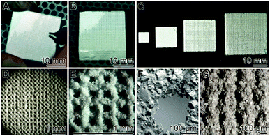 | ||
| Fig. 1 3D printing of grid layers, prepared from regular blocks. Computer-guided printing of layered grids was performed as described under “Material and Methods”. (A) An individual grid layer was peeled off from a block. (B) A regular block with a size of 27 × 27 × 12 mm3 was routinely used for the studies, described here. (C) Blocks of different sizes, fabricated from Ca-sulfate scaffold, are shown. The blocks that are composed of 25 individual grid layers had been fabricated by computer-guiding. (D) Light microscopic image of an individual grid layer. (E and F) Higher magnification of the layers; SEM. (G) A grid layer prior to a final cleaning through air blowing. | ||
Microscopic images
The grid layers were inspected both light microscopically with a VHX-600 Digital Microscope or a VK-8710 3D Laser Microscope from KEYENCE (Neu-Isenburg, Germany) and by scanning electron microscopy (SEM). The SEM images were taken with a LEO 1530 high resolution field emission scanning electron microscope (Zeiss/LEO, Oberkochen; Germany).Energy dispersive X-ray spectroscopy (EDX)
EDX analysis was performed with a FEI TECNAI F30 and a Nova 600 NanoLab SEM/FIB, equipped with an EDAX Division EDX analyzer as described.11 Five parallel analyses were performed per sample; a representative spectrum for each of the materials is given under “Results”.Cells and incubation conditions
The human osteogenic sarcoma cells, SaOS-232 were passaged in McCoy's medium, supplemented with 5% heat-inactivated FCS [fetal calf serum], 2 mM L-glutamine, and gentamicin (50 μg ml−1) in 25 cm2 flasks in a humidified incubator at 37 °C and 5% CO2, as described.9The experiments to test the influence of the grid layers were performed in 24-multi-well plates (Orange Scientifique, Braine-l'Alleud; Belgium) and cultured in McCoy's medium (as above). Into the wells (diameter of 14.5 mm) approximately 10 × 10 mm sized grid layers are inserted and then 2 ml medium were added. Where indicated the assays were supplemented with mineralization activation cocktail, composed of 5 mM β-glycerophosphate [β-GP], 50 mM ascorbic acid [AA] and 10 nM dexamethasone [DEX].9,33 SaOS-2 cells (1 × 10⁵ cells ml−1) were seeded onto each grid. Then the cells were cultivated for 4 d in McCoy's medium/5% FCS; if activated for hydroxyapatite formation the culture medium was replaced by McCoy's medium/5% FCS, supplemented with the mineralization cocktail and incubation was continued for 5 d.
Hydroxyapatite formation (“OsteoImage Mineralization Assay”)
Staining for hydroxyapatite production of SaOS-2 cells was performed by application of the “OsteoImage Mineralization Assay”, following the protocol supplied by the manufacturer and following the application procedure described.34 The “OsteoImage Assay” semi-quantitatively visualizes in vitro mineralization by osteogenic cells, like SaOS-2 cells in the present study. The dye binds to the hydroxyapatite nodules and deposits onto the cells. In parallel the samples were treated with DRAQ5 (Biostatus, Shepshed; UK). Finally, the samples were inspected with a confocal microscope (LSM 710) Zeiss (Oberkochen; Germany). The fluorescence of the OsteoImage reagent was detected with the laser applying the following characteristics of excitation/emission wavelength at 492 nm/520 nm and the fluorescence for the blue-stained nuclei (DRAQ5) at an excitation/emission wavelength of 650 nm/680 nm.Quantitative real-time RT-PCR (qRT-PCR) analysis
SaOS-2 cells suspended in 24-multi-well plates, were grown for 4 d in McCoy's medium/5% FCS, and were then transferred into McCoy's medium/5% FCS, supplemented with mineralization cocktail. The assays were continually grown for 1 d or 5 d, as described.9 After termination of the incubation the cells were harvested by gentle mechanically shaking in PBS [phosphate buffered saline], supplemented with 10 μl ml−1 of TRIzol reagent and total RNA was extracted as described.35 Then, quantitative real-time PCR (qPCR) experiments were performed in an iCycler (Bio-Rad) and using the “Absolute Blue SYBR Green” master mixture (ABgene, Hamburg; Germany) as well as 5 pmol of the following primers: for the house keeping gene GAPDH (glyceraldehyde 3-phosphate dehydrogenase, GenBank accession number NM_002046.3) Fwd: 5′-ACTTTGTGAAGCTCATTTCCTGGTA-3′ [nt1019 to nt1043] and Rev: 5′-TTGCTGGGGCTGGTGGTCCA-3′ [nt1117 to nt1136] (product size 118 bp); RANKL (AF019047) Fwd: 5′-AGAGCGCAGATGGATCCTAA-3′ [nt339 to nt358] and Rev: 5′-TTCCTTTTGCACAGCTCCTT-3′ [nt499 to nt518] (180 bp), and OPG (U94332.1) Fwd: 5′-GCAGCGGCACATTGGAC-3′ [nt937 to nt953] and Rev: 5′-CCCGGTAAGCTTTCCATCAA-3′ [nt986 to nt1005] (69 bp). In a second series of experiments the expression level of BMP-2 was determined by applying the primers (NM_001200.2):8 Fwd: 5′-ACCCTTTGTACGTGGACTTC-3′ [nt1681 to nt1700] and Rev: 5′-GTGGAGTTCAGATGATCAGC-3′ [nt1785 to nt1804, 124 bp]. The threshold position had been set to 50.0 RFU [relative fluorescence units] above PCR subtracted baseline for all runs. Further reaction conditions had been given previously.9 The mean Ct values and efficiencies were calculated by the iCycler software (Bio-Rad, Hercules, CA; USA). The estimated PCR efficiencies were in a range of 95–103%. Expression levels of the respective transcripts (RANKL, OPG and BMP-2) were correlated to the reference gene GAPDH to determine relative expression [e.g. EGAPDHCtGAPDH/ERANKLCtRANKL] where “E” describes PCR efficiency and “Ct” represents the threshold cycle.36Element analysis
The element analysis was performed by applying atomic absorption spectrometry combined with spectrophotometric and titrimetric procedures, as described.37,38Statistical analysis
The results were statistically evaluated using the paired Student's t-test.39Results
3D printing of grid layers
Regular blocks were 3D printed as described under “Material and Methods”. Routinely the 27 × 27 × 12 mm3 blocks, composed of the layered grids, were prepared (Fig. 1B). They were built of 25 layers having a grid size of 200 μm each (Fig. 1D–F). Individual layers were ablated with a scalpel from the blocks (Fig. 1A) and then used for the cell culture experiments. With the technique applied block sizes larger than 27 × 27 × 12 mm3 can also be readily fabricated; likewise also smaller blocks can be printed (Fig. 1C). The regular arrangement of the grid sizes (mesh size of 200 μm) can be documented both by light microscopy (Fig. 1D) and by SEM analysis (Fig. 1E and F). The pore size of the non-cleaned layered grid is smaller (<120 μm) (Fig. 1G) and the pores reach their final size of 200 μm (Fig. 1F) after thorough air blowing.Grid layers: chemical analyses
The individual grid layers, fabricated of Ca-sulfate, were processed with Ca-phosphate or silica, as described under “Material and Methods”. From those grid layers chemical analysis had was performed.EDX SPECTROSCOPIC DETERMINATION: parallel to the SEM analyses also EDX spectroscopic determination was performed (Fig. 2). The results show that the non-processed Ca-sulfate layered grids show distinct signals for O, Mg, S, and Ca, and a small peak for C. The Mg signals originate from Mg-sulfate that had been used for hardening/impregnation of the samples (Fig. 2A). The grid layers processed/impregnated with Ca-phosphate give large spectroscopic signals for O, Mg (small), P and Ca (Fig. 2B). Finally, the representative spectrum from a silica processed Ca-sulfate grid layer highlights, as expected, signals for O, Mg, Si, S, and Ca (Fig. 2C).
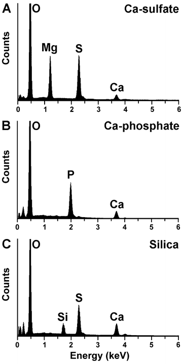 | ||
| Fig. 2 Element distribution within the 3D printed grid layers. Representative spectra from the following layers are shown: (A) non-processed Mg-sulfate grid, (B) grid processed with Ca-phosphate and (C) grid layer after treatment with silica. Signals reflecting the elements carbon (C), oxygen (O), magnesium (Mg), phosphorus (P), sulfur (S) and calcium (Ca) are marked. | ||
ELEMENT ANALYSIS: the element composition of the grids was determined by routine chemical analysis procedures, as mentioned under “Material and Methods”. The data are summarized in Table 1, and reflect that the dominant elements in the Ca-sulfate grids are Ca, S and O.
| Scaffold | Ca w/w (%) | S w/w (%) | O w/w (%) | P w/w (%) | Si w/w (%) |
|---|---|---|---|---|---|
| Ca-sulfate | 27.8 | 22.5 | 44.8 | — | — |
| Ca-phosphate impregnated Ca-sulfate | 28.7 | 16.9 | 42.3 | 4.2 | — |
| Silica impregnated Ca-sulfate | 23.2 | 18.7 | 45.3 | — | 7.0 |
Growth of SaOS-2 cells onto the scaffold
SaOS-2 cells were seeded to the 24-multi-well plates, into which the grid layers were inserted, and cultivated in McCoy's medium/5% FCS for 4 d. Then the cells were removed and the grid layers inspected by SEM (Fig. 3). The solid grids, both the non-processed Ca-sulfate, and the Ca-phosphate or silica processed grid layers, retain their overall structural integrity (Fig. 3A and D; Fig. 3B and E; Fig. 3C and F). The individual Paris powder grains from the Ca-phosphate (Fig. 3E) and silica grid layers (Fig. 3F) show a 50% smaller size than those composing the Ca-sulfate layers (Fig. 3D).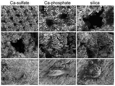 | ||
| Fig. 3 Cultivation of SaOS-2 cells onto non-processed Ca-sulfate grids (A, D and G), on Ca-phosphate grids (B, E and H) or on silica-processed grid layers (C, F and I); SEM. Where present, SaOS-2 cells are marked (c). | ||
An extensive screening for cells, after incubation for 4 d on the grid layers by the SEM technique revealed that the Ca-sulfate grids are colonized with a lower number of SaOS-2 cells (Fig. 3G), compared to the grids processed with Ca-phosphate (Fig. 3H) or silica (Fig. 3I).
Mineralization of SaOS-2 cells onto the scaffold
A semi-quantitative assessment of the SaOS-2 cell density after incubation of the cells in McCoy's medium/5% for 4 d, followed by a subsequent incubation for 5 d in this medium, supplemented with mineralization cocktail, was achieved by application of the specific hydroxyapatite detecting [using the OsteoImage dye] staining system and of the nuclei staining dye DRAQ5. After the 4 d/5 d incubation period the grids were removed from the 24-multi-well plates, washed and subjected to the dye staining procedure. The samples were analyzed by confocal laser scanning microscopy under fluorescence light wavelengths, specific for the OsteoImage dye and for DRAQ5. The images in Fig. 4 show that the cell densities, as assessed by DRAQ5 staining (Fig. 4A, Fig. 4C and Fig. 4E), are – if at all – only marginally different in the three assay systems (Ca-sulfate, Ca-phosphate, and silica). However, if the intensities obtained after the OsteoImage fluorescence staining are compared it becomes obvious that the OsteoImage intensity in the assays of SaOS-2 cells, grown on Ca-sulfate, is significantly lower (Fig. 4B), if compared to the intensities recorded in samples, grown onto Ca-phosphate grids (Fig. 4D). The highest staining intensities are seen after inspection of the cells, grown and activated (mineralization cocktail) onto silica grids (Fig. 4F).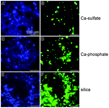 | ||
Fig. 4 Fluorescent staining of SaOS-2 cells with DRAQ5, for identification of the blue stained cell nuclei (A, C and E), or with the green fluorescent dye (by OsteoImage) to stain specifically hydroxyapatite nodules on the cell surfaces of the SaOS-2 cells (B, D and F). As indicated, the cells were grown onto Ca-sulfate (![[A with combining low line]](https://www.rsc.org/images/entities/char_0041_0332.gif) and and ![[B with combining low line]](https://www.rsc.org/images/entities/char_0042_0332.gif) ), Ca-phosphate ( ), Ca-phosphate (![[C with combining low line]](https://www.rsc.org/images/entities/char_0043_0332.gif) and and ![[D with combining low line]](https://www.rsc.org/images/entities/char_0044_0332.gif) ) and silica ( ) and silica (![[E with combining low line]](https://www.rsc.org/images/entities/char_0045_0332.gif) and and ![[F with combining low line]](https://www.rsc.org/images/entities/char_0046_0332.gif) ) grids for 4 d in McCoy's medium/5% FCS and then for 5 d in McCoy's medium/5% FCS, supplemented with mineralization cocktail. After termination of the experiments the specimens were inspected with blue fluorescent light for DRAQ5 and green fluorescence for the OsteoImage dye. All scale bars measure 100 μm. ) grids for 4 d in McCoy's medium/5% FCS and then for 5 d in McCoy's medium/5% FCS, supplemented with mineralization cocktail. After termination of the experiments the specimens were inspected with blue fluorescent light for DRAQ5 and green fluorescence for the OsteoImage dye. All scale bars measure 100 μm. | ||
Differential regulation of OPG and RANKL transcription in SaOS-2 growing on the silica scaffold
In order to substantiate the semi-quantitative results on the increased synthesis of hydroxyapatite in SaOS-2 cells, growing onto silica-impregnated grids, a quantitative series of determinations on the expression levels of key mediators of biomineralization have been performed by qRT-PCR.SaOS-2 cells were cultivated onto silica impregnated grids for 4 d. Then the medium was changed and replaced by McCoy's medium/5% FCS, supplemented with mineralization cocktail. Incubation was processed for 1 or 5 d. After RNA extraction from the SaOS-2 cells the expression levels of OPG and RANKL were determined by qRT-PCR. Transcription of the housekeeping gene GAPDH was used as reference. The data show (Fig. 5) that the transcript level of RANKL does not significantly change from day 1 to day 5. However, the expression of OPG (correlated to the level of GAPDH) increases significantly from 8.9-fold with respect to the GAPDH steady-state level (day 1 after addition of the mineralization cocktail) to 31-fold at day 5. In turn, the expression ratio between OPG and RANKL increases as well from 1.6-fold (day 1) to 4.7-fold (day 5).
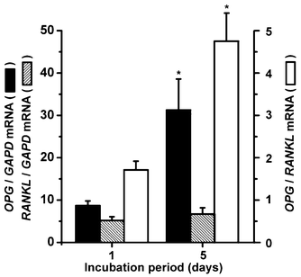 | ||
| Fig. 5 Biosilica regulated transcription of OPG and RANKL in SaOS-2 cells. RNA was extracted from cells that had been cultivated in McCoy's medium/FCS with mineralization cocktail for 1 or 5 d onto the silica grids. Then, the qRT-PCR technique was applied to determine the expression levels of OPG, RANKL, and the housekeeping gene GAPDH. The GAPDH expression level was chosen to normalize the transcript levels for OPG and RANKL. Closed bars, ratio of OPG/GAPDH expression; hatched bars, ratio of RANKL/GAPDH expression; open bars, ratio of the normalized OPG/RANKL transcript expression levels. Standard errors of the means (SEM) are indicated (n = five experiments per time point); *P < 0.05. | ||
Induction of BMP-2 transcription in SaOS-2 cells growing onto silica scaffold
SaOS-2 cells were incubated in mineralization medium (McCoy's medium/FCS with mineralization cocktail) for 1 to 7 d onto Ca-phosphate or on silica impregnated Ca-sulfate scaffold. Then, the cells were collected, the RNA extracted and finally qRT-PCR was performed. The data show that the steady-state transcript level of BMP-2 does not significantly change in SaOS-2 cells after incubation on Ca-phosphate impregnated scaffold. In contrast, if the cells were seeded onto silica-treated scaffold a significant increase of the transcript level is seen already after 3 d (from 0.13 [day 1] to 0.28 [day 3]). An extended incubation period further increased the BMP-2 level to 0.57 (day 5), or 0.41 (day 7) (Fig. 6).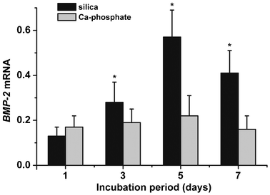 | ||
| Fig. 6 Expression transcript level of BMP-2 in SaOS-2 cells grown onto Ca-phosphate (grey) or silica impregnated Ca-sulfate (black) grids. The cells were harvested after the indicated period (1 d to 7 d) following their transfer to the McCoy's medium/FCS with mineralization cocktail. Then qRT-PCR was applied to determine the expression levels of BMP-2 and GAPDH. Standard errors of the means are shown (n = 5 experiments per time point). *P < 0.05 (correlated to the expression level at day 1). | ||
Discussion
In a number of clinical situations bone defects must be filled with a suitable material as they allow complicated fractures, explantation sites, or bone losses around protheses or extracted teeth.1 Since autogenic, allogenic, and xenogenic transplants are often not available or not indicated, semi- or fully synthetic bone substitution materials must be used instead. This material must be ideally characterized by a sufficient mechanical stability, should not elicit undesirable biological reactions and should be biodegradable in order to allow its fast replacement and in parallel an ingrowth of newly regenerating bone material. Bone substitution material, acting as a key scaffold component for tissue engineering during bone regeneration, should serve as a template for bone and connective tissue cells to adhere and should be biomimetic, in the sense that it acts not only osteoconductive, but also osteoinductive/osteogenic.40 Depending on the size of the cavity and the strength of the surrounding bone material, the bone substitution material can be fabricated either as individual particles or as single blocks.41In previous articles we reported that silica/bio-silica, which has related polycondensation characteristics like inorganic polymeric silica,20,42 causes in a sol/gel consistence state an induction of BMP-2 gene expression8 and an upregulation of the mediator OPG both on the gene and protein level.9 These properties qualify this inorganic polymer as a potentially suitable material for the application as a bone substitution material also in vivo.9 Silica, if formed in vitro, is a soft material that can be hardened by physical treatments,43 or by addition of organic additives.44 In order to reach a sufficient mechanical stability of the potential bone substitution scaffold we used in the present study computer-designed 3D printed free-standing blocks, formed of 25 grid layers, that had been printed in a layer-by-layer fabrication process from Ca-sulfate. Individual grid layers had been ablated and, after hardening with Mg-sulfate, directly transferred to the cell culture multi-well plates or after impregnation with Ca-phosphate or with silica. Those grids proved to be biocompatible. Accomplishing the aim of the present study to evaluate if the silica impregnated scaffold retains its property to act as a selective inducer of BMP-2 and OPG also in this fabrication form and state, the respective gene expression studies have been performed. The results revealed that SaOS-2 cells, attached and grown onto silica impregnated Ca-sulfate grids, significantly show an upregulated steady-state level of BMP-2 and OPG transcripts.
The present data surely can be considered as a further step to profile (bio)-silica as an alternative bone substitution material to the hitherto used organic/inorganic or purely inorganic scaffolds. The data gathered in the recently published8,9 and the current investigation here are supporting the assumption that (bio-)silica represents a scaffold that might act in an osteoinductive manner on SaOS-2 cells. As schematically outlined in Fig. 7 the silica impregnated scaffold provides, more superior than the Ca-phosphate impregnated grids, a material turning the SaOS-2 cells to a BMP-2 and OPG producing state. Future studies have to test also the potential ability of the cells, growing on this scaffold, to synthesize the osteoclast inhibitory factor, as recently shown for SaOS-2 cells exposed to silica in suspension.10
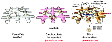 | ||
| Fig. 7 Schematic outline of the functionality of the Ca-sulfate, as well as the Ca-phosphate or silica impregnated scaffold on the expression level of BMP-2, OPG and the osteoclast inhibitory factor. The existing data suggest that both Ca-sulfate and Ca-phosphate impregnated Ca-sulfate scaffolds act only in a limited osteoinductive manner, while the silica impregnated scaffold inductively transform SaOS-2 cells to a state to produce elevated levels of BMP-2 and OPG. Studies on the potential of this scaffold to induce also the osteoclast inhibitory factor are in progress. | ||
Studies in the future will be focused on the 3D printing of solid silica scaffold by using a silica glass powder, perhaps enriched with Ca/F-phosphate,45 that becomes hardened during printing by using either the enzyme silicatein,44 or polyethylene glycol.46 The bio-silica scaffold, prepared enzymatically by silicatein20 but also like the silica scaffold, chemically synthesized by polycondensation, represents a moldable and – in the case of bio-silica – even self-repairing – healing material.20,47 Even more, bio-silica proved to be compatible to bacterial cells and allowed them to proliferate;48 likewise the same property had been described for purely inorganic silica obtained by sol–gel chemistry.49 The usefulness of silicatein for embedding bacterial cells has also been substantiated by the finding that this enzyme can catalyze the formation of layered amorphous titanium phosphates onto Escherichia coli cells.50 Therefore future efforts will be directed to evaluate to which degree (bio-)silica could be used for cell embedding into precisely designed scaffold material allowing a defect-matching design of bio-printed and bio-fabricated biomaterial. Efforts into this direction have been proposed already some time ago51 and are currently actively fostered ahead.52 First experiments performed by us show that SaOS-2 cells, growing in alginate hydrogel together with silica, synthesize already in the absence of added BMP-2 an increased quantity of hydroxyapatite.53
Acknowledgements
W.E.G. M. is a holder of an ERC Advanced Investigator Grant (no. 268476 BIOSILICA) as well as of an ERC proof-of-concept grant (no. 324564; Silica-based nanobiomedical approaches for treatment of bone diseases). This work was supported by grants from the European Commission (large-scale integrating project project no. 311848 – BlueGenics; project no. FP7-KBBE-2010-4-266033 – SPECIAL; project no. PIRSES-GA-2009-246987 – European-Chinese Research Staff Exchange Cluster MarBioTec*EU-CN*), the International Human Frontier Science Program, the German Bundesministerium für Bildung und Forschung – International Bureau (no. CHN 09/1AP – German-Chinese Joint Lab on Bio-Nano-Composites), the Public Welfare Project of Ministry of Land and Resources of the People's Republic of China (grant no. 201011005-06) and the International S & T Cooperation Program of China (grant no. 2008DFA00980).References
- M. Epple, Biomimetic bone substitution materials, in Biomineralisation: Medical and Clinical Aspects, ed. M. Epple and E. Baeuerlein, Weinheim:Wiley-VCH, 2007, 81–95 Search PubMed.
- M. E. Marquis, E. Lord, E. Bergeron, O. Drevelle, H. Park, F. Cabana, H. Senta and N. Faucheux, Front. Biosci., 2009, 14, 1023–1067 CrossRef CAS.
- J. M. Oliveira, M. T. Rodrigues, S. S. Silva, P. B. Malafaya, M. E. Gomes, C. A. Viegas, I. R. Dias, J. T. Azevedo, J. F. Mano and R. L. Reis, Biomaterials, 2006, 27, 6123–6137 CrossRef CAS.
- K. Ochi, G. Chen, T. Ushida, S. Gojo, K. Segawa, H. Tai, K. Ueno, H. Ohkawa, T. Mori, A. Yamaguchi, Y. Toyama, J. Hata and A. Umezawa, J. Cell. Physiol., 2003, 194, 45–53 CrossRef CAS.
- K. Zhang, Y. Ma and L. F. Francis, J. Biomed. Mater. Res., 2002, 61, 551–563 CrossRef CAS.
- X. H. Wang, H. C. Schröder, M. Wiens, H. Ushijima and W. E. G. Müller, Curr. Opin. Biotechnol., 2012, 23, 570–578 CrossRef CAS.
- S. S. Liao, F. Z. Cui, W. Zhang and Q. L. Feng, J. Biomed. Mater. Res., 2004, 69B, 158–165 CrossRef CAS.
- M. Wiens, X. H. Wang, U. Schloßmacher, I. Lieberwirth, G. Glasser, H. Ushijima, H. C. Schröder and W. E. G. Müller, Calcif. Tissue Int., 2010, 87, 513–524 CrossRef CAS.
- M. Wiens, X. H. Wang, H. C. Schröder, U. Kolb, U. Schloßmacher, H. Ushijima and W. E. G. Müller, Biomaterials, 2010, 31, 7716–7725 CrossRef CAS.
- H. C. Schröder, X. H. Wang, M. Wiens, B. Diehl-Seifert, K. Kropf, U. Schloßmacher and W. E. G. Müller, J. Cell. Biochem., 2012, 113, 3197–3206 CrossRef.
- W. E. G. Müller, X. H. Wang, B. Diehl-Seifert, K. Kropf, U. Schloßmacher, I. Lieberwirth, G. Glasser, M. Wiens and H. C. Schröder, Acta Biomater., 2011, 7, 2661–2671 CrossRef.
- X. H. Wang, H. C. Schröder, B. Diehl-Seifert, K. Kropf, U. Schloßmacher, M. Wiens and W. E. G. MüllerJ. Tissue Eng. Regen. Med., 2012 DOI:10.1002/term.1465.
- X. H. Wang, H. C. Schröder, M. Wiens, L. Gan, W. Tremel and W. E. G. Müller, From biosilica of sponges (Demospongiae and Hexactinellida) to fabricated biomedical materials, in Handbook of Marine Natural Products, ed. E. Fattorusso, O. Taglialatela-Scafati and W. H. Gerwick, Springer-Verlag Berlin Heidelberg, 2012, 1259–1284 Search PubMed.
- E. M. Carlisle, Silicon as an essential trace element in animal nutrition, in Silicon Biochemistry, ed. D. Evered and M. O'Connor, CIBA Foundation Symposium 121, Chichester, John Wiley & Sons Ltd, 1986, 123–136 Search PubMed.
- K. V. Dyck, H. Robberecht, R. V. Cauwenbergh, V. V. Vlaslaer and H. Deelstra, Biol. Trace Elem. Res., 2000, 77, 25–32 CrossRef.
- E. M. Carlisle, Science, 1972, 178, 619–621 CAS.
- R. Jugdaohsingh, J. Nutr. Health Aging, 2007, 11, 99–110 CAS.
- W. E. G. Müller, X. H. Wang, F. Z. Cui, K. P. Jochum, W. Tremel, J. Bill, H. C. Schröder, F. Natalio, U. Schloßmacher and M. Wiens, Appl. Microbiol. Biotechnol., 2009, 83, 397–413 CrossRef.
- D. E. Morse, Trends Biotechnol., 1999, 17, 230–232 CrossRef CAS.
- X. H. Wang, H. C. Schröder, K. Wang, J. A. Kaandorp and W. E. G. Müller, Soft Matter, 2012, 8, 9501–9518 RSC.
- H. J. Hausser and R. E. Brenner, Biochem. Biophys. Res. Commun., 2005, 333, 216–222 CrossRef CAS.
- H. Tanaka, E. Nagai, H. Murata, T. Tsubone, Y. Shirakura, T. Sugiyama, T. Taguchi and S. Kawai, Rheumatology, 2001, 40, 1163–1168 CrossRef CAS.
- W. S. Simonet, D. L. Lacey, C. R. Dunstan, M. Kelley, M. S. Chang, R. Lüthy, H. Q. Nguyen, S. Wooden, L. Bennett, T. Boone, G. Shimamoto, M. DeRose, R. Elliott, A. Colombero, H. L. Tan, G. Trail, J. Sullivan, E. Davy, N. Bucay, L. Renshaw-Gegg, T. M. Hughes, D. Hill, W. Pattison, P. Campbell, S. Sander, G. Van, J. Tarpley, P. Derby, R. Lee and W. J. Boyle, Cell, 1997, 89, 309–319 CrossRef CAS.
- T. Suda, N. Takahashi, N. Udagawa, E. Jimi, M. T. Gillespie and T. J. Martin, Endocr. Rev., 1999, 20, 345–357 CrossRef CAS.
- M. Wiens, X. H. Wang, F. Natalio, H. C. Schröder, U. Schloßmacher, S. Wang, M. Korzhev, W. Geurtsen and W. E. G. Müller, Adv. Eng. Mater., 2010, 12, B438–B450 CrossRef.
- M. Waselau, M. Patrikoski, B. Mannerström, M. Raki, K. Bergström, B. Rechenberg von and S. Miettinen, Journal of Stem Cell Research & Therapy, 2012, 2, 125 Search PubMed.
- H. Seitz, W. Rieder, S. Irsen, B. Leukers and C. Tille, J. Biomed. Mater. Res. B Appl. Biomater., 2005, 74, 782–788 CrossRef.
- W. S.Pietrzak and R. Ronk, J. Craniofacial Surg., 2000, 11, 327–333 CrossRef.
- J. Wiltfang, H. A. Merten, K. A. Schlegel, S. Schultze-Mosgau, F. R. Kloss, S. Rupprecht, P. Kessler and J. Biomed, J. Biomed. Mater. Res., 2002, 63, 115–121 CrossRef CAS.
- R. Lowmunkong, T. Sohmura, Y. Suzuki, S. Matsuya and K. Ishikawa, J. Biomed. Mater. Res. B Appl. Biomater., 2009, 90, 531–539 CrossRef.
- U. Schloßmacher, M. Wiens, H. C. Schröder, X. H. Wang, K. P. Jochum and W. E. G. Müller, FEBS J., 2011, 278, 1145–1155 CrossRef.
- J. Fogh, J. M. Fogh and T. Orfeo, J. Natl. Cancer Inst., 1977, 59, 221–226 CAS.
- S. L. Cheng, J. W. Yang, L. Rifas, S. F. Zhang and L. V. Avioli, Endocrinology, 1994, 134, 277–286 CrossRef CAS.
- F. Langenbach, K. Berr, C. Naujoks, A. Hassel, M. Hentschel, R. Depprich, N. R. Kubler, U. Meyer, H. P. Wiesmann, G. Kögler and J. Handschel, Nat. Protoc., 2011, 6, 1726–1735 CrossRef CAS.
- W. E. G. Müller, X. H. Wang, H. C. Schröder, M. Korzhev, V. A. Grebenjuk, J. S. Markl, K. P. Jochum, D. Pisignano and M. Wiens, FEBS J., 2010, 277, 1182–1201 CrossRef.
- M. W. Pfaffl, Nucleic Acids Res., 2001, 29, 2002–2007 CrossRef.
- L. Shapiro, Geol. Survey Bull., 1975, 1401, 1–76 Search PubMed.
- J. J. Swab and P. J. Huang, Technical report, 2001, ARL-TR-2436 Search PubMed.
- L. Sachs, Angewandte Statistik, Springer:Berlin, 1984, 242 Search PubMed.
- W. S. Khan, F. Rayan, B. S. Dhinsa and D. Marsh, Stem Cells International, 2012 DOI:10.1155/2012/236231.
- M. Klein, H. Goetz, S. Pazen, B. Al-Nawas, W. Wagner and H. Duschner, Clin. Oral Implants Res., 2009, 20, 67–74 CrossRef.
- D. J. Belton, O. Deschaume and C. C. Perry, FEBS J., 2012, 279, 1710–1720 CrossRef CAS.
- X. H. Wang, H. C. Schröder, D. Brandt, M. Wiens, I. Lieberwirth, G. Glasser, U. Schloßmacher, S. F. Wang and W. E. G. Müller, ChemBioChem, 2011, 12, 2316–2324 CrossRef CAS.
- H. C. Schröder, X. H. Wang, A. Manfrin, S. H. Yu, V. A. Grebenjuk, M. Korzhev, M. Wiens, U. Schloßmacher and W. E. G. Müller, J. Biol. Chem., 2012, 287, 22196–22205 CrossRef.
- M. Kobayashi, T. Nakamura, J. Tamura, H. Iida, H. Fujita, T. Kokubo and T. Kikutani, J. Biomed. Mater. Res., 1997, 37, 68–80 CrossRef CAS.
- L. H. Mei, D. Q. Lin, Z. Q. Zhu and Z. X. Han, J. Chem. Eng. Data, 1995, 40, 1168–1171 CrossRef CAS.
- W. E. G. Müller, U. Schloßmacher, X. H. Wang, A. Boreiko, D. Brandt, S. E. Wolf, W. Tremel and H. C. Schröder, FEBS J., 2008, 275, 362–370 CrossRef.
- W. E. G. Müller, S. Engel, X. H. Wang, S. E. Wolf, W. Tremel, N. L. Thakur, A. Krasko, M. Divekar and H. C. Schröder, Biomaterials, 2008, 29, 771–779 CrossRef.
- N. Nassif, O. Bouvet, M. N. Rager, C. Roux, T. Coradin and J. Livage, Nat. Mater., 2002, 1, 42–44 CrossRef CAS.
- P. Curnow, P. Bassette, D. Kisailus, M. M. Murr, P. S. Daugherty and D. E. Morse, J. Am. Chem. Soc., 2005, 127, 15749–15755 CrossRef CAS.
- V. Mironov, T. Boland, T. Trusk, G. Forgacs and R. R. Markwald, Trends Biotechnol., 2003, 21, 157–161 CrossRef CAS.
- S. Wüstemail, R. Müller and S. Hofmann, J. Funct. Biomater., 2011, 2, 119–154 CrossRef.
- W. E. G. Müller, H. C. Schröder, Q. L. Feng, U. Schloßmacher, T. Link and X. H. Wang, Development of a morphogenetically active scaffold for three-dimensional printing processes: biosilica/alginate hydrogel for SaOS-2 Cell cultivation, submitted Search PubMed.
| This journal is © The Royal Society of Chemistry 2013 |
