 Open Access Article
 This Open Access Article is licensed under a Creative Commons Attribution-Non Commercial 3.0 Unported Licence
A three step continuous flow synthesis of the biaryl unit of the HIV protease inhibitorAtazanavir
Luciana
Dalla-Vechia
a,
Benedikt
Reichart
b,
Toma
Glasnov
b,
Leandro S. M.
Miranda
a,
C. Oliver
Kappe
*bc and
Rodrigo O. M. A.
de Souza
*a
aBiocatalysis and Organic Synthesis Group, Chemistry Institute, Federal University of Rio de Janeiro, CEP 22941 909, Rio de Janeiro, Brazil. E-mail: rodrigosouza@iq.ufrj.br; Fax: (+55)-212-5627001
bChristian Doppler Laboratory for Microwave Chemistry (CDLMC) and Institute of Chemistry, Karl-Franzens-University Graz, Heinrichstrasse 28, A-8010 Graz, Austria. E-mail: oliver.kappe@uni-graz.at; Fax: (+43)-316-3809840; Tel: (+43)-316-3805352
cChemistry Department, Faculty of Science, King Abdulaziz University, P.O. Box 80203, Jeddah 21589, Saudi Arabia
First published on 14th August 2013
Abstract
The development of multistep continuous flow reactions for the synthesis of important intermediates for the pharmaceutical industry is still a significant challenge. In the present contribution the biaryl-hydrazine unit of Atazanavir, an important HIV protease inhibitor, was prepared in a three-step continuous flow sequence in 74% overall yield. The synthesis involved Pd-catalyzed Suzuki–Miyaura cross-coupling, followed by hydrazone formation and a subsequent hydrogenation step, and additionally incorporates a liquid–liquid extraction step.
Introduction
Continuous flow technology has attracted the attention of the organic chemistry community in the last decade, both as an enabling tool to enhance organic synthesis and as a manufacturing method.1,2 In 2007, the ACS Green Chemistry Institute (GCI) ranked continuous flow processing as a high priority research area for pharmaceutical and fine chemical manufacturing.3 Since that time, significant progress has been made in establishing continuous flow methods for the production of important target compounds or valuable synthetic building blocks.4 Several reviews discuss in detail the benefits of applying continuous flow methods in organic synthesis, including better mixing, efficient mass and heat transfer and the ability to readily scale-up a given flow process by applying numbering-up or scaling-out principles.1,2 A particularly challenging area in flow chemistry is to perform multi-step reaction sequences where each synthetic step – if possible – should be directly linked to the following step without isolation or purification of the corresponding intermediates.5 The continuous flow synthesis of active pharmaceutical ingredients (APIs), which typically involves a significant number of synthetic steps, is therefore clearly a rather complex operation.6In this context we believe that a continuous flow synthesis of the protease inhibitorAtazanavir (1) is of significant interest. Atazanavir, approved by the U.S. Food and Drug Administration (FDA) in 2003, is an antiretroviral drug that is used to treat infection with human immunodeficiency virus (HIV).7 It is estimated that nearly 7.7 million people in Africa need treatment for HIV and do not have access to appropriate medication.8 Notably, Brazil is a pioneer in providing free medication to HIV patients and in 2007 the Brazilian government spent 850 million USD treating 200![[thin space (1/6-em)]](https://www.rsc.org/images/entities/char_2009.gif) 000 HIV patients.9Atazanavir is one of the most prescribed protease inhibitors in Brazil (and worldwide) and thus a sufficient and cost effective supply of Atazanavir is of prime importance.
000 HIV patients.9Atazanavir is one of the most prescribed protease inhibitors in Brazil (and worldwide) and thus a sufficient and cost effective supply of Atazanavir is of prime importance.
The general retrosynthetic analysis of the Atazanavir (1) molecule is shown in Fig. 1 and reveals an assembly of three different building blocks.10 The subject of the work described herein is the synthesis of the biaryl building block 310via a three step continuous flow protocol that avoids the isolation and (off-line) purification of any intermediates.
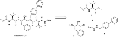 | ||
| Fig. 1 General retrosynthetic analysis for Atazanavir (1). | ||
Results and discussion
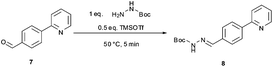
The synthetic route developed by Bristol–Meyers–Squibb (BMS) for the N-Boc hydrazine biaryl intermediate 3 is depicted in Scheme 1.10 These conditions were used as a reference point for an initial optimization of batch experiments utilizing controlled microwave heating, which were then translated to continuous flow conditions.11 The synthetic steps consist of a Suzuki–Miyaura coupling of 4-formyl-phenylboronic acid (5) and 2-bromo pyridine (6), leading to the formation of biaryl moiety 7, which is then reacted with Boc-hydrazine (tert-butyl carbazate) to furnish hydrazone8. After transfer hydrogenation, the target intermediate 3 can be obtained in 53% overall yield.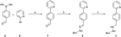 | ||
| Scheme 1 Synthetic route developed by Bristol–Meyers–Squibb (BMS) for the N-Boc hydrazine biaryl intermediate 3. Reagents and conditions: (a) 1.9 equiv. 5, 0.2 mol% Pd(PPh3)4, aqueous 3 M Na2CO3, toluene–ethanol (4:3), reflux 20 h, 80% yield. (b) N-Boc hydrazine (1 equiv.), toluene–2-propanol (4:3), reflux 2 h and then 22 °C for 16 h, 85% yield. (c) 1 mol% Pd/C (10%), HCO2Na (0.8 equiv.), ethanol–water (5.5:1), 57 °C for 1.5 h, 78% yield (overall yield 53%). | ||
We envisaged that the biphasic conditions proposed for the Suzuki–Miyaura cross coupling reaction (Scheme 1) could be a good starting point for our investigations since the desired biaryl product 7 could potentially be separated from the reaction mixture by simple phase separation, without involving complicated purification steps. The Suzuki–Miyaura cross-coupling employing 0.2 mol% Pd(PPh3)4 was therefore performed under sealed vessel microwave heating using essentially the BMS conditions described in Scheme 1. By applying 150 °C for 20 min, the conversion to product was higher than 99% as indicated in Table 1 (entry 1). Despite showing high conversion, this procedure was not considered economical owing to the large excess (1.9 equiv.) of boronic acid5 used. In our hands, attempts to reduce the amount of boronic acid were unsuccessful, leading to reduced conversion and/or selectivity.
|
|
||||||
|---|---|---|---|---|---|---|
| Entry | Boronic acid (equiv.) | Pd(PPh3)4 (mol%) | Base/additive | Solvent | Conversionb (%) | |
| Product | Side products | |||||
| a Reagents and conditions: organic phase: 2-bromo-pyridine 6 (0.23 mmol, 1 equiv.), 4-formyl-phenylboronic acid5, and Pd(PPh3)4 as a catalyst in 2.3 mL of organic solvent. Aqueous phase: a solution of the base in the indicated concentration (350 μL). Microwave heating was performed at 150 °C for 20 min. b HPLC peak area integration at 254 nm. | ||||||
| 1 | 1.9 | 0.2 | Na2CO3 (3.3 M) |
Toluene–EtOH (4:3) |
99.2 | 0.8 |
| 2 | 1.0 | 0.3 | K3PO4 (3.3 M) TBAB (10 mol%) |
Toluene–EtOH (4:3) |
94.2 | 2.5 |
| 3 | 1.0 | 0.3 | K3PO4 (3.3 M) |
Toluene–EtOH (4:3) |
96.5 | 2.3 |
| 4 | 1.2 | 0.3 | K3PO4 (3.3 M) |
Toluene–EtOH (4:3) |
96.7 | 2.1 |
| 5 | 1.2 | 0.3 | K3PO4 (1.6 M) |
Toluene–EtOH (4:3) |
97.2 | 2.5 |
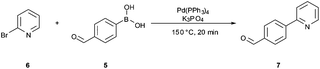
In a recent publication, Buchwald and co-workers have reported a very efficient biphasic continuous flow carbon–nitrogen coupling protocol where the addition of tribasic potassium phosphate and tetrabutylammonium bromide (TBAB) to the aqueous phase enhanced the conversion to the biaryl product.12 Evaluating these coupling conditions for the Suzuki–Miyaura batch coupling reaction described herein provided 94% conversion to the desired biaryl product 7 using only 1 equiv. of the boronic acid and 0.3 mol% of the Pd catalyst (Table 1, entry 2). Cross-coupling without the addition of TBAB also resulted in good conversion and high selectivity to the desired biaryl product 7, demonstrating that no phase-transfer catalyst (PTC) is required under the high-temperature microwave conditions (Table 1, entry 3). Increasing the boronic acid concentration to 1.2 equiv. and reducing the amount of base slightly increased the product conversion (Table 1, entries 4 and 5). The desired biaryl derivative 7 was isolated in 91% yield from the latter experiment.
The microwave batch conditions were then translated to a continuous flow protocol11 utilizing an ASIA microreactor employing a two-feed (or a three-feed in the case of hydrazone formation) set-up with preheated 4 mL stainless steel coils (additional 325 μl preheating zone volume and 2175 μl cooling zone volume) with an inner diameter of 0.02 inch (∼0.5 mm). After some experimentation and minor modifications to reagent stoichiometry, a 95% conversion at 150 °C and 20 min residence time was achieved (Scheme 2). It is important to note that using a fixed bed reactor filled with 60–125 μm stainless steel beads of identical geometry as described by Buchwald12 did not improve the conversion or selectivity in this reaction compared to the coil reactor (data not shown). The conversion could also not be improved by increasing reaction temperature or residence time.
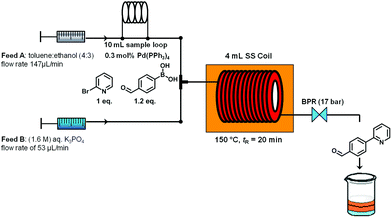 | ||
| Scheme 2 Suzuki–Miyaura cross coupling under continuous flow conditions. | ||
We subsequently evaluated the hydrazone formation 7 → 8 (Scheme 1) under microwave conditions, using the crude reaction mixture containing biaryl7 obtained after a simple phase separation (organic phase, toluene–ethanol) from the microwave-assisted biphasic Suzuki–Miyaura cross-coupling described above. The hydrazone formation was initially tested using ∼1.0 equiv. tert-butyl carbazate without the addition of acid as described in the BMS procedure,10 but in our hands it proved to be rather unreactive under these conditions (after 25 min of reaction at 120 °C the conversion was only 10%, Table 2, entry 5). Addition of various acids to the reaction mixture in most instances significantly increased the rate of hydrazone formation (Table 2, entries 1–4). However, in most cases the formation of the hydrazone was accompanied by salt precipitation and therefore was considered unsuitable for continuous flow processing. In order to avoid the formation of a precipitate, 0.5 equiv. of trimethylsilyltriflate (TMSOTf) was used as a Lewis acid. Gratifyingly, under these conditions excellent conversion (98%) to the corresponding hydrazone8 was obtained after 5 min at 50 °C without the formation of any precipitate (Table 3, entry 4).
|
|
|||
|---|---|---|---|
| Entry | Acid | Conditions | Conversionb (%) |
| a Reagents and conditions: crude organic phase from the Suzuki–Miyaura reaction (∼2.3 mL, theoretical concentration of 0.1 M, see Table 1, entry 5), t-butyl carbazate (0.23 mmol, 1 equiv.) and 5 equiv. acid concentration unless otherwise stated. b Conversion to product, HPLC peak area integration at 254 nm. | |||
| 1 | HCl | 50 °C/5 min | 98 |
| 2 | AcOH | 50 °C/5 min | 78 |
| 3 | CF3SO3H (0.5 eq.) | 50 °C/5 min | 97 |
| 4 | TMSOTf (0.5 eq.) | 50 °C/5 min | 98 |
| 5 | No acid | 120 °C/25 min | 10 |
|
|
|||||
|---|---|---|---|---|---|
| Entry | Feed A | Feed B | Feed C | t R | Conversionb (%) |
| a Flow reactions were performed in a Syrris Asia system by applying reagent loop technology, T-mixers and a reaction coil made from stainless steel. For further details, see the Experimental section. b Conversion to product. HPLC peak area integration at 254 nm. | |||||
| 1 | 0.1 M crude 7 | 0.05 M TMSOTf | — | 5 | 87.8 |
| 0.1 M carbazate | 0.5 equiv. | ||||
| 400 μL min−1 | 400 μL min−1 | ||||
| 2 | 0.1 M crude 7 | 0.075 M TMSOTf | — | 5 | 100 |
| 0.1 M carbazate | 0.75 equiv. | ||||
| 400 μL min−1 | 400 μL min−1 | ||||
| 3 | 0.075 M TMSOTf | 0.2 M carbazate | 5 | 80.5 | |
| 0.1 M crude 7 | |||||
| 0.75 equiv. | 1.0 equiv. | ||||
| 320 μL min−1 | |||||
| 320 μL min−1 | 160 μL min−1 | ||||
| 4 | 0.075 M TMSOTf | 0.24 M carbazate | 5 | 97.4 | |
| 0.1 M crude 7 | |||||
| 0.75 equiv. | 1.2 equiv. | ||||
| 320 μL min−1 | |||||
| 320 μL min−1 | 160 μL min−1 | ||||
| 5 | 0.075 M TMSOTf | 0.24 M carbazate | |||
| 0.1 M crude 7 | 8 | 99.0 | |||
| 0.75 equiv. | 1.2 equiv. | ||||
| 200 μL min−1 | |||||
| 200 μL min−1 | 100 μL min−1 | ||||
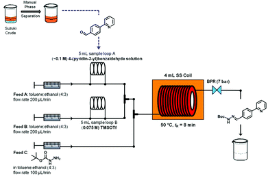
Again, the reaction conditions optimized under microwave heating were then translated to a continuous flow protocol. To the crude reaction mixture obtained from the continuous flow Suzuki–Miyaura protocol (organic phase,13 theoretical concentration of 0.1 M biaryl 7), 1.0 equiv. of tert-butyl carbazate was manually added to evaluate the optimum concentration of TMSOTf that would allow efficient hydrazone formation. Performing a two feed continuous flow hydrazone formation at 50 °C and a residence time of 5 min with 0.5 equiv. and 0.75 equiv. of TMSOTf (feed B) led to conversions of 87% and 100%, respectively (Table 3, entries 1 and 2). In order to develop a fully continuous two-step synthesis a three feed concept was developed in which the stream from the continuous flow Suzuki–Miyaura coupling (after phase separation, toluene layer,13 see Scheme 2) was initially mixed with a 0.075 M solution of TMSOTf in toluene–ethanol (4:3). tert-Butyl carbazate (0.2 M in toluene–ethanol (4:3)) was then added via a third pump before the reaction mixture was flowed through a stainless steel coil heated to 50 °C. Fine-tuning residence times and reagent stoichiometries using this approach ultimately allowed achieving high overall conversion and selectivity for hydrazone formation (Table 3, entries 3–5).
Finally, hydrazonehydrogenation was performed directly under continuous flow conditions using an H-Cube Pro reactor and a Pd/C catalyst cartridge.14 For optimization purposes pure hydrazone8 dissolved in a 4:3 mixture of toluene and ethanol (0.1 M) was processed through the reactor at a flow rate of 1 mL min−1 and atmospheric hydrogen pressure. Full conversion was achieved for hydrogenations carried out at 40 °C (Table 4, entry 4). When using the acidic crude hydrazone mixture (see above), prior neutralization of the acid was required since the acidic medium apparently poisons the Pd catalyst or otherwise inhibits the reduction process. Both triethylamine and K2CO3 were successfully tested as bases (Table 4, entries 5 and 6). Since a 0.5 M aqueous solution of K2CO3 provided better results (i.e., less side products), this was the preferred base for all further studies. Neutralization of the crude reaction mixture was first performed off-line in batch mode to demonstrate proof-of-principle. In the overall continuous flow process this extraction was performed in-line using a membrane-based liquid/liquid flow extraction module (FLLEX,15 see the Experimental section for details).
:3 mixture of toluene and ethanola
|
|
||||
|---|---|---|---|---|
| Entry | Temp (°C) | Hydrazine 3b (%) | Side productsb (%) | Remaining hydrazone8b (%) |
| a Experiments were performed in an H-Cube Pro flow reactor with the following conditions: flow rate 1 mL min−1, 10% Pd/C cartridge and atmospheric pressure of H2. For further details see the Experimental section. b HPLC peak area integration at 254 nm. | ||||
| Pure hydrazone in toluene–ethanol (0.1 M) | ||||
| 1 | 10 | 78.2 | 0 | 21.8 |
| 2 | 20 | 99.5 | 0 | 0.5 |
| 3 | 30 | 99.6 | 0 | 0.4 |
| 4 | 40 | 100 | 0 | 0 |
| Crude hydrazone after neutralization with TEA | ||||
| 5 | 40 | 85.0 | 15.0 | 0 |
| Crude hydrazone after washing with 0.5 M K2CO3 (FLLEX) | ||||
| 6 | 40 | 94.6 | 5.4 | 0 |
The neutralization of the reaction mixture with TEA leads to the formation of large amounts of a side product (Table 4, entry 5). In order to overcome the formation of this side product we decided to make a phase extraction of the acid using a basic solution of potassium carbonate (0.5 M). Gratifyingly, after washing with aqueous base the formation of this side-product was minimized and a good conversion was achieved. Manual washing with aqueous phase was then replaced by extraction on a flow liquid–liquid extractor (FLLEX),15 leading to high conversions without side products (Table 4, entry 6).
An overview of the three-step continuous flow process is depicted in Fig. 2. The Suzuki–Miyaura reaction takes place by pumping an organic mixture (toluene–ethanol 4:3) containing the boronic acid5, 2-bromo-pyridine (6) and the palladiumcatalyst through one pump, and an aqueous tribasic potassium phosphate solution through a second pump. In the first 4 mL stainless steel coil the reaction mixture is heated to 150 °C with a residence time of 20 min and the product stream collected. Phase separation of the triphasic product stream provides a biphasic toluene–ethanol mixture, containing biaryl intermediate 7 which is injected through a third pump to a second coil. Simultaneously, solutions of TMSOTf and tert-butyl-carbazate in toluene–ethanol (4:3) are pumped into the coil using two separate pumps. Hydrazone (8) formation takes place in this second coil at 50 °C and a residence time of 8 min. The outgoing stream is then pumped through a continuous flow liquid/liquid extractor (FLLEX)15 together with an aqueous potassium carbonate solution to eliminate the acid from the previous step. After the extraction, crude hydrazone8 is pumped through a flow hydrogenation unit applying a 10% Pd/C cartridge to provide the final biaryl product 3 in 74% overall yield after chromatographic purification.
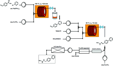 | ||
| Fig. 2 Overview of the three-step continuous flow synthesis of biaryl hydrazine intermediate of Atazanavir (3). | ||
Conclusion
In conclusion, in the present contribution we have developed a multistep synthesis of biaryl N-Boc-hydrazine 3 under continuous-flow conditions. The overall yield in this continuous process is 74%, which compares very favorably to the 53% overall batch yield originally described in the literature. In addition to the increased overall yield and the environmental and safety advantages inherent to the continuous process, our method does not require any off-line purification of intermediates and uses only phase extraction which can be readily automated. The fully continuous flow synthesis of the key intermediate 2 in the Atazanavir synthesis is currently under evaluation in our laboratories.Experimental section
General
1H-NMR spectra were recorded using a Bruker 300 MHz instrument. Chemical shifts (d) are expressed in ppm downfield from TMS as an internal standard. The letters s, bs, d, t, q, and m are used to indicate singlet, broad singlet, doublet, triplet, quadruplet, and multiplet, respectively. Analytical HPLC (Shimadzu LC20) analysis was carried out on a C18 reversed-phase (RP) analytical column (150 × 4.6 mm, particle size 5 μm) at 37 °C using a mobile phase A (water–acetonitrile 90:10 (v/v) + 0.1% TFA) and B (MeCN + 0.1% TFA) at a flow rate of 1.5 mL min−1. The following gradient was applied: a linear increase from solution 10% B to 100% B in 8 min, and hold at 100% solution B for 2 min. All solvents and chemicals were obtained from standard commercial vendors and were used without any further purification. All compounds studied in this work are known in the literature. The identification of products and intermediates was done by comparison with the literature spectrum data.
Microwave experiments
Microwave irradiation experiments were carried out using a Monowave 300 single-mode microwave reactor from Anton Paar GmbH (Graz, Austria). The experiments were performed in a 10 mL Pyrex microwave process vial equipped with a magnetic stirring bar at a rate of 600 rpm. Reaction times refer to hold times at the temperatures indicated and not to total irradiation times. The reaction conversions were evaluated by HPLC analysis at 254 nm.General procedure for Suzuki–Miyaura cross-coupling under microwave conditions (Table 1)
In a microwave process vial were placed: the organic reaction mixture containing 0.23 mmol (36.3 mg) of 2-bromo-pyridine, 0.28 mmol (42.0 mg) of 4-formyl-phenylboronic acid (1.2 equiv.) and 0.2 or 0.3 mol% of Pd(PPh3)4 in 2.3 mL of a mixture of toluene and ethanol (4:3); and the aqueous base, 1.6 M K3PO4 (350 μL). The vials were sealed with PEEK snap caps and standard polytetrafluoroethylene (PTFE)-coated silicone septa and the samples were irradiated for 20 minutes (fixed hold time) at 150 °C (∼9 bar). After the reaction time elapsed, the mixtures were cooled to 55 °C using compressed air.
Purification: the biphasic reaction mixture was separated and the organic layer was evaporated and subjected to silica gel column chromatography using a mixture of petroleum ether, ethyl acetate and triethylamine as an eluent (1:2:0.03). Yield under optimized conditions: 38.5 mg of 7 (91%).
General procedure for the synthesis of hydrazone 8 under microwave conditions (Table 2)
The biphasic mixture resulting from the Suzuki–Miyaura reaction (see above) was separated and to the organic solution (theoretical concentration of 0.1 M of Suzuki–Miyaura product 7) was added tert-butyl carbazate (0.23 mmol, 30.4 mg, 1 equiv.) and TMSOTf (0.12 mmol, 26.7 mg, 0.5 equiv.) in a microwave vial. The vials were sealed with PEEK snap caps and standard polytetrafluoroethylene (PTFE)-coated silicone septa and the samples were heated for 5 min (fixed hold time) at 50 °C. After the reaction time elapsed, the mixtures were cooled to 45 °C using compressed air.
Purification: the reaction mixture was neutralized with triethylamine and the solvent was evaporated. The crude residue was subjected to silica gel column chromatography using a mixture of petroleum ether, ethyl acetate and triethylamine as an eluent (1:2:0.03). Yield of 8 under optimized conditions: 61.5 mg (90%).
The reduction of the hydrazone to the corresponding hydrazine was directly tested in the H-Cube Pro flow reactor (ThalesNano Inc., Budapest, Hungary).
Flow experiments
The Suzuki–Miyaura reaction and hydrazone formation were performed in an ASIA 110 series microreactor (Syrris Ltd, Royston, UK), employing a two-feed (or three-feed in the case of hydrazone formation) microreactor stainless steel coil (4000 μl reaction volume, 325 μl preheating zone volume, 2175 μl cooling zone volume). The hydrogenation of the hydrazone was performed in the H-Cube Pro continuous flow reactor. The reaction conversions were evaluated by HPLC analysis at 254 nm.General procedure for Suzuki–Miyaura coupling in flow (Scheme 2)
Ten milliliters of the organic mixture containing 2-bromo-pyridine, 4-formyl-phenyl-boronic acid and catalytic Pd(PPh3)4 dissolved in toluene–ethanol (4:3) were loaded into the 10 mL PTFE loop module. By pumping the organic solventtoluene–ethanol 4:3 (flow rate feed A: 147 μl min−1) into the loop the organic mixture containing the starting materials was driven into the microreactor, while feed B (aqueous 1.6 M K3PO4, flow rate 53 μL min−1) was directly pumped into the two-feed stainless steel coil reactor. The 4 mL stainless steel coil reactor was heated to 150 °C on the coil heater adapter, and the reaction mixture was pumped through the reactor (overall flow rate of 200 μl min−1) and left the reactor after ∼32.5 min (20 min of residence time) of reaction time by passing through a backpressure regulator (17 bar). The collection program was as follows: fraction 1 (pre-fraction, include collection time from 32 minutes after injection to 37 minutes) was discarded; fraction 2 (steady state fraction, collection time from 37 minutes to 77 minutes and the total volume of 8 mL); fraction 3 (post-fraction, collection time from 77 minutes to 92 minutes) was also discarded. Only fraction 2 was used for the next step to avoid the dilution of the pre- and post-fractions. The tri-phasic reaction mixture (toluene, ethanol and aqueous base) obtained was separated in order to eliminate the aqueous phase. The organic layers (toluene and ethanol) were used for the hydrazone formation in flow without any further purification step.
General procedure for the synthesis of hydrazone 8 in flow (Table 3)
Five milliliters of the crude organic Suzuki–Miyaura product (theoretical concentration of 0.1 M) obtained in the previous flow reaction as described above were loaded into the 5 mL PTFE loop module. Likewise, 5 mL of a 0.075 M solution of TMSOTf in toluene–ethanol (4:3) were loaded in the second 5 mL PTFE loop. By pumping the organic solventtoluene–ethanol 4:3 (flow rate for feed A: 200 μL min−1 and feed B: 200 μL min−1) into the loops, the crude Suzuki–Miyaura product and the TMSOTf solution were driven into the microreactor, while feed C (0.24 M carbazate in toluene–ethanol 4:3, flow rate 100 μL min−1) was directly pumped into the 3rd feed of the 4 mL stainless steel coil reactor. The 4 mL stainless steel coil reactor was heated to 50 °C on the coil heater adapter. The reaction mixture was pumped through the coil-reactor (overall flow rate of 500 μL min−1) and it left the microreactor after 13 min (8 min of residence time) of reaction time by passing through a backpressure regulator (7 bar). A total volume of 20 mL of the homogeneous hydrazone reaction mixture has been collected and immediately extracted continuously using the Asia FLLEX-module (Syrris Ltd), which relies on a porous hydrophobic PTFE membrane based separation technology that selectively wets the organic phase. During our continuous flow extraction optimization we observed the formation of some kind of blockage in the 100 μL extraction tubing and in the separator (blocking the membrane and chip channels); thus we decided to use a guard column ahead of the extraction unit (Fig. 2). The crude hydrazone mixture (feed A: 100 μL min−1) was mixed with the extraction media (aqueous solution of 0.5 M K2CO3, feed B: 100 μL min−1) in a T-mixer and processed through a guard column (filled with celite; void volume ∼1200 μL), the standard 100 μL tubing and the pressurized (main pressure = 3 bar and cross membrane pressure 250 mbar) FLLEX-separator unit (containing the extraction base chip, the PTFE membrane and the corresponding top chip). After collection of ∼24 mL (20 mL reaction volume + 4 mL flush volume) the liquid–liquid flow extraction was completed and the obtained reaction mixture was used for the following hydrogenation step in the H-Cube Pro.
General procedure for the hydrogenation of hydrazone 8 in flow (Table 4)
The optimization experiments were performed using a stock solution of pure hydrazone (0.1 M) in toluene–ethanol (4:3). The H-Cube Pro instrument was equipped with a fresh catalyst cartridge (10% Pd/C, 70 × 4 mm i.d.) and a flow rate of 1 mL min−1, H2 pressure (atmospheric pressure), and cartridge temperatures (10–40 °C) were set on the input panel of the instrument. A constant flow of pure solvent was pumped through the instrument until the system had stabilized at the chosen set points. At that moment the inlet filter frit of the H-Cube Pro was switched from the solvent reservoir into the stock solution and the hydrazone8 was pumped into the instrument; simultaneously, the outlet was changed to a fresh collecting tube. After processing ∼1 mL of stock solution, the inlet was again changed to the solvent reservoir and a new temperature was set. The instrument was flushed with solvent until the temperature was reached, the inlet changed to the stock solution, and so forth. For the reactions using the crude extracted hydrazone phase (after FLLEX-separation) the best conditions were chosen (flow rate 1 mL min−1, 40 °C, H2 atmospheric pressure). The organic solution obtained from the flow extraction (∼24 mL) was entirely pumped into the H-Cube Pro. The outlet collection started from the zero time of injection and lasted until 5 min after the inlet solution had finished.
Purification: The reaction mixture obtained from H-Cube Pro was evaporated and purified by silica gel column chromatography using a mixture of petroleum ether, ethyl acetate and triethylamine (5:5:0.1) as an eluent. This procedure afforded the pure hydrazine3 in 74% (124 mg, 0.415 mmol) overall yield (for the three steps and the liquid–liquid extraction under continuous flow conditions after the 2nd step). The yield was calculated considering full conversion in the 1st step (of the 2-bromo-pyridine substrate into the 4-(pyridin-2-yl)benzaldehyde product) and the volume of the collected fraction (steady state fraction: 5 mL of a 0.1 M reaction mixture; 0.5 mmol). All further calculations on the overall yield have been defined by this sampling; thus the overall yield refers to a theoretical yield of 0.5 mmol of final product 3 (N-1-(tert-butyloxycarbonyl)-N-2-[4-(pyridine-2yl)benzylidene]-hydrazine).
Acknowledgements
We wish to thank CNPq, CAPES, FAPERJ and FINEP for financial support. COK acknowledges the Science without Borders program for a special visiting researcher fellowship. This research was also supported by the Christian Doppler research society.Notes and references
- (a) Microreactors, ed. W. Ehrfeld, V. Hessel and H. Löwe, Wiley-VCH, Weinheim, 2000 Search PubMed; (b) Chemical Micro Process Engineering, ed. V. Hessel, S. Hardt and H. Löwe, Wiley-VCH, Weinheim, 2004 Search PubMed; (c) Microreactors in Organic Synthesis, ed. T. Wirth, Wiley-VCH, Weinheim, 2008 Search PubMed; (d) Flash Chemistry: Fast Organic Synthesis in Microsystems, ed. J. Yoshida, Wiley-Blackwell, Oxford, 2008 Search PubMed; (e) Micro Process Engineering, ed. V. Hessel, A. Renken, J. C. Schouten and J. Yoshida, Wiley-Blackwell, Oxford, 2009 Search PubMed.
- For selected recent reviews on continuous-flow/microreactor chemistry, see: (a) C. Wiles and P. Watts, Green Chem., 2012, 14, 38 RSC; (b) T. Noël and S. L. Buchwald, Chem. Soc. Rev., 2011, 40, 5010 RSC; (c) M. Baumann, I. R. Baxendale and S. V. Ley, Mol. Diversity, 2011, 15, 613 CrossRef CAS PubMed; (d) R. L. Hartman, J. P. McMullen and K. F. Jensen, Angew. Chem., Int. Ed., 2011, 50, 7502 CrossRef CAS PubMed; (e) C. Wiles and P. Watts, Chem. Commun., 2011, 47, 6512 RSC; (f) J. Wegner, S. Ceylan and A. Kirschning, Chem. Commun., 2011, 47, 4583 RSC; (g) J.-I. Yoshida, H. Kim and A. Nagaki, ChemSusChem, 2011, 4, 331 CrossRef CAS PubMed; (h) J. Wegner, S. Ceylan and A. Kirschning, Adv. Synth. Catal., 2012, 354, 17 CrossRef CAS; (i) C. Wiles and P. Watts, Green Chem., 2012, 14, 38 RSC.
- C. Jimenez-Gonzalez, P. Poechlauer, Q. B. Broxterman, B.-S. Yang, D. am Ende, J. Baird, C. Bertsch, R. E. Hannah, P. Dell'Orco, H. Noorman, S. Yee, R. Reintjens, A. Wells, V. Massonneau and J. Manley, Org. Process Res. Dev., 2011, 15, 900 CrossRef CAS.
- For selected example, see: (a) K. Asano, Y. Uesugi and J. Yoshida, Org. Lett., 2013, 15, 2398 CrossRef CAS PubMed; (b) L. Kupracz and A. Kirschning, J. Flow Chem., 2013, 3, 11 CrossRef CAS; (c) M. Chen and S. L. Buchwald, Angew. Chem., Int. Ed., 2013, 52, 4247 CrossRef CAS PubMed; (d) T. Asai, A. Takata, A. Nagaki and J. Yoshida, ChemSusChem, 2012, 5, 339 CrossRef CAS PubMed.
- Reviews on multistep flow chemistry: (a) J. Wegner, S. Ceylan and A. Kirschning, Adv. Synth. Catal., 2012, 354, 17 CrossRef CAS; (b) D. T. McQuade and P. H. Seeberger, J. Org. Chem., 2013, 78, 6384 CrossRef CAS PubMed; (c) S. V. Ley, Chem. Rec., 2012, 12, 378 CrossRef CAS PubMed; (d) D. Webb and T. F. Jamison, Chem. Sci., 2010, 1, 675 RSC.
- For selected examples of API synthesis in flow: (a) M. D. Hopkin, I. R. Baxendale and S. V. Ley, Chem. Commun., 2010, 46, 2450 RSC; (b) P. Grongsaard, P. G. Bulger, D. J. Wallace, L. Tan, Q. Chen, S. J. Dolman, J. Nyrop, R. S. Hoerrner, M. Weisel, J. Arredondo, T. Itoh, C. Xie, X. Wen, D. Zhao, D. J. Muzzio, E. M. Bassan and C. S. Shultz, Org. Process Res. Dev., 2012, 16, 1069 CrossRef CAS; (c) T. Gustafsson, H. Sörensen and F. Ponten, Org. Process Res. Dev., 2012, 16, 925 CrossRef CAS; (d) M. D. Johnson, S. A. May, J. R. Calvin, J. Remacle, J. R. Stout, W. D. Diseroad, N. Zaborenko, B. D. Haeberle, W.-M. Sun, M. T. Miller and J. Brennan, Org. Process Res. Dev., 2012, 6, 1017 CrossRef; (e) M. D. Hopkin, I. R. Baxendale and S. V. Ley, Org. Biomol. Chem., 2013, 11, 1822 RSC.
- (a) K. F. Croom, S. Dhillon and S. J. Keam, Drugs, 2009, 69, 1107 CrossRef CAS PubMed and references therein; ; (b) X. Fan, Y. L. Song and Y. Q. Long, Org. Process Res. Dev., 2008, 12, 69 CrossRef CAS; (c) A. M. J. Wensing, N. M. Van Maarseveen and N. Nijhuis, Antiviral Res., 2010, 85, 59 CrossRef CAS PubMed; (d) E. D. Pinheiro, O. A. C. Antunes and J. M. D. Fortunak, Antiviral Res., 2008, 79, 143 CrossRef CAS PubMed.
- Monitoring Equity in Access to Aids Treatment Programs. A review of concepts, models, methods and indicators, World Health Organization, WHO Press, Geneva, 2010 Search PubMed.
- A. S. Stewart Nunn, E. M. Fonseca, F. I. Bastos and S. Gruskin, Health Aff., 2009, 28, 1103 CrossRef PubMed.
- (a) Z. Xu, J. Singh, M. D. Schwinden, B. Zheng, T. P. Kissick, B. Patel, M. J. Humora, F. Quiroz, L. Dong, D.-M. Hsieh, J. E. Heikes, M. Pudipeddi, M. D. Lindrud, S. K. Srivastava, D. R. Kronenthal and R. H. Mueller, Org. Process Res. Dev., 2002, 6, 323 CrossRef CAS; (b) R. K. Singh, N. Gottumukkalar, M. S. Khanna, R. K. Thaper, M. Prasad and S. K. Arora, WO2013/014633 A1, 2013 Search PubMed.
- For a general review, see: T. N. Glasnov and C. O. Kappe, Chem.–Eur. J., 2011, 17, 11956 CrossRef CAS PubMed.
- J. R. Naber and S. L. Buchwald, Angew. Chem., Int. Ed., 2010, 49, 9469 CrossRef CAS PubMed ; for a related method involving Suzuki–Miyaura couplings, see: T. Noël and A. J. Musacchio, Org. Lett., 2011, 13, 5180 CrossRef PubMed.
- While in this work the phase separation was performed manually, there have been recent demonstrations how to automate such separations: (a) D. X. Hu, M. O'Brien and S. V. Ley, Org. Lett., 2012, 14, 4246 CrossRef CAS PubMed; (b) M. O'Brien, P. Koos, D. L. Brownea and S. V. Ley, Org. Biomol. Chem., 2012, 10, 7031 RSC; (c) A. E. Cervera-Padrell, S. T. Morthensen, D. J. Lewandowski, T. Skovby, S. Kiil and K. V. Gernaey, Org. Process Res. Dev., 2012, 16, 888 CrossRef CAS.
- For a review on continuous flow hydrogenations, see: M. Irfan, T. N. Glasnov and C. O. Kappe, ChemSusChem, 2011, 4, 300 CrossRef CAS PubMed.
- (a) A. C. Varas, T. Noël, Q. Wang and V. Hessel, ChemSusChem, 2012, 5, 1703 CrossRef CAS PubMed; (b) L. J. Martin, A. L. Marzinzik, S. V. Ley and I. R. Baxendale, Org. Lett., 2010, 13, 320 CrossRef PubMed; (c) E. V. Babaev, Russ. J. Gen. Chem., 2010, 80, 2607 CrossRef CAS; (d) T. Tricotet and D. F. O'Shea, Chem.–Eur. J., 2010, 16, 6678 CAS; (e) Y. Lecouturier, Biofuels Int., 2011, 5, 60 Search PubMed.
| This journal is © The Royal Society of Chemistry 2013 |