 Open Access Article
Creative Commons Attribution 3.0 Unported Licence
Bimodal mesoporous titanium dioxide anatase films templated by a block polymer and an ionic liquid: influence of the porosity on the permeability†
Sébastien
Sallard
*ab,
Michael
Schröder
a,
Cédric
Boissière
c,
Christian
Dunkel
d,
Mathieu
Etienne
e,
Alain
Walcarius
e,
Torsten
Oekermann
d,
Michael
Wark
dfg and
Bernd M.
Smarsly
a
aPaul Scherrer Institute, Electrochemistry Laboratory, CH-5232 Villigen, Switzerland. E-mail: sebastien.sallard@psi.ch; Fax: +41 3104415; Tel: +41 3105746
bInstitute of Physical Chemistry, University of Giessen, Heinrich-Buff-Ring 58, D-35392 Giessen, Germany. E-mail: bernd.smarsly@phys.chemie.uni-giessen.de; Fax: +49 6419934509; Tel: +49 6419934590
cLaboratoire Chimie de la matière Condensée de Paris Collège de France, 11 place Marcelin Berthelot, 75005 Paris, France. E-mail: cedric.boissiere@upmc.fr; Fax: +33 144271530; Tel: +33 144271504
dInstitute of Physical Chemistry and Electrochemistry, University of Hannover, Callinstrasse 3A, D-30167 Hannover, Germany. and Friemann & Wolf Batterietechnik GmbH, Industriestraße 22, 63654 Büdingen, Germany. E-mail: christian.dunkel@htp-tel.de; torsten.oekermann@friwo-batterien.de
eLCPME/CNRS, Université de Lorraine, 405, rue de Vandoeuvre, F-54600 Villers-lès-Nancy, France. E-mail: Mathieu.etienne@lcpme.cnrs-nancy.fr; Fax: +33 383275444; Tel: +33 83685250
fRuhr-Universität Bochum, Lehrstuhl für Technische Chemie, Universitätsstr. 150, 44801 Bochum, Germany. E-mail: michael.wark@techem.ruhr-uni-bochum.de; Fax: +49 2343214115; Tel: +49 2343228328
gCarl-von-Ossietzky-Universität Oldenburg, Carl-von-Ossiestzky-Str. 9-11, 26129, Oldenburg, Germany. E-mail: Michael.wark@uni-oldenburg.de; Fax: +49 4417983300; Tel: +49 4417983675
First published on 23rd September 2013
Abstract
In the present paper, we report the synthesis of bimodal mesoporous anatase TiO2 films by the EISA (Evaporation-Induced Self-Assembly) method using sol–gel chemistry combining two porogen agents, a low molecular weight ionic template and a neutral block copolymer. The surfactant template (C16mimCl) generates non-oriented worm-like pores (8 to 10 nm) which connect the regularly packed ellipsoidal mesopores (15 to 20 nm diameter) formed by an amphiphilic block copolymer of the type poly(isobutylene)-b-poly(ethylene oxide) (PIB–PEO). The surfactant template can also significantly influence the size and packing of the ellipsoidal mesopores. The mesostructural organization and mesoporosity of the films are studied by Environmental Ellipsometry-Porosimetry (EEP), Grazing-Incidence Small-Angle X-ray Scattering (GISAXS) and electron microscopy techniques. Electrochemical characterization is performed to study the permeability of the films to liquid solutions, using two types of probe moieties (K3FeIII(CN)6 and Ru(bpy)32+) by the wall-jet technique. An optimum ratio of C16mimCl/PIB–PEO provides anatase films with a continuous bimodal mesopore structure, possessing a permeability up to two times higher than that of the mesoporous films templated by PIB–PEO only (with partially isolated mesopores). When C16mimCl is used in large quantities, up to 20% weight vs. PIB–PEO, large overall porous volume and surface area are obtained, but the mesostructure is increasingly disrupted, leading to a severe loss of permeability of the bimodal films. A dye-sensitized solar cell set-up is used with anatase films as the photoelectrode. The photosensitizer loading and the total energy conversion efficiency of the solar cells using the mesoporous films templated by an optimal ratio of the two porogen agents C16mimCl and PIB–PEO can be substantially increased in comparison with the solar cells using mesoporous films templated by PIB–PEO only.
1. Introduction
Titanium dioxide (TiO2) is a cheap and abundant material presenting unique electronic and optical properties1 for applications in photocatalysis,2 photovoltaics,3 energy storage,4 and sensing.5 Nanoporous TiO2 has been under intensive development for the last decade,1,2,3b–d,f,4a,b,d the objective being to increase the surface area of the material, because interfacial electron transfer is usually the key phenomenon for the aforementioned applications. The Evaporation-Induced-Self-Assembly (EISA) method allows formation of mesoporous metal oxide films, e.g. by dip-coating, using an amphiphilic block polymer as a template and a subsequent calcination step.6–9 Crystallization is necessary for most of the metal oxides to acquire the desired properties.1–4 Crystallized mesoporous metal oxides possess a higher chemical stability than amorphous ones.8 Non-commercial block copolymers enable the generation of mesoporous and fully crystalline anatase films by a simple and fast process after annealing at 600 °C.2a,7a,b,9a Fully crystalline and homogeneous TiO2 mesoporous films can be obtained with the conventional Pluronics® block polymer, but a more complex process is required than that for block copolymers of the “KLE” type.3b,c,4b The standard heat treatment based on Pluronics® is stopped at 500 °C,3c but these films are not fully crystallized.2a,9aThese dip-coated mesoporous films are of potential interest as photoelectrodes for Dye-Sensitized-Solar-Cells (DSSCs, Grätzel Cells).3c However, such films usually lack the required thickness, so that the integral properties are not sufficiently pronounced for most of the possible applications. The production of well ordered and fully crystallized mesoporous films with a thickness over 0.5 μm is still a challenge,3c,f,9 requiring either multilayer coatings or a dip-coating process at very low speed,10 while the photoelectrodes composed of sintered anatase particles are usually ∼12 μm thick.11 An interesting trend has emerged recently in the synthesis of these materials which is based on the replacement of sol–gel molecular precursors by preformed nanoparticles (NPs).12 The fabrication of thin films from NPs offers several advantages: the NPs are not chemically reactive, thus the process of film formation is easier to control than when using molecular precursors. Also, the NPs can be synthesized in a highly crystalline form under softened sintering conditions, achieving less shrinkage. Yet it appears that such films are not necessarily superior and can be even less effective as photoelectrodes than the corresponding mesoporous TiO2 films issued from the classical sol–gel route. Hartmann et al.12d found that even annealing at 550 °C did not develop sufficient interparticular sintering in the case of NP-based films. Consequently, the materials possess a high concentration of grain boundaries which impede charge transport. Szeifert et al.12c presented a promising approach named “Brick and Mortar”, which is based on mixing molecular precursors (TiCl4) and preformed TiO2 NPs, templated by a block polymer. Unfortunately, the mobility of the photo-excited electrons is still moderate with respect to their use as photoelectrodes.12e
A promising general option to improve the properties of mesoporous TiO2 films for electrochemical applications is to increase the total surface area and the accessibility of pores by the multi-hierarchy strategy.13 Various methods have been developed in the past few years to produce multi-hierarchical porous SiO2 films, for instance by combining the KLE block copolymer13f–h,j,14 with a surfactant-like ionic liquid (IL), e.g. 1-hexadecyl-3-methylimidazolium chloride (C16mimCl).13f–h,j,15 The final materials exhibit a hierarchical mesopore structure (14 nm from the KLE template and 2–3 nm mesopores from the IL template), which cannot be achieved by using Pluronics® as the block copolymer template.13f Such multimodal nanoporous silica with a well-defined mesoporous structure can be obtained as a powder or film.13f–j The presence of worm-like mesopores (originating from C16mimCl) increases the porous volume and surface area of silica. Furthermore, the worm-like pores act as nanochannels connecting the mesopores generated by the KLE template. In the present study, this methodology is applied to the generation of corresponding TiO2 films with bimodal mesoporosity.
The pore size, surface area and pore volume of such films are generally considered to be the most relevant porosity parameters of thin films, which can be measured by physisorption13i,16 and Ellipsometry-Porosimetry.2,3d,17 The topology of the pores and their connection influences mass transport of free molecules in liquid media through the pores.13i,17a,18 The regular packing of pores is assumed to facilitate propagation of free molecules through the porous network in mesoporous templated films, in contrast to mesoporous films with irregular shape and irregular pore packing.19 It was recently demonstrated that a bicontinuous, through-connected mesoporous structure facilitates mass transport.20 By contrast, 2D-hexagonal mesoporous films having pores parallel with the substrate can completely block the accessibility of the sublayer to free molecules in solution.21 Control and optimization of mass transport in nanoporous films are crucial in sensing applications,22 and also in the case of DSSCs regarding the photosensitizer loading of the TiO2–photoelectrodes ion transport in the working cell.
The study of mass transport can be carried out with classical electrochemical techniques and appropriate models: conductive substrates (usually ITO or FTO) are covered by porous films and used as the working electrode in a classical 3-electrodes electrochemical cell. A redox probe must propagate from the bulk solution through the film in order to reach the conductive substrate and to initiate electron transfer (electrochemical current). Recently, the “walljet” technique was introduced by Massari et al.23 to measure the molecular transport in liquid systems through metallopolymeric and porphyrin thin films. Walcarius et al. adapted this technique for characterization of mesoporous metal–oxide films formed by EISA17a,24 and Electro-Assisted-Self-Assembly (EASA)13i,25 methods. In a recent study on silica films with bimodal porosity formed by EASA,13i it was shown that liquid molecular transport through bimodal macroporous–mesoporous films was higher in comparison with the corresponding monomodal mesoporous or macroporous films.
Based on these reports and the relevance of porous TiO2 for various electrochemical applications, the present study was dedicated to investigate the liquid molecular transport through TiO2 films possessing a bimodal mesoporous architecture. The synthesis of such bimodal mesoporous TiO2 films uses a new non-commercial block copolymer template poly(isobutylene)-b-poly(ethylene oxide), labeled (PIB–PEO) recently applied by Mascotto et al.13j PIB–PEO polymers present, similar to KLE,14 a strong (complete) segregation between the hydrophilic and the hydrophobic blocks (Fig. S1†). The well defined micelles, the large molecular weight of the polymers used and their good thermal stability allow formation, by a simple method, of fully crystallized and mesoporous homogeneous TiO2–anatase films4a,13j and even mesoporous powders,26 which cannot be achieved with the standard Pluronics®. Films templated by PIB–PEO polymers13j present, similar to the films templated by KLE,2a,4b,7c,8a,b,12a,13g a cubic packing of the ellipsoidal mesopores, emerging from originally spherical micelles. However, such cubic packing of PIB–PEO and KLE-based micelles potentially results in low connectivity of the corresponding mesopores. In order to increase the pore connectivity Mascotto et al. synthesized bimodal mesoporous silica powder using the combination of C16mimCl and PIB–PEO. The pore structure obtained was found to be similar to silica templated by C16mimCl–KLE with regard to the pore shape and arrangement. However, the authors proved by in situ Small Angle X-ray Scattering (SAXS) and Small Angle Neutron Scatterings (SANS) combined with gas physisorption13h,j that the accessibility of the pores is greatly improved in the case of the C16mimCl/PIB–PEO combination in comparison with that in the C16mimCl/KLE combination. In this work, we present the synthesis of bimodal mesoporous anatase films adapted from the recipe developed by Mascotto, i.e. starting from a molecular precursor for TiO2.13j The present study did not utilize preformed nanoparticles, since the size of the nanoparticles is incompatible with the small size of the small micelles formed by the C16mimCl template, which is of the order of several nanometers only. Furthermore, the electrochemical properties of films prepared from preformed nanoparticles are still a matter of more fundamental research.12d
The anatase films templated by PIB–PEO only are used as the reference for low permeability materials and the films templated by C16mimCl/PIB–PEO to investigate the influence of the geometric pore connectivity on the permeability of the films. Note that highly crystalline anatase films synthesized with the standard Pluronics® as the porogen agent do not appear to be a good reference material because they possess a high amount of micropores (high connectivity between the ellipsoidal mesopores) and high permeability.24 The amount of IL was varied whilst using a constant amount of the block copolymer “PIB–PEO-3000”, and the influence of the C16mimCl/PIB–PEO-3000 weight ratio (mIL/mPIB–PEO) on the final mesoporous anatase films was investigated by extensive characterization. Wide-Angle X-ray Scattering (WAXS), Grazing Incidence Small Angle X-ray Scattering (GISAXS), Environmental Ellipsometric Porosimetry (EEP), Scanning Electron Microscopy (SEM) and Transmission Electron Microscopy (TEM) were applied to characterize the mesostructure and crystallinity.
Based on such thorough structural characterization of the materials, the goal of this study was to investigate the influence of such modified porous networks on the permeability of the films. Access to the electrode surface was systematically estimated by wall-jet experiments for films templated with different mIL/mPIB–PEO ratios and for different film thicknesses, using Ru(bpy)32+ and Fe(CN)63−. Thereby, the present study addresses a fundamental question in the field of nanoporous materials, namely the influence of mesopore connectivity on transport phenomena, exemplified for suitable probe ions.
In order to assess if such bimodal mesoporosity is indeed beneficial, we studied the loading of Ru-dye (N719), used for DSSCs, as a function of the porosity, addressing a possible improvement of dye grafting on the pore surface.
2. Results and discussion
2.1. Wide Angle X-ray Scattering (WAXS)
The WAXS patterns (Fig. 1a) of calcined mesoporous TiO2 films on silicon wafer indicate formation of only anatase as the crystal phase. This finding is confirmed by electrochemical investigations of films deposited on FTO-coated glass, since cyclic voltammetry data are typical of pure anatase TiO2 (Fig. S2†).2b,4b,d Increasing the amount of IL decreases the average diameter of the nanocrystallites (Fig. 1b) from ∼28 nm (only PIB–PEO template) down to ∼10 nm (mIL/mPIB–PEO ∼ 50 to 100%).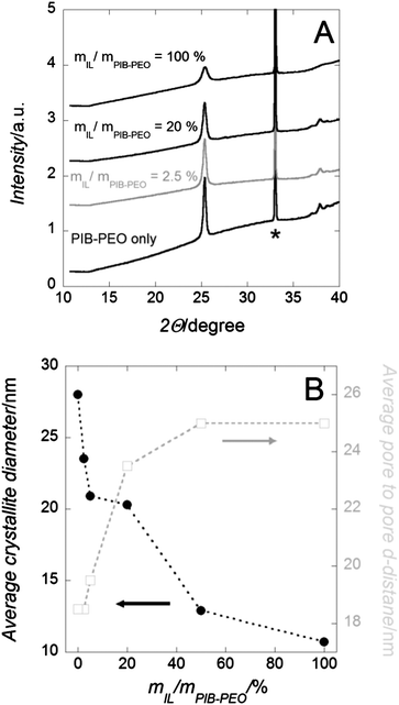 | ||
| Fig. 1 (A) WAXS patterns of mesoporous TiO2 films on Si wafer. (B) Anatase crystallite size and average pore-to-pore distance values. From (A): the reflections marked by a star are attributed to the Si wafer. The measurements were stopped at 2Θ = 40° due to the intense diffraction signal from the Si (100) wafer collected at higher angles. From (B): the average anatase crystallite sizes were calculated by Scherrer's equation from the anatase (101). | ||
The influence of the template quantity on the crystal size of anatase has already been previously studied, by varying the amount of PIB–PEO template to form mesoporous TiO2 films.13j Two possible effects were then postulated: (i) the higher the ratio of template to TiO2, the thinner the pore walls (thus anatase crystals) are (Fig. 1b). (ii) Surface active molecules and carbonaceous species obtained therefrom aggravate nucleation and possibly crystallization due to coverage of the surface.
All films were annealed simultaneously in the same oven and the films dip-coated on a similar surface area of Si wafers at the same withdrawal rate, so that the films contain quite similar amounts of metal oxide. After the film formation by the EISA method, fast annealing up to 600 °C is considered to be sufficient to obtain fully crystalline anatase mesoporous films.7 Fattakhova-Rohlfing et al. investigated the crystallinity of the monomodal mesoporous anatase film formed by a similar recipe and process as the ones we used.4b Even if the exact crystallinity of the matrix depends on the nature of the template used, annealing at 610 °C for thin mesoporous TiO2 films provides a matrix crystallinity of up to 90% according to this study.
2.2. Mesostructure
 | ||
| Fig. 2 TEM images of mesoporous anatase TiO2 film templated by PIB–PEO only (A) and (B) and by mIL/mPIB–PEO = 5% (C). | ||
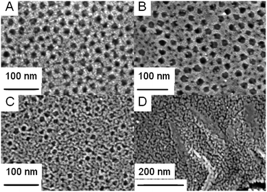 | ||
| Fig. 3 Top-view SEM images of mesoporous anatase–TiO2 film templated by PIB–PEO only (A), by mIL/mPIB–PEO = 5% (B), 100% (C) and IL only (D). | ||
 | ||
| Fig. 4 (A and B) Water adsorption–desorption isotherms (derived from EEP measurements) of mesoporous anatase films for different templating conditions. (C) Porous volume and average pore diameter evolution versus mIL/mPIB–PEO. (D) Pore size distribution (PSD) for a mesoporous anatase film templated by IL only, calculated from the water-adsorption branch of the corresponding isotherm. | ||
When the two porogen agents, PIB–PEO and C16mimCl, are used together, even for the smaller mIL/mPIB–PEO ratio, the mesoporous crystallized anatase–TiO2 films present a much narrower hysteresis than the film templated with PIB–PEO only (Fig. 4a and b). It certifies an increase of large mesopores connectivity. The evolution of the porous volume and the evolution of the pore size versus mIL/mPIB–PEO (Fig. 4c) show two different regimes:
- At low amounts of IL, 2.5% ≤ mIL/mPIB–PEO < 20%, the average pore size is ca. 20 nm and the porosity (defined as the porous volume with respect to the total volume of a film) is ca. 24.5%, while these values are respectively 17 nm and 20% when only PIB–PEO was used as the template. Sel et al.13f described a similar effect for a combination of C16mimCl/KLE, and the growth of the micelles of the amphiphilic block copolymers was attributed to the tendency of C16mimCl to enter the poly-ethylene-oxide (PEO) hydrophilic shell of the block copolymer, the templated mesopore thereby being increased and only several small wormlike pores are formed between the ellipsoidal pores (Fig. 3b and 5).
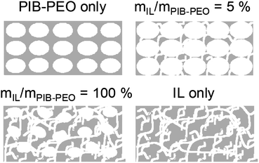 | ||
| Fig. 5 Schematic representation of the final anatase mesoporous films. | ||
- For ratios mIL/mPIB–PEO ≥ 20%, the average pore size decreases continuously while the overall porous volume continuously increases, simply because of the larger amount of the template present. Above a certain threshold concentration of IL, phase-separation from the block copolymer occurs, which results in the appearance of additional worm-like mesopores (Fig. 3c and 5). The pore size distribution becomes sharper and its maximum decreases to lower values when the ratio mIL/mPIB–PEO increases (Fig. S3†). It corresponds to a continuous increase of the contribution of the small mesopores to the mesoporous volume, as already seen in the slope of the water adsorption–desorption isotherm for mIL/mPIB–PEO ratios from 20% to 100%. Interestingly, the PIB–PEO templated mesopores themselves decrease in size with increasing amount of IL template. Films templated by mIL/mPIB–PEO = 100%, compared to films templated with PIB–PEO only, clearly present a smaller pore size than the ellipsoidal pores generated by PIB–PEO as seen in SEM images (Fig. 3b and c) and in the PSD calculated from EEP (Fig. S3†).
It has to be noticed that the EEP method was not able, in the present work, to make any evidence of the bimodal porosity when IL and PIB–PEO templates were both used, and it is in contradiction to direct observation with the SEM images (Fig. 3). We attribute this apparent contradiction to the difference in morphology between the worm-like and ellipsoidal mesopores and the small difference in their respective diameters (see ESI† for more detailed discussion).
The films produced with mIL/mPIB–PEO < 20% present GISAXS patterns similar to those of the anatase films templated with PIB–PEO only. The GISAXS patterns indicate a well-defined arrangement of mesopores, since even a second maximum is observed at Q = 0.52 A−1. These maxima can be interpreted either as a second order maximum or the oscillation of a form factor of uniform mesopores. Both interpretations are in compliance with a well-defined, regular mesostructure. A d-spacing of ca. 25 nm can be extracted from the first maximum, corresponding to the pore-to-pore distance of a cubic packing (Fig. 1b).13j,27 For larger ratios mIL/mPIB–PEO > 20%, the cubic pore packing of the block polymer micelles is increasingly disturbed, since the first GISAXS reflection is significantly wider. Also, the average pore-to-pore distance calculated from the position of the first Bragg interference (Fig. 6b) decreases from 23.5 nm to 19.5 nm and to 18.5 nm for mIL/mPIB–PEO = 20, 50 and 100%, respectively (Fig. 1b).
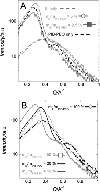 | ||
| Fig. 6 GISAXS patterns (in y-direction, see Fig. S4†) of mesoporous anatase films for different template ratios, mIL/mPIB–PEO ≤ 5% (A) and mIL/mPIB–PEO ≥ 20% (B). | ||
2.3. Film permeability
The measurements were conducted in a 50 mM aqueous hydrogen phthalate electrolytic solution (pH ∼ 4.2). Under such conditions crystallized metal oxide films can be considered as stable.8 Two different electrochemical probes displaying opposite charges were used, FeCN63− (anionic) and Ru(bpy)32+ (cationic), in order to take the possible electrostatic interactions with the surface of the metal oxide into account.17a The cyclic voltammetry (CV) method (Fig. 7 and S5†) was first applied to obtain qualitative information about the influence of the bimodal structure on the film permeability. The mass transport quantification of the different films was continued with the wall-jet electrochemical technique. A bare FTO electrode was used as the reference.(1) The films templated by PIB–PEO only (Fig. 7a and b) exhibited restricted response to both redox probes (lower peak current) and also hindrance to electron transfer with FeCN63− (higher peak potential separation).
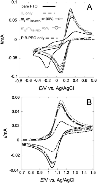 | ||
| Fig. 7 Cyclic voltammograms measured in the presence of 5 mM FeCN63− (A) or Ru(bpy)32+ (B) on the bare FTO electrode and FTO electrodes modified by thin mesoporous anatase films (thickness ∼ 110 nm). Legend for (A) and (B) is the same. | ||
(2) All the films templated by a mixture of IL and PIB–PEO exhibit quite similar response features, and the intensity of the peaks was quite close to that of bare FTO, indicating almost unhindered access to the back contact for the electron transfer.13g Electrochemical detection of the molecular probes at the modified FTO is probably restricted in the case of the thin films templated by PIB–PEO only, because of poor interconnection between the ellipsoidal mesopores, originating from pristine ideally spherical micelles.13g,j In the case of films using a mixture of the PIB–PEO and the IL as templates, the well connected mesoporous network (Fig. 3 and 5) facilitates the access to the FTO substrate for electrochemical detection.13g
For thicker films (thickness ∼ 240 nm) restrictions to electronic transfer from the redox probes to the FTO are not observed for the monomodal films (Fig. S5†). This could be explained by the presence of some nanometer-sized cracks previously described for such films.13j Note that the other characterization methods (SAXS, WAXS, EEP…) cannot distinguish between thick films (∼240 nm) and thin films (∼110 nm) with respect to the crystallite size and porosity. Possible structural differences between thick films (∼240 nm) and thin films (∼110 nm) are probably induced during the dip-coating process and annealing.
 | (1) |
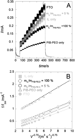 | ||
| Fig. 8 (A) Chronoamperograms (E = +1.5 V vs. Ag/AgCl) measured in the presence of 5 mM Ru(bpy)32+ under controlled flux (wall-jet configuration) on the bare FTO and FTO covered by different mesoporous anatase films, thickness ∼ 110 nm. (B) Linear data plotting 1/Ilimvs. 1/V3/4 of the corresponding chronoamperograms. | ||
A wall-jet electrode is defined as a planar electrode of known area (wall) and an imprinting flow of solution (jet) that provides well-defined hydrodynamics normal to the electrode. Ilim of a wall-jet electrode covered by a thin film can be expressed by eqn (2)
 | (2) |
In this equation v is the kinematic viscosity of the solution, α is the diameter of the solution jet, n is the electron stoichiometry for the electrochemical reaction of the redox probe, F is the Faraday constant, C is the concentration of the redox probe, Ds is the diffusion coefficient through the solution phase, V is the flow jet, r is the radius of the wall electrode, d is the film thickness, A is the electrode area, P is the partition coefficient, and Df is the diffusion coefficient through the thin film. Film permeability is defined as the molecular transport of the free species dissolved in the liquid phase through the porous network of the film. The film permeability is expressed as PDf, i.e. the product of Df and P.
Increasing the flow allows us to disregard the first term of the equation related to mass transport in solution (1/IMT). The second term of the equation is then easily determined by plotting 1/Ilimvs. 1/V3/4 (Fig. 8b), the first term of the equation being null at the intersection with the y axis. Note that two scenarios have been proposed in the literature to describe mass transport processes in thin films, through pinholes or through homogeneous membranes.29 Here it was assumed that only the latter model applied to the mass transport through the anatase films, as no visible defects and pinholes could be observed in the films with the available methods of characterization. The PDf values have been estimated on thin (∼110 nm, Fig. 9a) and thick films (∼240 nm, Fig. 9b). The rather homogeneous behaviour for different thicknesses validates the choice of the membrane model to describe the mass transport processes. Moreover, only small differences are observed between the variations in the permeability of the two electrochemical probes displaying opposite charges. As shown previously, FeCN63− anions display very low permeability through mesoporous silica thin films.13i,17a,25a By contrast, anatase films here restrict the permeability to negatively charged probes to a much lesser extent. It could be ascribed to the surface complexation of the anatase by phthalate species, modifying the surface charge of the titania. The dependence of PDf on mIL/mPIB–PEO (Fig. 9) shows that an optimum mIL/mPIB–PEO ratio exists whereby the most permeable mesoporous anatase film can be achieved for each of the two probes. Even for the lowest amount of IL (mIL/mPIB–PEO = 2.5%) the thinner films (∼110 nm) show an increase in their permeability of about one order of magnitude in comparison with the films templated by the PIB–PEO polymer only (Fig. 9a).
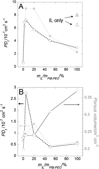 | ||
| Fig. 9 Evolution of the film permeability (PDf) versus mIL/mPIB–PEO for mesoporous anatase thin films possessing a thickness of ∼110 nm (A) and ∼240 nm (B). The pore volume evolution (squares) is issued from Fig. 4c. Redox probes are FeIIICN63− (diamonds) and Ru(bpy)32+ (grey dots). Triangles in (A) correspond to the permeability values of mesoporous films templated by IL only (the same color code for the redox probe used). Lines are used as a guide for the eyes. EEP and electrochemical measurements were all carried out on the same central position of the films corresponding to similar thicknesses contributing to the respective signals in the case of the thick films. | ||
We attribute this finding to the concomitant increase in large mesopore connectivity (see part 2.2.2.) and the conservation of good meso-ordering (see part 2.2.3.) ensuring an efficient percolation of the porous network through the film. However a possible influence of significant uncovered parts of the FTO surface cannot be ruled out.13g A slight increase in the IL concentration (5% < mIL/mPIB–PEO < 20%) enhances the pore connectivity and the accessibility of FTO correspondingly. When the amount of IL is increased further (mIL/mPIB–PEO > 5% with FeCN63− and >20% with Ru(bpy)32+ as redox probes) the film permeability is reduced. In the latter case, the packing of the mesopores is significantly disturbed (see part 2.2.3.) to compensate for the increase in porous volume and the percolation quality of the mesopores decreases significantly. Interestingly, the permeability of the monomodal films templated only by the IL is quite close to that of the most permeable bimodal films, suggesting that pores formed in this way are highly connected or can be long enough to span the entire film thickness. We note that the synthesis of crack-free anatase films templated with IL only is limited to thin films, thickness ≪ 200 nm (Fig. S6†).
The enhancement of permeability of the thicker films (∼240 nm) templated by IL and PIB–PEO is relatively small in relation to the thicker films templated by PIB–PEO only (Fig. 9b). As previously discussed (see part 2.3.1.), we assume that the anatase films templated with PIB–PEO contain a significant amount of nano-cracks. The addition of worm-like IL mesopores to favor the ellipsoidal mesopore percolation thus has a lower impact in this case than on the thinner films (featuring no micro-cracks). An optimum mIL/mPIB–PEO ratio allows the film permeability to be increased twice and 3.5 times for FeCN63− (ratio 5%) and Ru(bpy)32+ (ratio 20%), respectively (Fig. 9b). For mIL/mPIB–PEO > 20%, the permeability of the thick films drops because of the drastic disturbance of the packing of the large ellipsoidal mesopores. Large amounts of IL reduce the permeability of the films generated by IL and PIB–PEO templates even below the value of films generated by PIB–PEO only as the template (Fig. 9b). Because of the presence of macro-cracks (Fig. S6†) the thicker films (∼240 nm) using only C16mimCl as templates cannot be considered as homogeneous membranes, and thus the model by Massari et al. is consequently not applicable. Such macro-cracks have not been observed for the other films templated by PEO–PIB (only or mixed with IL).
2.4. Photovoltaic properties
A rather high UOC (around 760 mV) is observed for N719 sensitized anatase films templated by PIB–PEO only and anatase films templated by mIL/mPIB–PEO = 10% and 20% (Fig. 10), which is in good agreement with the values reported in the literature for TiO2 films (both nanoparticulate and dip-coated films) sensitized with various ruthenium dyes, ranging from 600 to 860 mV.30 A slightly lower average UOC value is found for the cells composed of the films templated by mIL/mPIB–PEO = 20% (Table 1). The short-circuit current density reaches its highest value of 1.055 mA cm−2 in the cells composed of the electrode templated by mIL/mPIB–PEO = 10%. Compared to the solar cells using an anatase electrode film templated by PIB–PEO only, the increase in photocurrent for films templated by using mIL/mPIB–PEO = 10% is explained by the higher dye loading (Table 1). It is caused by the higher film permeability and porous volume of the anatase films templated by mIL/mPIB–PEO = 10% (see part 2.2.1.).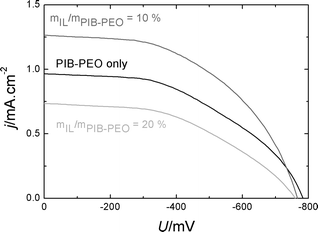 | ||
| Fig. 10 Comparison of j–U curves of N719 sensitized anatase films prepared by different template combinations. | ||
| j SC/mA cm−2 | U OC/mV | FF | η/% | Dye load/nmol cm−2 | |
|---|---|---|---|---|---|
| PIB only | 0.848 | −762 | 0.49 | 0.31 | 10.1 |
| m IL/mPIB–PEO = 10% | 1.055 | −759 | 0.47 | 0.37 | 11.2 |
| m IL/mPIB–PEO = 20% | 0.650 | −730 | 0.38 | 0.18 | 14.7 |
Compared to DSSCs with nanoparticulate TiO2 films, which generate jSC = 16 to 22 mA cm−2 with ruthenium sensitizers,31 the jSC value achieved with the bimodal anatase (mIL/mPIB–PEO = 10%) electrode appears rather small at first sight. It should be emphasized that our DSSC study was not intended to develop cells with high efficiency, but to utilize DSSCs as a suitable tool to address the influence of porosity on photoelectrochemical properties and dye loading.
If a comparison is made nevertheless, it has to be considered that our films have a thickness of about 110 nm, which is less than 1% of the typical thickness of the nanoparticulate films (ca. 12 mm)11 and which obviously cannot result in competitive performance parameters. Zukalová et al. reported a short-circuit current density of 2.7 mA cm−2 for mesoporous N945 sensitized TiO2 films from a similar dip-coating process to the one used in our study.3f The higher value of their films is explained by a greater thickness of approximately 270 nm3f as well as the red-shifted absorption maximum and higher extinction coefficient of the N945 dye compared to N719, which leads to ∼40% higher photocurrents in very thin films.30 Considering this fact, the films of Zukalová et al. would deliver approximately 1.9 mA cm−2 with N719 as the sensitizer. In comparison, our mesoporous anatase films templated by mIL/mPIB–PEO = 10% generate up to 66% of the corresponding photocurrent for an active film twice as thin. Since both films are very thin, an approximately uniform distribution of the light absorption throughout the film thickness can be assumed. This comparison proves that the anatase films with mIL/mPIB–PEO = 10% is a promising photoelectrode due to complete crystallization3d and high dye content. Note that the anatase film templated by PIB–PEO only generates about 50% of the photocurrent compared to the film of Zukalová et al.3f This finding is in good agreement with the difference in the film thickness and indicates a similar porosity and surface area if no IL template is used.
Surprisingly, the solar cells using the anatase films templated by mIL/mPIB–PEO = 20% exhibit the smallest photocurrents despite their further increased dye load. In principle, this may be explained by a lower electron collection efficiency or by a lower accessibility of the dye molecules to the electrolyte. In order to determine the electron collection efficiency ηcoll, we carried out Intensity Modulated Photocurrent Spectroscopy (IMPS) and Intensity Modulated photoVoltage Spectroscopy (IMVS) measurements (Fig. 11). With the frequencies found at the minima of each semicircle fmin the electron transport times τd (in the case of IMPS) and electron life times τn (in the case of IMVS) were calculated with eqn (3).32
 | (3) |
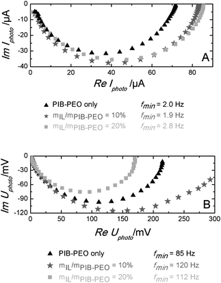 | ||
| Fig. 11 IMPS (A) and IMVS (B) spectra of N719 sensitized mesoporous anatase films, mIL/mPIB–PEO = 10% and mIL/mPIB–PEO = 20%. | ||
These values were used to calculate the electron collection efficiencies (Table 2) with the help of eqn (4).33
 | (4) |
| f min(IMPS)/Hz | f min(IMVS)/Hz | τ d /ms | τ n /ms | η coll/% | |
|---|---|---|---|---|---|
| PIB only | 85 | 2.0 | 1.87 | 79.6 | 97.6 |
| m IL/mPIB–PEO = 10% | 120 | 1.9 | 1.33 | 83.8 | 98.4 |
| m IL/mPIB–PEO = 20% | 112 | 2.8 | 1.42 | 56.8 | 97.5 |
The results clearly show that ηcoll is rather high and nearly constant for all three kinds of films, which rules out differences in ηcoll as a reason for the inferior performance of the anatase films templated by mIL/mPIB–PEO = 20%.
The electrochemical accessibility of the porous network in the different films was investigated by impedance spectroscopy. As an example, Fig. 12 shows a selection of typical impedance spectra of an anatase film templated by PIB–PEO only. The spectra exhibit a small semicircle at high frequency (i.e. at low resistance values), followed by a large semicircle at lower frequency, which starts to flatten at its low frequency end due to ion diffusion. Bisquert et al.34 attributed the high frequency semicircle in the impedance spectra of dye-sensitized solar cells to the counter electrode. The following small section of linear increase is due to electron diffusion in the porous TiO2 film and the second semicircle represents the electron transfer from the TiO2 film to the electrolyte. The resistance of the latter was found to increase towards more positive potentials (i.e. smaller voltages) due to the decreasing electron concentration in the TiO2 film, which is also the case in our results. However, fitting with the model by Bisquert et al. did not give satisfactory results. Much better fitting results were obtained with the simple model (Fig. 13) to represent the two observed semicircles.
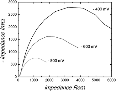 | ||
| Fig. 12 Typical impedance spectra of a mesoporous anatase film templated by PIB–PEO only measured at −800 mV, −600 mV and −400 mV. | ||
 | ||
| Fig. 13 Fitting model for the obtained impedance spectra, series connection of a series resistance (Rs) and two impedances consisting of a resistance (R1,R2) and a constant phase element (CPE1,CPE2) in parallel connection, respectively. | ||
The resistances R and capacities C obtained in the fits for the two semicircles are plotted against the cell voltage for all films (Fig. 14). It is obvious that R and C show no significant potential dependence in the case of the high frequency semicircle. This is generally the case for the impedance of the counter electrode. On the other hand, the observed R values are much too high to be explained by the resistance of the counter electrode, usually in the range of a few Ohms. For such a high resistance, the signal of the counter electrode seems to be hidden in a larger potential-independent impedance (appearing also at relatively high frequency). Such a phenomenon can be attributed to an electron back reaction from the conducting back contact or the contact impedance between the conducting back contact and the anatase film. It is clear, however, that this semicircle is not directly attributed to the anatase film.
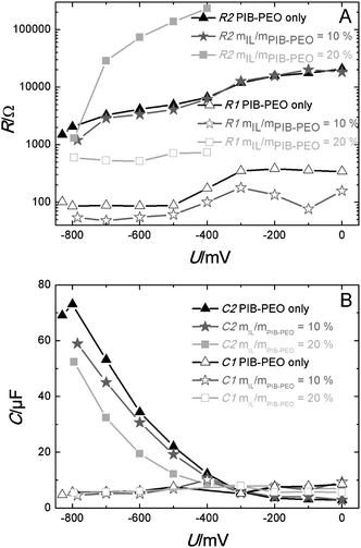 | ||
| Fig. 14 Dependencies of resistance (A) and capacity (B) for the first (R1 and C1) and the second semicircle (R2 and C2) of mesoporous anatase films PIB only, mIL/mPIB–PEO = 10% and mIL/mPIB–PEO = 20% on the potential. | ||
The R–U curves show that the resistances of the monomodal films and the bimodal films templated by mIL/mPIB–PEO = 10% are nearly equal, but the resistance for the anatase bimodal films templated by mIL/mPIB–PEO = 20% is significantly higher. This strongly indicates that a substantial part of the inner surface is not electrochemically accessible in the latter. In addition, it is most likely that the dye is confined in such a high quantity on the surface of the small pores that the redox electrolyte can hardly access it (pore blocking or dye aggregation).
3. Experimental section
3.1. Chemicals
Titanium tetrachloride (TiCl4) 99.9% was purchased from Aldrich, Ethanol absolute Normapur grade was purchased from Prolabo, Potassium hexacyanoferrate(III) (K3FeCN6) analytical grade was purchased from Fluka, potassium hydrogen phthalate (KHP) analytical grade was purchased from Merck, tert-butanol 99% was purchased from Riedel-de Haën, acetonitrile 99.9% was purchased from Carl Roth, tris(2,2′-nipyridine)ruthenium(II) chloride hexahydrate [Ru(bpy)3Cl2·6H2O] was purchased from Acros Organics, and the photosensitizer N719 was purchased from Dyesol. All aqueous solutions prepared for the permeability studies were prepared using high purity water (18 MΩ cm−1) from a Millipore milli-Q water purification system. The PIB–PEO polymer was provided by the BASF Company and C16mimCl was home-made.153.2. Preparation of initial solutions
The synthesis of a mesoporous TiO2 for mIL/mPIB–PEO = 5% is as follows. Preparation of the TiCl4 alcoholic solution was slightly modified from a previous recipe.13j A mixture of PIB–PEO-3000 (78 mg, Fig. S1†) and IL (3.9 mg) is dissolved in absolute EtOH (2.05 g) under sonication at 50 °C. After complete dissolution, the solution labeled solution “1” is left under magnetic stirring at ambient temperature for 5 minutes. In parallel, TiCl4 (0.52 g, 0.3 ml) is dissolved in absolute EtOH (2.05 g) under magnetic stirring under ambient conditions, and labeled solution “2”. After 5 minutes solution “1” is added slowly to solution “2” with magnetic stirring under ambient conditions. After 5 minutes deionized water (0.66 ml) is slowly added with stirring under ambient conditions, and the solution is stirred for 2 hours and then filtered (pore diameter is 0.2 μm) before use.The quantity of PIB–PEO-3000 is always constant in different recipes. The film templated only with the IL used an identical amount of IL to that of PIB–PEO-3000 alone, i.e. 78 mg.
3.3. Film preparation
Silicon wafers were previously heated at 550 °C for 5 hours (room atmosphere) and then washed with ethanol prior to use. Films were deposited on Si wafers or on FTO-covered glass at room temperature (20–22 °C) by dip-coating on substrates at constant withdrawal rates (1.5 and 5 mm s−1 to obtain thin and thick films respectively). The relative humidity inside the dip-coating chamber was controlled between 20 and 22%. The films were then put into a muffle oven at 80 °C for at least 20 min and annealed at 200 °C for 1 hour (ramp of 2 °C min−1), and then the films were calcined at 300 °C for 12 hours (ramp of 2 °C min−1). After calcination, the films were annealed up to 610 °C (ramp of 2 °C min−1 up to 500 °C, then 7 °C min−1 up to 610 °C) and were then removed immediately from the oven. The entire procedure is done in the same muffle oven in an ambient atmosphere.Crack-free dense films, references for EEP measurements, were prepared using a similar solution without any template. The dip-coating was conducted at a withdrawal rate <0.5 mm s−1.
3.4. Permeability investigations
All measurements were performed with a PGSTAT Autolab potentiostat/galvanostat (Eco Chemie) in a conventional 3-electrode cell. The TiO2–anatase mesoporous films deposited on FTO-covered glass were used as the working electrode. The surface of the electrode was delimited by an O-ring (1 mm thick and 9 mm inner diameter) on which a Teflon reservoir containing the electrolyte solution was placed. The uncovered surface electrode corresponded to the central part of each film, and the corresponding thickness was then either 240 ± 20 nm or 110 ± 10 nm when the films were formed for dip-coating withdrawal at 5 and 1.5 mm s−1 respectively (checked by profilometry). A Pt wire served as the counter electrode and an Ag/AgCl electrode (Metrohm) was used as the reference electrode. The experiment for quantitative analysis of permeability in the mesoporous thin films was carried out using a self-built wall-jet electrochemical setup.13i,17a,24,25 The probe solutions were operated for concentrations of 5 mM (K3Fe(CN)6 and Ru(bpy)3Cl2·6H2O) in a buffer solution of aqueous KHP (50 mM, pH ∼ 4.2).3.5. Dye adsorption
The anatase films were dried at 120 °C for one hour. Afterwards the films were sensitized in a solution of 0.5 mM N719 dye in acetonitrile–tert-butanol (50![[thin space (1/6-em)]](https://www.rsc.org/images/entities/char_2009.gif) :
:![[thin space (1/6-em)]](https://www.rsc.org/images/entities/char_2009.gif) 50) for 24 hours and dried at 80 °C for one hour.
50) for 24 hours and dried at 80 °C for one hour.
3.6. Cell preparation
Teflon tape (∼100 μm) with a circular cut-out of 5 mm in diameter, to define the active surface of the electrode, was used as the spacer between the dye-sensitized TiO2 electrode (deposed on FTO) and the transparent Pt-coated counter electrode (Dyesol, Pt-coated test cell TEC15 FTO glass). The circular cut-out was located on the upper part of the film dip-coated at a withdrawal rate of 1.5 mm s−1, the corresponding film thickness was 110 ± 10 nm. A sufficient amount of the redox electrolyte (Dyesol, EL-HSE, containing I−/I3− as the redox couple, 3-methoxypropionitrile as the solvent and an imidazole compound, inorganic and organic iodide salts as additives) was added between the electrodes.3.7. Photoelectrochemical measurements
The prepared DSSCs were illuminated through the dye-sensitized film with the white light of an Xe arc lamp filtered with an Oriel AM 1.5D filter (100 mW cm2). All measurements were performed with a Zahner IM6e electrochemical workstation. A green LED (530 nm, 10 mW cm-2 modulated with +/- 0.6 mW cm-2) served as light source for IMPS and IMVS. j–V curves were measured at four cells of each anatase electrode templated by PIB only, mIL/mPIB–PEO = 10% and 20%, respectively.3.8. Determination of the dye load
The N719 dye was desorbed from the sensitized TiO2 films in a solution of 0.1 M NaOH in ethanol–water (50![[thin space (1/6-em)]](https://www.rsc.org/images/entities/char_2009.gif) :
:![[thin space (1/6-em)]](https://www.rsc.org/images/entities/char_2009.gif) 50) for 30 minutes. The UV-Vis absorption spectra of the obtained dye solutions were measured with a Varian Cary 4000. The desorbed films were colorless.
50) for 30 minutes. The UV-Vis absorption spectra of the obtained dye solutions were measured with a Varian Cary 4000. The desorbed films were colorless.
3.9. Characterization
Grazing Incidence Small Angle X-ray Scatterings (GI-SAXS) were recorded on a Nanoviewer from Rigaku (CuKα radiation). The angle of incidence of the X-ray beam with respect to the film surface was set at 0.22°. Wide Angle X-ray Scattering (WAXS) measurements were performed using a PANanalytical (CuKα radiation). The EEP measurements were performed on an M2000 UV-visible (from 450 to 1000 nm) Variable Angle Spectroscopic Ellipsometer (VASE) from Woollam with an incidence angle of 70°. Data analysis was performed with the WVase32 software. Ellipsometric analysis of the crystallized mesostructured anatase films was performed immediately after the crystallization step at ambient temperature (25 °C) under dry air flux of relative humidity <2%. An assumption is that the optical properties of the matrix of porous and of dense materials are the same. The goal is to use the dense films as reference to determine the contribution of the anatase matrix to the refractive index of the porous films during the water adsorption–desorption steps. The EEP measurements consist of plotting the water adsorption–desorption isotherms from the variation of the film refractive index induced by the change of particle pressure of gas water above the film. The use of a pulsed air flow with controlled relative pressure of water allows a fast relative pressure equilibration for each point of the isotherm. Optical properties of porous films and dense films were obtained using a Cauchy model in the visible wavelength range for transparent films and a Lorentz model for light absorbing films.2,3d,17 The porous volume, Vp, is determined by EEP by fitting the volumetric fraction of air and of the titania matrix within the dry mesoporous film using the dense film as the reference.17bVwater absorbed/Vfilm is determined by fitting the volumetric fraction of the dry stabilized mesoporous film (dry conditions, pores are empty) and the water saturated mesoporous film (relative humidity = 98%, pores are filled by absorbed water) with the Bruggeman effective medium approximation (BEMA, eqn (5)). | (5) |
![[small epsilon, Greek, tilde]](https://www.rsc.org/images/entities/i_char_e0de.gif) A and
A and ![[small epsilon, Greek, tilde]](https://www.rsc.org/images/entities/i_char_e0de.gif) B within a volume unit of measured dielectric constant
B within a volume unit of measured dielectric constant ![[small epsilon, Greek, tilde]](https://www.rsc.org/images/entities/i_char_e0de.gif) (porous film). Vwater absorbed/Vfilm is then assumed to be expressed by eqn (6)
(porous film). Vwater absorbed/Vfilm is then assumed to be expressed by eqn (6) | (6) |
The pore size determination was based on a modified Kelvin, eqn (7)
 | (7) |
EEP experiments were performed three times with completely new sets of films each time. Both isotherms and pore size distributions are reproducible in each case.
The electron microscopy was performed using an HSEM 982 Gemini from LEO (SEM), and for the TEM pictures a CM30 STEM from Philips (presently FEI) was used.
4. Conclusions
The present study aimed at addressing a fundamental issue regarding mesoporous metal oxides, namely, the influence of pore connectivity on permeability. As the model material mesoporous TiO2 films were synthesized with distorted spherical mesopores of ca. 15 to 20 nm diameter, templated by a block copolymer of the PIB–PEO type, the connection of which can be varied by the addition of a second template, the long-chain ionic liquid (IL) C16mimCl, generating smaller mesopores in between the larger ones and influencing significantly the size of larger mesopores. The permeability was studied using redox probe molecules and suitable electrochemical measurements (wall-jet technique). Our study revealed that the variation of the relative amounts of the mesoporogen agents tends to greatly influence the mesopore networks of mesoporous anatase films. An optimal ratio between the surfactant ionic liquid and the amphiphilic block copolymer, 5% < mIL/mPIB–PEO < 50%, allows formation of anatase films with bimodal mesoporosity and a permeability at least double that of the reference mesoporous films templated with the amphiphilic block copolymer only. These permeability data were in full agreement with those obtained through characterization of the mesopore structure (GISAXS, EEP, electron microscopy), proving that the film exhibiting the highest permeability possessed an ordered arrangement of the larger mesopores, connected by a high concentration of mesopores of 8–10 nm size generated by the IL.When mesoporous anatase films templated by the combination of the surfactant ionic liquid and the amphiphilic block copolymer are used as the photoelectrode in a DSSC set-up, the solar energy conversion can be improved by 20% in comparison with the reference film templated with the amphiphilic block copolymer only. This finding is attributed to the 10% increase in dye loading. However, the films exhibiting the highest permeability and porosity (measured by EEP) do not present the best performance. This apparent paradox can be explained by the preferential localization of the dye in the small worm-like pores (ca. 8 to 10 nm in size) leading to reduced accessibility for the redox electrolyte.
We thus believe that these fundamental insights of the study are of general importance, as they not only demonstrate the possibility to improve film permeability and material loading by tuning the mesoporosity, but also scrutinize the limitations of hierarchical pore structures. These findings are therefore of relevance in applications where surface modification is a key factor, for instance in the case of DSSCs. Thus, our study helped to establish a general methodology to separate the impact of structural features of mesoporous films, namely pore volume, pore size, pore connectivity and surface area on transport-related properties such as permeability.
Acknowledgements
The authors thank Dr Simone Mascotto for his help and fruitful discussions and Günther Koch for his help with the TEM images. This work was supported by the Deutsche Forschungsgemeinschaft (DFG) (SM 199/6-1 and OE 420/5-1), Bundesministerium für Bildung und Forschung (BMBF, Germany, Förderkennzeichen 03X3525E, ”SOHyb” project). This project was supported by the Laboratory of Materials Research (LaMa) of JLU. In particular, the authors are indebted to the support of the PROCOPE French-German international collaboration program.Notes and references
- B. Chen and S. S. Mao, Chem. Rev., 2007, 107, 2891 CrossRef PubMed.
- (a) Y. Sakatani, D. Grosso, L. Nicole, C. Boissière, C. G. J. A. A. Soller-Illia and C. Sanchez, J. Mater. Chem., 2006, 16, 77 RSC; (b) J. Zhao, S. Sallard, B. M. Smarsly, S. Gross, M. Bertino, C. Boissière, H. Chen and J. Shi, J. Mater. Chem., 2010, 20, 2831 RSC.
- (a) B. O'Regan and M. Grätzel, Nature, 1991, 353, 737 CrossRef CAS; (b) M. Zukalová, M. Kalbáĕ, L. Kavan, I. Exnar and M. Graetzel, Chem. Mater., 2005, 17, 1248 CrossRef; (c) K. Hou, B. Tian, F. Li, Z. Bian, D. Zhao and C. Huang, J. Mater. Chem., 2005, 15, 2414 RSC; (d) E. Lancelle-Beltran, P. Prené, C. Boscher, P. Belleville, P. Buvat, S. Lambert, F. Guillet, C. Boissière, D. Grosso and C. Sanchez, Chem. Mater., 2006, 18, 6152 CrossRef CAS; (e) P. V. Kamat, J. Phys. Chem. C, 2007, 111, 2834 CrossRef CAS; (f) M. Zukalová, J. Procházka, A. Zukal, J. H. Yum and L. Kavan, Inorg. Chim. Acta, 2008, 361, 656 CrossRef PubMed.
- (a) Y.-G. Guo, Y.-S. Hu and J. Maier, Chem. Commun., 2006, 2783 RSC; (b) D. Fattakhova-Rohlfing, M. Wark, T. Brezesinski, B. M. Smarsly and J. Rathouský, Adv. Funct. Mater., 2007, 17, 123 CrossRef CAS; (c) P. G. Bruce, B. Scrosati and J.-M. Tarascon, Angew. Chem., Int. Ed., 2008, 47, 2930 CrossRef CAS PubMed; (d) H. Kaper, S. Sallard, I. Djerdj, M. Antonietti and B. M. Smarsly, Chem. Mater., 2010, 22, 3502 CrossRef CAS.
- C. Renault, V. Balland, E. Martinez-Ferrero, L. Nicole, C. Sanchez and B. Limoges, Chem. Commun., 2009, 7494 RSC.
- (a) M. Ogawa, Langmuir, 1997, 13, 1853 CrossRef CAS; (b) C. J. Brinker, Y. F. Lu, A. Sellinger and H. Y. Fan, Adv. Mater., 1999, 11, 579 CrossRef CAS.
- (a) E. L. Crepaldi, G. J. A. A. Soler-Illia, D. Grosso, F. Cagnol, F. O. Ribot and C. Sanchez, J. Am. Chem. Soc., 2003, 125, 9770 CrossRef CAS PubMed; (b) D. Grosso, G. J. A. A. Soler-Illia, E. L. Crepaldi, F. Cagnol, C. Sinturel, A. Bourgeois, A. Brunet-Bruneau, H. Amenitsch, P. A. Albouy and C. Sanchez, Chem. Mater., 2003, 15, 4562 CrossRef CAS; (c) B. Smarsly, D. Grosso, T. Brezesinski, N. Pinna, C. Boissière, M. Antonietti and C. Sanchez, Chem. Mater., 2004, 16, 2948 CrossRef CAS.
- (a) T. Brezesinski, D. Fattakhova-Rohlfing, S. Sallard, M. Antonietti and B. M. Smarsly, Small, 2006, 2, 1203 CrossRef CAS PubMed; (b) S. Sallard, T. Brezesinski and B. M. Smarsly, J. Phys. Chem. C, 2007, 111, 7200 CrossRef CAS.
- (a) P. C. Angelomé, L. Andrini, M. E. Calvo, F. G. Requejo, S. A. Bilmes and G. J. A. A. Soler-Illia, J. Phys. Chem. C, 2007, 111, 10886 CrossRef; (b) M. C. Fuertes, S. Colodrero, G. Lozano, A. R. Gonzales-Elipe, D. Grosso, C. Boissière, C. Sanchez, G. J. A. A. Soler-Illia and H. Miguez, J. Phys. Chem. C, 2008, 112, 3157 CrossRef CAS; (c) R. Ostermann, S. Sallard and B. M. Smarsly, Phys. Chem. Chem. Phys., 2009, 11, 3648 RSC.
- N. Krins, M. Faustini, B. Louis and D. Grosso, Chem. Mater., 2010, 22, 6218 CrossRef CAS.
- T. W. Hamann, R. A. Jensen, A. B. F. Martinson, H. Van Ryswyk and J. T. Hupp, Energy Environ. Sci., 2008, 1, 66 CAS.
- (a) T. Brezesinski, J. Wang, J. Polleux, B. Dunn and S. H. Tolbert, J. Am. Chem. Soc., 2009, 131, 1802 CrossRef CAS PubMed; (b) P. Wang, Y. X. Pang and S. N. B. Hodgson, J. Sol-Gel Sci. Technol., 2010, 54, 19 CrossRef; (c) J. M. Szeifert, D. Fattakhova-Rohlfing, D. Georgiadou, V. Kalousek, J. Rathouský, D. Kuang, S. Wenger, S. M. Zakeerudddin, M. Grätzel and T. Bein, Chem. Mater., 2009, 21, 1260 CrossRef CAS; (d) P. Hartmann, D.-K. Lee, B. M. Smarsly and J. Janek, ACS Nano, 2010, 4, 3147 CrossRef CAS PubMed; (e) H. Němec, P. Kužel, F. Kadlec, D. Fatthakova-Rohlfing, J. Szeifert, T. Bein, V. Kalousek and J. Rathouský, Appl. Phys. Lett., 2010, 96, 062103 CrossRef.
- (a) T. R. Pauly, Y. Liu, T. J. Pinnavaia, S. J. L. Billinge and T. P. Rieker, J. Am. Chem. Soc., 1999, 121, 8835 CrossRef CAS; (b) L. Huang, Z. Wang, J. Sun, L. Miao, Q. Li, Y. Yan and D. Zhoa, J. Am. Chem. Soc., 2000, 122, 3530 CrossRef CAS; (c) R. A. Caruso and M. Antonietti, Adv. Funct. Mater., 2002, 12, 307 CrossRef CAS; (d) C. M. Yang, B. Zibrowius, W. Schmidt and F. Schüth, Chem. Mater., 2003, 15, 3739 CrossRef CAS; (e) J. H. Sun, Z. Shan, T. Maschmeyer and M. O. Coppens, Langmuir, 2003, 19, 8395 CrossRef CAS; (f) O. Sel, D. Kuang, M. Thommes and B. Smarsly, Langmuir, 2006, 22, 2311 CrossRef CAS PubMed; (g) O. Sel, S. Sallard, T. Brezesinski, J. Rathouský, D. R. Dunphy, A. Collord and B. M. Smarsly, Adv. Funct. Mater., 2007, 17, 3241 CrossRef CAS; (h) S. Mascotto, D. Wallacher, A. Brandt, T. Hauss, T. Thommes, G. A. Zickler, S. S. Funari, F. A. Timmann and B. M. Smarsly, Langmuir, 2009, 25, 12670 CrossRef CAS PubMed; (i) M. Etienne, S. Sallard, M. Schröder, Y. Guillemin, S. Mascotto, B. M. Smarsly and A. Walcarius, Chem. Mater., 2010, 22, 3426 CrossRef CAS; (j) S. Mascotto, PhD thesis, Justus-Liebig-Universität, Germany, 2010.
- A. Thomas, H. Schlaad, B. Smarsly and M. Antonietti, Langmuir, 2003, 19, 4455 CrossRef CAS.
- (a) K. R. Seddon, A. Stark and M. J. Torres, Pure Appl. Chem., 2000, 72, 2275 CrossRef CAS; (b) Y. Zhou and M. Antonietti, Chem. Mater., 2004, 16, 544 CrossRef CAS; (c) T. Wang, H. Kaper, M. Antonietti and B. Smarsly, Langmuir, 2007, 23, 1489 CrossRef CAS PubMed.
- S. J. Gregg and K. S. W. Sing, in Adsorption, Surface Area and Porosity, Academic Press, London, 1982 Search PubMed.
- (a) M. Etienne, A. Quach, D. Grosso, L. Nicole, C. Sanchez and A. Walcarius, Chem. Mater., 2007, 19, 844 CrossRef CAS; (b) C. Boissière, D. Grosso, S. Lepoutre, L. Nicole, A. Brunet Bruneau and C. Sanchez, Langmuir, 2005, 21, 12362 CrossRef PubMed.
- P. Innocenzi, L. Malfatti, T. Kidchob and P. Falcoro, Chem. Mater., 2009, 21, 2555 CrossRef CAS.
- (a) A. Zürner, J. Kirstein, M. Döblinger, C. Bräuchle and T. Bein, Nature, 2007, 450, 705 CrossRef PubMed; (b) J. Kirstein, B. Platschek, C. Jung, R. Brown, T. Bein and C. Bräuchle, Nat. Mater., 2007, 6, 303 CrossRef CAS PubMed.
- T.-C. Wei and H. W. Hillhouse, Langmuir, 2007, 23, 5689 CrossRef CAS PubMed.
- C. Song and G. Villemure, Microporous Mesoporous Mater., 2001, 44–45, 679 CrossRef CAS.
- A. Walcarius, M. Etienne and B. Lebeau, Chem. Mater., 2003, 15, 2161 CrossRef CAS.
- A. M. Massari, R. W. Gurney, C. P. Schwartz, S. T. Nguyen and J. T. Hupp, Langmuir, 2004, 20, 4422 CrossRef CAS.
- M. Etienne, D. Grosso, C. Boissière, C. Sanchez and A. Walcarius, Chem. Commun., 2005, 4566 RSC.
- (a) A. Goux, M. Etienne, E. Aubert, C. Lecomte, J. Ghanbaja and A. Walcarius, Chem. Mater., 2009, 21, 731 CrossRef CAS; (b) Y. Guillemin, M. Etienne, E. Aubert and A. Walcarius, J. Mater. Chem., 2010, 20, 6799 RSC.
- R. Zieba, A. Traut, A. Seeber, C. Roeger-Goeppert, B. Smarsly, S. Sallard, C. Weidmann and J. Haetge, Patent WO201105487-A1, 2011.
- The present data do not allow us to claim the pore packing to be cubic, however we made this assumption based on the fact that body centered cubic packing has always been observed for the films templated with the block polymers KLE (ref. 4b, 7c, 8a, b, 12a and 13g) and PIB-PEO (ref. 13h and j).
- The potentials applied for the chronoamperometry are +1.5 V and −0.4 V vs. Ag/AgCl when Ru(bpy)32+ and K3Fe(CN)6 are used as probes respectively. We can then assume based on the CVs (Fig. 6 and S5†) that the electron transfer for the oxidation or the reduction of the probes at the surface of the FTO is not restricted. Moreover any significant reduction or oxidation of the anatase matrix from the top mesoporous film can be neglected in such conditions (Fig. S2†).
- A. J. Bard and L. R. Faulkner, in Electrochemical Methods: Fundamentals and Applications, John Wiley and Sons, New York, 2nd edn, 2000 Search PubMed.
- M. Zukalová, A. Zukal, L. Kavan, M. K. Nazeeruddin, P. Liska and M. Grätzel, Nano Lett., 2005, 5, 1789 CrossRef PubMed.
- M. Grätzel, Acc. Chem. Res., 2009, 42, 1788 CrossRef PubMed.
- A. C. Fisher, L. M. Peter, E. A. Ponomarev, A. B. Walker and K. G. U. Wijayantha, J. Phys. Chem. B, 2000, 104, 949 CrossRef CAS.
- G. Schlichthorl, N. G. Park and A. J. Frank, J. Phys. Chem. B, 1999, 103, 782 CrossRef.
- F. Fabregat-Santiago, G. Garcia Belmonte, J. Bisquert, A. Zaban and P. Salvador, J. Phys. Chem. B, 2002, 106, 334 CrossRef CAS.
- J. D. Bass, D. Grosso, C. Boissière and C. Sanchez, J. Am. Chem. Soc., 2008, 130, 7882 CrossRef CAS PubMed.
Footnote |
| † Electronic supplementary information (ESI) available. See DOI: 10.1039/c3nr02732e |
| This journal is © The Royal Society of Chemistry 2013 |
