
Research highlights
Adnan Memica, Anwarul Hasanbc, Mohsen Akbaribcd, Mehmet R. Dokmecibc and Ali Khademhosseini*bcde
aCenter of Nanotechnology, King Abdulaziz University, Jeddah, 21589, Saudi Arabia
bCenter for Biomedical Engineering, Department of Medicine, Brigham and Women's Hospital, Harvard Medical School, Cambridge, Massachusetts 02139, USA. E-mail: alik@rics.bwh.harvard.edu
cHarvard-MIT Division of Health Sciences and Technology, Massachusetts Institute of Technology, Cambridge, Massachusetts 02139, USA
dWyss Institute for Biologically Inspired Engineering, Harvard University, Boston, Massachusetts 02115, USA
eWorld Premier International – Advanced Institute for Materials Research (WPI-AIMR), Tohoku University, Sendai 980-8577, Japan
First published on 18th September 2013
Suspended microfluidics
So far most microfluidic systems have been built based on closed channels, minimizing their complexity, and avoiding in-depth understanding of the air-liquid interfaces and flows. However, more recently, microfluidic systems that include liquid–liquid and air–liquid interfaces have been gaining importance in the development of organ-on-chip platforms1 and high-throughput screening systems.2 The next natural step is to create open microfluidic systems that can enable new opportunities as well as be widely adaptable, accessible and simple.Recently, a system built on such a concept was reported by Beebe and colleagues,3 who demonstrated a proof-of-principle application of the idea of “suspended” microfluidics. In their system, capillary forces were used to generate microscale fluid flow in a microchannel that did not have a ceiling or a floor. Casavant et al.3 demonstrated that capillary flow could either be “hovering” between two or more air interfaces or “suspended” between air and a second immiscible liquid. The principle is based on generating spontaneous capillary flows within microchannels that are, for example, suspended between two air interfaces. This initial advancement of the flow is governed by the phenomena in which the energy reduction of the flow-solid surface area outweighs the energy increase related to the liquid–air interface area (Fig. 1).
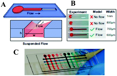 | ||
| Fig. 1 Spontaneous capillary flow describes fluid flow in a channel without a ceiling or a floor. (A) A suspended microfluidic channel with height (h) and width (w) that is open on the top and bottom surfaces can enable flow. (B) Prediction by the analytical model is validated experimentally. (C) Multiplexed screening chip with 4 × 10 array of μDots. Figure adapted and reprinted with permission from Casavant et al., Proc. Natl. Acad. Sci. U. S. A., 2013, 110, 10111–10116. | ||
In order to develop their suspended microfluidic platform, Casavant et al. used several design guidelines while introducing several key concepts. Most importantly, in order to generate the initial spontaneous capillary flow, it is necessary to have the ratio of wetted perimeter (pw) vs. free perimeter (pf), lower than the cosine of the contact angle of the fluid, where pf, represents the perimeter of the free (unbounded) surface, and pw represents the perimeter of the wetted surface at the cross-sectional plane of the channel. With this as the primary design criteria, the authors were able to reliably achieve spontaneous capillary flow of the suspended liquid in an open microfluidic device devoid of either a ceiling, a floor or both, powered by biphasic separation and surface energy minimization.
To make this technology widely useful, the researchers also showed that solvent resistant devices can be fabricated with relative ease without the need for exotic materials. The methods for generating the device were based on a combination of a parylene C chemical vapor deposition (CVD) step that would otherwise be challenging in an enclosed environment, preceded by a poly(dimethylsiloxane) (PDMS) or polystyrene fabrication, resulting in a device that is solvent-resistant.
The authors demonstrated the potential of their open microfluidic platform in several different applications. First, a multiplexed 3D screening platform was developed for assessing tumor cell biochemical responses to various cellular microenvironments. Second, they built a cellular invasion assay. In addition, they demonstrated the use of the suspended microfluidics as a microscale metabolomics platform of cultured cells. In contrast to standard microfluidic systems, suspended microfluidics provides a platform that is tubeless, passive, and creates biphasic flows ensuring that the solvent phase is always accessible regardless of its density, making it amenable to automation.
Suspended microfluidics is capable of generating spontaneous capillary flows and creating vertically separated liquid–liquid or air–liquid interfaces in a simple, robust, and precise manner. This approach represents a unique technological development that will significantly aid biological research, with the potential to render the technology widely accessible and easily integratable with high-throughput approaches.
High-throughput detection of rare cells
There is a growing need to detect, enrich and sort rare cells, particularly circulating tumor cells (CTCs), which are epithelial cells that have been released into blood from a primary tumor. CTC detection has the potential to improve patient outcomes, as their abundance has been related to metastasis potential. This detection should be possible at very low cell concentrations and requires high sensitivity and accuracy, both in clinical diagnostics and basic research settings. Various approaches to cell separation, including morphological, immunomagnetic, fluorescence and microfluidic based separations have been extensively studied over the past decades. However, each method is plagued with limitations, including low throughput, low accuracy or low yield of detection.4,5 Therefore, high-throughput detection of cells at low concentrations particularly with high efficiency remains a challenge. Recently, Savran and his group5 made a significant advancement by utilizing a micro-aperture chip system along with immunomagnetic cell separation that allowed them to obtain high throughput detection and separation of cancer cells at concentrations as low as a single cell per 1.25 mL of circulating fluid with consistently high accuracy and more than 90% detection yield.Chang et al.5 developed a simple microchip system based on a combination of size based immunomagnetic separation (Fig. 2). The microchip system consisted of a microfabricated silicon membrane placed in a PDMS fluidic chamber mounted on a hollow acrylic stand that contained a neodymium permanent magnet. The silicon chip included an array of through-holes (8 μm) larger than magnetic beads (1 μm) but smaller than target cells (10 to 30 μm). Magnetic beads were conjugated with antibodies against epithelial cell adhesion molecules (anti-EpCAM), facilitating the capture of target cells while flowing them through the device at a high speed.
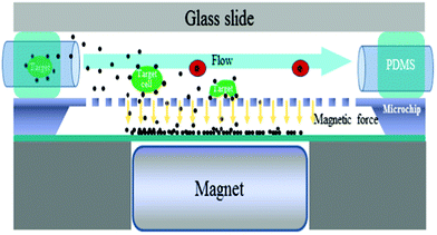 | ||
| Fig. 2 Micro-aperture chip system for high-throughput rare cell detection. Fluid containing magnetic bead-bound target cells flows at a high speed parallel to the chip. Target cells are attracted and held on the chip surface while free beads fall down to the bottom chamber. Captured cells can be imaged while in chamber or transferred elsewhere by terminating the magnetic field. Figure inspired by Chang et al.5 | ||
As the cell suspension passed through the fluidic chamber, in a direction parallel to the chip, the magnetic beads were attracted vertically downward due to the applied magnetic field. The individual beads that were not bound to any cells passed through the micro-apertures and were collected in the bottom chamber while the beads bound to the target cells became trapped in the upper chamber due to the larger size of the cells (Fig. 2). The trapped cells could then be imaged and analyzed inside the device or retrieved for subsequent culturing and analysis by removing the magnet, allowing the chip to be reused.
Overall experimental conditions were similar to other reports in the literature with the bead-cell incubation times ranging from 30 to 60 min for most combinations of parameters investigated. By using MCF-7 breast cancer cells at a density lower than a single cell (10 cells added to 12 mL) and up to 6.7 cells mL−1 (50 cells added to 7.5 mL), the authors were able to achieve more than 90% detection yield at flow rates that ranged from 1 to 4.3 mL min−1. The detection yield for A549 lung cancer cells decreased from 78% to 20% when the flow rate increased from 1 to 4.3 mL min−1. This decrease was attributed to the relatively low number of anti-EpCAM beads bound to the A549 cells, indicating that proper selection of a conjugated antibody and its affinity play an important role in detection. The re-culturing of retrieved cells in a petri-dish for up to five days after the isolation revealed that the cells were able to grow well despite prior treatment.
This novel method combines the benefits of microfluidics, immunomagnetic and size based separation methods in a single system, making it suitable for high-throughput detection of rare cells in very low concentrations. In addition, compatibility with existing protocols along with the relative simplicity and reusability of the micro-chip, could make the overall system highly useful in a wide range of clinical as well as environmental applications.
Capillary-based microfluidics: from paper to flocked substrates
Capillary-based microfluidic devices are powerful tools for point-of-care diagnostics and bioanalysis. These devices have recently gained interest for creating rapid diagnostic tests (RDTs) for low-resource settings because of their simplicity, compactness, ability to operate without external power, low fabrication cost, and simple readout mechanism.Arguably, the most popular material to construct these devices is functionalized paper as it is readily available, inexpensive, compatible with biochemicals and medical substances, and allows for transport of liquids without a need for an external power source. Paper-based microfluidics has now been extensively used to perform colometric assays and electrochemical sensing for improving health care and disease screening in developing countries.6 Due to the magnitude of the disease diagnostics market, other alternatives are currently being investigated. In one specific case, functionalized cotton threads have also drawn attention for creating low cost RDTs.7 The flexibility of cotton threads can be used to generate 2D and 3D patterns by means of traditional textile processes such as sewing, weaving, and knitting. Moreover, the threads tend to have a higher wetting ability compared to paper and are being explored for several applications.
In a recent study, Delamarche and colleagues used electroflocked substrates to create capillary-driven microfluidic networks.8 They fabricated these substrates by depositing charged microfibers on an adhesive-coated substrate (Fig. 3a). Hitzbleck et al.8 created a fluidic network, which consisted of a loading pad and three flow channels by simply using a scalpel (Fig. 3b). They showed that the flocked substrate wicked 23 μL of liquid per square centimeter of the substrate area. This value is comparable to the wicking capacity of currently available membranes which fall in the range from 16 μL cm−2 to 240 μL cm−2. Additionally, similar to paper and cotton threads, the flow of liquid in the flocked substrates follows Washburn's equation, which describes the flow in porous materials.
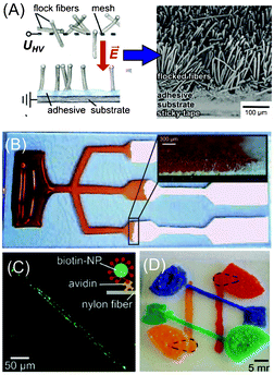 | ||
| Fig. 3 Flock-based microfluidics. (A) The process of manufacturing flocked substrates and an SEM image of a typical flocked substrate. (B) A typical microfluidic network formed from a flocked substrate to perform triple assays using capillary flow. The inset shows the filling front of colored water wicked through the flocked substrate. (C) Immobilized biotinylated nanoparticles on the flocked substrate as a proof-of-concept for performing lateral flow assays. (D) A 3D network of microchannels fabricated by subsequent stacking and flocking on a substrate. Figure adapted and reprinted with permission from Hitzbleck et al.8 Copyright © 2013 WILEY-VCH Verlag GmbH & Co. KGaA, Weinheim. | ||
An electroflocking process was used to deposit fibers with different properties. In one example, the group created wetting patterns by depositing hydrophobic and hydrophilic fibers using a shadow mask. These patterns can be used to guide liquid flow in a controlled manner. They also patterned biofunctionalized nylon fibers with avidin molecules on a flocked substrate using the same method. After immersing the substrate in a solution containing biotinylated nanoparticles and washing, the bound nanoparticles on the pattern became visible under a fluorescence microscope (Fig. 3c). To create sophisticated 3D networks, they subsequently stacked and flocked thin glass substrates (Fig. 3d). Multilayer 3D microfluidic networks have already been demonstrated using paper based platforms. However, establishing connections between the layers has been challenging as the holes between layers do not fill properly with liquids. One of the advantages for creating 3D networks with flock based fibers is that the holes between the layers can be filled with flock fibers that facilitate the propagation of fluids through the wetting mechanism.
Flocked substrates have been shown to be promising materials for creating capillary-based microfluidics. These materials have a wicking capacity in the range of paper-based materials. The manufacturing process is low-cost as flocked substrates with the size of a football field would approximately cost €80.8 The ability to pattern fibers with different properties facilitates the creation of complex 3D microfluidic networks with different functionalities for performing multiple bioassays. Therefore, flocked substrates can be potentially used as an alternative material for manufacturing RDTs for low resource settings.
References
- D. Huh, B. D. Matthews, A. Mammoto, M. Montoya-Zavala, H. Y. Hsin and D. E. Ingber, Science, 2010, 328, 1662–1668 CrossRef CAS PubMed.
- J. J. Agresti, E. Antipov, A. R. Abate, K. Ahn, A. C. Rowat, J.-C. Baret, M. Marquez, A. M. Klibanov, A. D. Griffiths and D. A. Weitz, Proc. Natl. Acad. Sci. U. S. A., 2010, 107, 4004–4009 CrossRef CAS PubMed.
- B. P. Casavant, E. Berthier, A. B. Theberge, J. Berthier, S. I. Montanez-Sauri, L. L. Bischel, K. Brakke, C. J. Hedman, W. Bushman, N. P. Keller and D. J. Beebe, Proc. Natl. Acad. Sci. U. S. A., 2013, 110, 10111–10116 CrossRef CAS PubMed.
- K. Hoshino, Y. Y. Huang, N. Lane, M. Huebschman, J. W. Uhr, E. P. Frenkel and X. Zhang, Lab Chip, 2011, 11, 3449–3457 RSC.
- C.-L. Chang, C. A. Savran, S. Jalal and D. E. Matei, Proceedings, IEEE Sensors, 2012, 1672–1675 Search PubMed.
- A. W. Martinez, S. T. Phillips, G. M. Whitesides and E. Carrilho, Anal. Chem., 2009, 82, 3–10 CrossRef PubMed.
- G. Zhou, X. Mao and D. Juncker, Anal. Chem., 2012, 84, 7736–7743 CrossRef CAS PubMed.
- M. Hitzbleck, R. D. Lovchik and E. Delamarche, Adv. Mater., 2013, 25, 2672–2676 CrossRef CAS PubMed.
| This journal is © The Royal Society of Chemistry 2013 |