 Open Access Article
 This Open Access Article is licensed under a Creative Commons Attribution-Non Commercial 3.0 Unported Licence
Cavity-enhanced optical trapping of bacteria using a silicon photonic crystal†
Thijs van Leest* and Jacob Caro
Kavli Institute of Nanoscience Delft and Department of Imaging Science and Technology, Delft University of Technology, Lorentzweg 1, 2628 CJ, Delft, The Netherlands. E-mail: m.m.vanleest@tudelft.nl
First published on 23rd August 2013
Abstract
On-chip optical trapping and manipulation of cells based on the evanescent field of photonic structures is emerging as a promising technique, both in research and for applications in broader context. Relying on mass fabrication techniques, the involved integration of photonics and microfluidics allows control of both the flow of light and water on the scale of interest in single cell microbiology. In this paper, we demonstrate for the first time optical trapping of single bacteria (B. subtilis and E. coli) using photonic crystal cavities for local enhancement of the evanescent field, as opposed to the synthetic particles used so far. Three types of cavities (H0, H1 and L3) are studied, embedded in a planar photonic crystal and optimized for coupling to two collinear photonic crystal waveguides. The photonic crystals are fabricated on a silicon-on-insulator chip, onto which a fluidic channel is created as well. For each of the cavities, when pumped at the resonance wavelength (around 1550 nm), we clearly demonstrate optical trapping of bacteria, in spite of their low index contrast w.r.t. water. By tracking the confined Brownian motion of B. subtilis spores in the traps using recorded microscope observations, we derive strong in-plane trap stiffnesses of about 7.6 pN nm−1 W−1. The values found agree very well with calculations based on the Maxwell stress tensor for the force and finite-difference time-domain simulations of the fields for the fabricated cavity geometries. We envision that our lab-on-a-chip with photonic crystal traps opens up new application directions, e.g. immobilization of single bio-objects such as mammalian cells and bacteria under controlled conditions for optical microscopy studies.
Introduction
Optical tweezers have become important tools in microbiology and biophysics for non-invasive studies of individual cells.1,2 For example, biophysical processes in the cell have been unravelled and closely related bacterial species have been identified, using the tweezers as a force probe3 or for immobilization of single cells and simultaneous Raman fingerprinting, respectively.4 Although highly valuable in research, optical tweezers are bulk optics instruments, costly and require expert operation. This limits their use in a broader context, e.g. for routine-type cell studies in biology and medicine or for sensing applications in the field. In this context and noting that optical tweezers are based on the gradient of the light intensity of a tightly focused laser beam, integrated photonics is presently attracting a lot of interest. The optical modes guided by waveguides, which are basic to photonic integrated circuits in silicon and other materials, possess an evanescent field with a strong gradient, which thus can be used to create a miniaturized on-chip optical trap operated in an aqueous environment. Waveguides have been applied already to trap (bio-)particles, at the same time using momentum transfer from the mode to the particle for propulsion along the waveguide.5–8 Another approach using two collinear waveguides is the dual-beam optical trap.9,10 Here, the intensity gradient is created by the beams launched from the waveguides into a fluidic channel. The great promise of these small waveguide-based traps derives from their mass producibility with techniques compatible with those in the semiconductor industry, enabling low cost sensors.The concept of integrated photonics for optical manipulation and trapping can be pushed further by the creation of isolated on-chip sites where the evanescent field is locally enhanced. Planar photonic crystals, which are dielectric waveguiding slabs with a submicron-scale periodic modulation of the refractive index and which form a versatile platform to control the flow of light,11 are highly suitable for this purpose. By introducing a well-defined defect in the crystal, acting as an optical resonator or cavity, a strongly enhanced local field is obtained with relatively low optical power. The evanescent field of the cavity mode, extending above the slab, has all the properties to form a strong local trap for single micro- and nanoparticles.12,13 For a one-dimensional (1D) photonic crystal cavity this has been proposed by Lin et al.14 and experimentally demonstrated in pioneering studies by the Erickson group15–18 and by Renaut et al.,19 polystyrene beads, protein molecules and nanorods being the trapped particles. For a two-dimensional photonic crystal, the cavity used so far is hollow,20 while the size of the trapped polystyrene bead should accurately match the cavity size. This seems disadvantageous for application-oriented trapping of bacteria, in view of their size distribution and the requirement for the cavity to be emptied.
Here, we demonstrate, for the first time, optical trapping of single bacteria with a cavity in a photonic crystal. We thus enter a new regime, by making the transition from synthetic particles and rods to these living bio-objects, which have an inhomogeneous index distribution and a considerably lower index contrast w.r.t. water. Effectively, only the thin bacterial cell wall proximal to the cavity, in view of its index of ≈1.42 (ref. 21) (implying a contrast of 0.09, to be compared with 0.26 for polystyrene), plays a role of importance for the optical force, making trapping much harder than for the synthetic particles. This important advancement, enabled by our detailed tailoring of the cavity properties in terms of mode coupling to the environment and resonance shift upon trapping for the specific index distribution of the bacteria, brings application to biologically relevant objects much closer. New directions that open up here are, among other things, on-chip optical microscopy studies of (the cycle of) a single cell, immobilized by trapping and thus not subject to the influence of a substrate or hindered by neighbouring cells, in a controlled nutritional environment or under the application of a drug or toxic agent.
The architecture of our devices comprises a cavity embedded in a planar silicon photonic crystal, in clear contrast to the 1D geometries of ref. 14–19 and, as argued below, is scalable to obtain multiple parallelism, so that a fluidic lab-on-a-chip can be equipped with many trapping sites. An artist impression closely resembling a real device with a single cavity is given in Fig. 1a, where a trapped bacterium is sketched. We combine our photonic crystal trap with microfluidics, so that the resulting lab-on-a-chip enables the control of both the flow of light and water on the scale required for single cell studies.
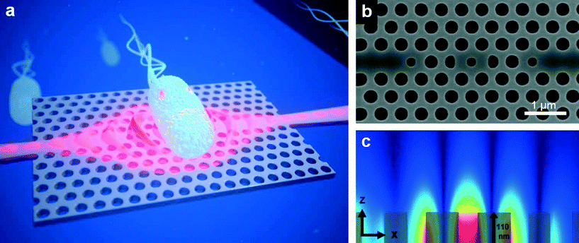 | ||
Fig. 1 (a) Impression of a photonic crystal with a cavity for optical trapping. The red wavelike structure depicts the strongly enhanced evanescent field of the cavity mode that bulges out of the slab, exerting force on a bacterium. (b) SEM picture of an H1 cavity, which has a central hole smaller than the regular holes. Adjacent to this hole two other modified holes are seen. For the actual devices the size of these holes has been optimized with nanometre-scale precision to obtain the required properties for trapping. Outside these holes there are the photonic crystal waveguides. The smaller holes even more outwards provide for the required coupling to the photonic crystal waveguides. (c) Mode profile of the cavity, showing the amplitude of the electric field |![[E with combining right harpoon above (vector)]](https://www.rsc.org/images/entities/b_i_char_0045_20d1.gif) | in a vertical plane through the central x-axis, with in grey the upper half of the central Si parts. The evanescent field is clearly visible. | in a vertical plane through the central x-axis, with in grey the upper half of the central Si parts. The evanescent field is clearly visible. | ||
The enhanced evanescent field of the cavity may also induce a Raman spectrum of the trapped bio-object, just like the Raman laser tweezers of ref. 4. This follows from the expression for the modal energy of a cavity, given by Ecav = (Q∥/2)Pin/ωres (see ESI†), where Q∥ is the in-plane quality factor of the cavity, Pin is the power supplied to the cavity and ωres is the resonance frequency of the cavity. Inserting the numbers (ESI†), and including the fraction of the modal energy in the evanescent field (≈3.5%), it follows that the energy available for excitation of the Raman effect in a trapped bacterium is about a factor of ten higher than for a tightly focused laser beam of the same power. This combination of trapping and Raman thus has high potential for a lab-on-a-chip for fast and label-free identification of bio-objects for e.g. monitoring the quality of drinking water and analyses in health and medicine. Such applications can be anticipated from the recent demonstration of tumour cell identification by means of Raman spectroscopy in combination with fibre based optical traps and microfluidic environments22 and from the general capabilities of optical manipulation using near field photonics.23
Device design and architecture
We selected the H0, H1 and L3 cavities, widely used for their light-confinement properties.24–26 They are embedded in a 220 nm thick silicon photonic crystal with a triangular lattice of holes of reduced radius r/a = 0.3 (r = hole radius, a = lattice constant, a = 430–470 nm). The crystals have a TE band gap for telecom-wavelengths, i.e. for the polarization parallel to the slab they are opaque for in-plane light with a wavelength around 1550 nm, where the cavity resonances are placed. The H0 cavity is formed by modifying two adjacent holes, while the basic geometry of the H1 cavity is a hole of reduced size. The L3 cavity is a line defect of three removed holes, of which we use the fundamental resonant mode. Fig. 1b is a scanning electron microscope (SEM) picture of a photonic crystal with an H1 cavity. Fig. S1 (ESI†) gives detailed SEM pictures of the three fabricated cavities, which have as-measured quality factors of about 2300. Fig. 1c is a plot of the mode profile of an H1 cavity in a vertical plane through its centre. It can be seen clearly that the modal field of this cavity is strongest in the central hole. The evanescent part of the mode, used here for trapping of bacteria, extends several hundred nanometres above the slab.The architecture is characterized by optical access to the H1 cavity (and similarly to H0 and L3) via two collinear photonic crystal waveguides, which are long line defects in the crystal. The waveguide sections closest to the cavity are seen in Fig. 1b. These waveguides go over into ridge waveguides, which extend to the edge of the chip. To excite the cavity resonance, it is fuelled with laser light from the edge of the chip via one of the waveguides, the other waveguide being available for measurement of in-plane light transmission through the cavity. A fluidic channel crossing the photonic crystal is created on-chip using a dry film resist technique.27 The complete fabrication process and the experimental set-up for optical trapping are described in the ESI.†
In Fig. 2 we plot the mode profiles in the x–y plane 6 nm above the surface (the distance taken between a trapped spore and the Si surface; see paragraph on calculation of the trapping forces), obtained with the finite-difference time-domain (FDTD) software of Lumerical.28 For each cavity the profile is superimposed on the hole pattern. The mode of H0, H1 and L3 has two, three and seven dominating lobes or hot spots, respectively, which all are inside the projected contour (dashed circle) of the bacterial spores we use in this study. The lobes resemble the focus of a conventional laser trap, so that they may act as individual traps for particles smaller than the inter-lobe distance and thus smaller than used here.
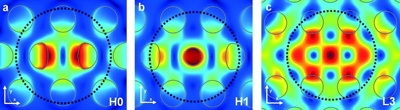 | ||
| Fig. 2 Simulated mode profile of the H0 (a), H1 (b) and L3 (c) cavity, showing the amplitude of the electric field || in a plane 6 nm above the surface. The dashed circles indicate the contour of a 1.06 μm diameter model of a bacterial spore trapped at the cavity. The holes of the photonic crystal cavity geometries are marked in grey. | ||
We envision that this architecture of photonic crystal waveguides and a cavity, known already from studies of wave guiding, light manipulation and light confinement, will also form a versatile platform for photonic sensing. Using the particle-size dependence of the optical force (F ∝ volume), particles in a fluidic flow can be sorted by waveguides and guided towards cavities operating as sites for immobilization and Raman fingerprinting. Repeated branching out of photonic crystal waveguides via Y-splitters29 enables fuelling of light to many cavities in the crystal. In this way, for example attributing a 5 × 5 μm2 footprint to a single cavity and its immediate vicinity, a 100 × 100 μm2 area can accommodate up to 400 trapping sites. The assembly can be completed with on-chip lasers, which can be integrated monolithically or heterogeneously, depending on the material system of the photonic crystal.
Experiments
In the experiments we use two types of bacteria with different wall structures, viz. Bacillus subtilis and Escherichia coli. These are well-known Gram-positive (wall structure of lipid layer surrounded by sugar layer) and Gram-negative bacteria (wall structure of two lipid membranes separated by peptidoglycan), respectively. The B. subtilis and E. coli bacteria are rod shaped (cross-sectional area ≈ 1 × (3–5) μm2). B. subtilis is used in the form of both vegetative cell and spore. The spores are employed because of their highly defined size, shape and index distribution (see section on trap stiffness), which make them ideal biological model particles for our quantitative studies, both in simulations and experiments.Culturing and preparation of the bacteria are described in the ESI.† The size of the bacteria is much smaller than the fluidic channel height of 30 μm, implying that we did not optimize the probability that a bacterium enters the evanescent field of a cavity. This is compensated by a bacterium concentration of about 108 ml−1, high enough to obtain trapping within a minute and low enough to avoid disturbance of the observations on a trapped bacterium by other bacteria. The height of a channel optimized for the trapping probability will be about two times the particle size, allowing a much lower concentration.
We clearly observe optical trapping of single bacteria by each of the three cavities when they are pumped at the resonance wavelength. In a sequence for a typical trapping event, the bacterium is supplied to the cavity by the water, which typically flows at about 5 μm s−1. When coming in reach of the evanescent field of the cavity mode, it becomes trapped at the cavity. The optical force is that strong that it can overcome the drag force of the flowing water. Once trapped, we observe that the bacterium is hovering above the cavity. This indicates that the trapped particle undergoes confined Brownian motion in the attractive potential of the trap and that it does not adhere to the surface. The latter aspect is confirmed when the light supply to the cavity is switched off: immediately the bacterium is released back into the water flow. Without interruption of the light supply, a bacterium can be kept trapped for a long time (>5 min). Trapping events for vegetative B. subtilis (L3, H0, H1) and for E. coli (H1) are shown in Movie 1 (ESI†). In Fig. 3 we give snapshots of Movie 1, showing trapping of a vegetative B. subtilis at an L3 cavity. Trapping of B. subtilis spores is shown in Movie 2 (ESI†).
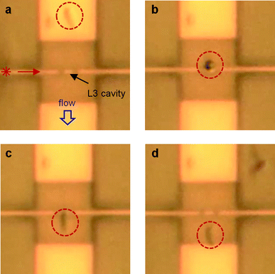 | ||
| Fig. 3 Snap shots of Movie 1 for a rod shaped vegetative B. subtilis, showing trapping by an L3 cavity. The cavity is centred in the photonic crystal, which is the central square in each picture. In (a) the bacterium (in the dashed circle) streams along with the flow, towards the cavity. In (b) the bacterium is trapped by the cavity at its front, where it was initially captured. The snap shot was taken at the moment the bacterium is oriented vertically, while flipping over in the flow. In (c) the bacterium is oriented along the stream lines, while being trapped at the cavity. By switching off the laser (d), the bacterium is released back into the flow. Due to diffraction limitations, the photonic crystal holes cannot be discerned. The contrast between bacteria and background has been enhanced for better visibility of the bacteria. Further details of this trapping event can be observed in Movie 1 in the ESI† and are discussed in the text. | ||
In general, trapping of the rod-shaped bacteria does not happen at a preferential part. However, in a steady flow these bacteria tend to align along the stream lines, so that one end of the bacterium reaches the cavity first and trapping occurs at that end. It may then happen that the bacterium flips over in the flow, while the temporary higher drag force cannot disrupt it, so that it remains attached at the end where it was initially captured. This behaviour is observed in the part of Movie 1 (ESI†) corresponding to Fig. 3.
The Brownian motion of a trapped bacterium can be studied via the light–matter interaction. For example, by changing the optical power coupled to a cavity, the extent of the excursions of the bacterium from the trap centre is changed, as we observed with a microscope. These changes arise from modification of the confinement potential. This control of the Brownian motion is made quantitative in the discussion related to Fig. 4a, b and e, f. Further, in the measured power transmitted through a cavity we observe temporal fluctuations. We interpret these power fluctuations as fluctuations in the dielectric perturbation of the cavity by the bacterium, induced by its Brownian motion and in turn leading to fluctuations in the resonance wavelength of the cavity. Similarly, Mandal et al., also monitoring the transmitted power, have observed a step in the output signal of the bus waveguide in coincidence with a trapping event of a polystyrene bead at the cavity.15
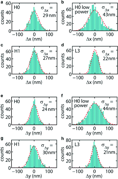 | ||
| Fig. 4 Histograms of the displacement of a trapped B. subtilis spore from the centre position (i.e. centre of the scatter plot in the x–y plane), for the cavities as indicated. (a–d) Displacements in the x-direction, (e–h) displacements in the y-direction. | ||
For the spores, at the device-input side, we also observe trapping of bacteria on the photonic crystal waveguide, induced by its evanescent field. This is illustrated in Movie 2, ESI.† For the waveguide mode, the integral of the Poynting vector over a plane perpendicular to the waveguide is non-zero. This results in a scattering force that propels the spore along the waveguide up to the cavity, where it encounters the tunnel barrier that confines the cavity mode. The bacterium then crosses the barrier, implying that the enhanced field of the cavity mode is strong enough to pull it across, whereafter it further resides at the cavity. Occasionally, for the L3 cavity and for low power, we observe hopping of a spore between two positions of the cavity (Movie 2, ESI†). We identify these positions with lobes of the cavity mode that induce metastable sub-traps. These findings with the spores give an impression of more general manipulation, sorting and immobilization functionalities for bio-objects that may be realized with this planar photonic crystal architecture.
The cavities have been optimized30 for trapping of bacteria, using FDTD simulations. These comprise optimization of the modal energy, implying a high quality factor, with the underlying goal of obtaining strong gradients of the modal evanescent field. A condition for stable trapping is that the trapping induced resonance shift, i.e. the shift of the cavity resonance induced by the perturbation of the trapped particle, should not exceed the resonance width.13 In short, our approach starts with reduction of radiation losses from the cavity. Then, in-plane coupling to the cavity is added, using two symmetrically positioned photonic crystal waveguides. This coupling is optimized, keeping track of the condition for maximum modal energy (see ESI†) and the resonance shift induced by positioning a 1 μm diameter model bacterium in proximity of the cavity. In this way we arrive at the aforementioned value of the quality factor of about 2300, for the three cavities. When we replace the model bacterium by the index distribution describing the B. subtilis spores used here for quantitative analyses (see below), the resonance shifts change only slightly, so that modification of the designs is not needed.
Trap stiffness
In order to obtain the trap stiffness of the cavities, we study the Brownian motion of trapped spores of B. subtilis in more detail. These spores are close to spherical, and their index distribution is accurately known.31–33 Adopting the results of ref. 31 and 33 and using size measurements of our spores with an optical microscope, we thus arrive at the following model for the spores: a 1.06 μm diameter sphere with a 75 nm thick coat of index ncoat = 1.39, which mainly consists of proteins, and with a core of index ncore = 1.51, which contains the chromosomal DNA and has a diverse composition. We note that in this model we have replaced the slightly ellipsoidal shape of the spores by a spherical shape with an effective diameter.We follow the Brownian motion by tracking the position of a single trapped spore in time, by deriving its position in the x–y plane for successive frames of a movie, without relying on fluorescent labelling as done in ref. 15 and 19. The procedure we developed includes determination of the spore area and data correction for video-image motion blur34 (see Movie 3 and details in the ESI†). In Fig. 4a–h we show, for the three cavities, histograms of the displacement of a trapped spore from the centre position in the trap, which coincides with the cavity centre. The optical power presented to a cavity (procedure to estimate the power in the ESI†) is given in Table 1, along with other data. For each histogram we draw a Gaussian probability density function defined by the root mean square displacements σΔx and σΔy (given in the panels) calculated from the raw data. As can be seen, a Gaussian function, which applies to a harmonic confinement potential expected for an optical force obeying Hooke's law, describes the histograms very well. Thus, in spite of the spore probing more than a single lobe of the cavity mode (see Fig. 2, where the dashed circles indicate the spore size), the potential effectively behaves harmonically. The motion blur correction function34 for these data takes values in the range 0.78–0.93, yielding the true values σΔx(Δy),true listed in Table 1. For these power levels σΔx(Δy),true is several tens of nanometres, with an estimated uncertainty of ≈10%. For H0 we find that decreasing the power from 0.50 to 0.32 mW (see Fig. 4a, b and e, f) gives an increase of σΔx(Δy),true from about 33(29) nm to about 46(48) nm, reflecting weaker confinement of the spore. The resulting normalized experimental trap stiffnesses kx(y),exp, derived from σΔx(Δy),true = (kT/kx(y))1/2 (kx(y) = trap stiffness, not normalized) and from the estimated power presented to each cavity, are listed in Table 1 as well. We note that the experimental stiffnesses are rather comparable, among the traps and among the directions, the average being 7.6 pN nm−1 W−1, although for L3 smaller values are obtained for either direction. This stiffness is very comparable to the experimental stiffness of the 1D resonators in ref. 15 for 200 nm polystyrene beads (5.9 and 5.6 pN nm−1 W−1 for the two directions). This seems reasonable, since the spores are larger than the beads and at the same time have a lower index, which gives compensating effects in the force. The normalized stiffnesses of the cavities are about two orders of magnitude higher than those of conventional laser tweezers.2 This indeed confirms that the confined and resonantly enhanced field results in very strong trapping forces.
| P (mW) | σΔx,true (nm) | σΔy,true (nm) | kx,exp (pN nm−1 W−1) | ky,exp (pN nm−1 W−1) | kx,calc (pN nm−1 W−1) | ky,calc (pN nm−1 W−1) | |
|---|---|---|---|---|---|---|---|
| H0 | 0.50 | 33 | 29 | 8.6 | 11.8 | 9.2 | 14.1 |
| 0.32 | 46 | 48 | 6.6 | 6.1 | 9.2 | 14.1 | |
| H1 | 0.43 | 32 | 34 | 11.1 | 9.4 | 5.6 | 15.4 |
| L3 | 1.2 | 28 | 27 | 3.6 | 3.8 | 3.1 | 6.4 |
To put the values of the experimental trap stiffness in perspective, we have calculated this quantity via the Maxwell stress tensor,35 which yields the optical force exerted on a spore at a particular position. In our procedure we subtract the force on the empty integration cube from the force on the integration cube with a spore inside, for improved accuracy (see ESI†). The fields of the cavity modes are obtained with the Lumerical software.28 This features sub-meshing, which we use for high resolution in critical regions, in particular the cavity mode, both in the slab and in the range of the evanescent field, where the trapped spore resides (see ESI†). The separation between the model spore and the surface of the slab is taken as 6 nm. We arrive at this estimate based on the surface roughness observable in electron microscope images of B. subtilis spores32 and on the closest approach expected for a Debye-screened repulsive electrostatic potential between particle and surface for the ion concentration in the medium (25 mmol l−1 NaCl). In the calculations the device geometries as measured from SEM pictures are used.
The calculated forces Fx and Fy for displacements Δx and Δy, respectively, are plotted in Fig. 5. For each cavity the forces are close to linear for displacements 0 nm ≤ Δx, Δy ≤ 100 nm, in agreement with Hooke's law already found experimentally. From linear fits to the data points in this range we obtain the stiffnesses kx(y),calc listed in Table 1. The values are close to the experimental ones (on average within 30%), a very good result in view of the many steps involved in the calculations.
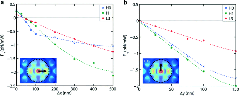 | ||
| Fig. 5 Calculated optical forces acting on a B. subtilis spore for the three cavities, for 1 mW of presented optical power, for displacements in the x-direction (a) and the y-direction (b). In (a) and (b) the lines in the interval 0 nm ≤ Δx, Δy ≤ 100 nm are linear fits to the data points, while for Δx, Δy > 100 nm lines have been drawn to guide the eye. | ||
Systematically, ky,calc exceeds kx,calc. This is explained from the mode structures (Fig. 2), which each have several lobes centred on the x-axis. For small Δx the spore thus is attracted by several lobes (two, three and three lobes for H0, H1 and L3, respectively). Put differently, the spore interacts with an overall potential resulting from the potentials of individual lobes, giving a more flat landscape in the x- than in the y-direction and thus a smaller force in the x-direction. For L3 flattening occurs in both directions, but to a lesser extent in the y-direction than in the x-direction. The range of relative flatness of the overall potential in the y-direction is therefore smaller than in the x-direction. For H0 the force curve flattens for Δx > 100 nm. This is understood from the property that the force is increasingly dominated by a single lobe instead of by two lobes. These arguments are reminiscent of the work of Zemánek et al.,36 who studied optical trapping of polystyrene beads in a 1D optical lattice in water, in dependence of the number of intensity maxima the bead is overlapping with.
We see that for each cavity Fy(0) = 0 and Fx(0) > 0. Part of the positive force Fx(0) arises from the absence of perfect cancellation of calculation errors in the surface integral of the Maxwell tensor over the cube enclosing the spore, due to symmetry breaking induced by the applied light flux. Another part, we suggest, may be a net scattering force exerted by the evanescent field of this light flux at the position of the cavity. In Fy(0) these effects leading to a non-zero force are absent. For H0 and H1 and for Δy > 100 nm we also see flattening for Fy(Δy). This makes sense, since when shifted in the y-direction the spore has an increasingly weaker interaction with the dominant lobes of the cavity modes. kx,calc and ky,calc of L3 are clearly smaller than those of H0 and H1, in good agreement with the experimental finding. This arises from the weaker evanescent field of L3,30 which naturally gives a smaller force. In addition, there is the afore-mentioned flattening effect of multiple lobes on the potential in either direction.
An estimate of the trapping force for vegetative bacteria is very hard to make, whether it is from the Brownian motion or from calculations, due to the rough and ill-defined cell boundary, the variation in size and shape, pili branching out and the motility. However, a lower bound of the force in the y-direction can be set by balancing it with the drag force exerted on the bacterium by the flow. Operating at a flow of about 5 μm s−1 and with a bacterium in the trap, the optical power is decreased to the level where the bacterium is released. The actual flow at the fluid level of the bacterium is measured from its position in successive frames of a movie. The drag force is determined using Faxen's law37 for a 1 μm diameter spherical particle near a surface. As a result we find for the three cavities and both for B. subtilis and E. coli that the trapping force is at least about 0.2 pN mW−1, which does not contradict the results for the spores. In reality this number will be considerably higher in view of the above-mentioned properties of the vegetative bacteria, which all will increase the drag force.
Conclusion
In conclusion, we have clearly observed cavity-enhanced optical trapping of B. subtilis and E. coli bacteria using photonic crystals, which have a low index contrast w.r.t. water and consequently are hard to trap. Among our findings are a comparable capability of the three cavities studied to trap rod shaped, motile bacteria and almost spherical, dormant bacterial spores, and a power dependence of the confined Brownian motion of B. subtilis spores in the traps. Quantitative analysis of the Brownian motion of the spores yields strong trap stiffnesses around 7.6 pN mW−1 nm−1, the values for the H0 and H1 cavity being comparable, but for the L3 cavity somewhat, yet distinctively, lower. This difference arises from the cavity-mode structures. The trap stiffnesses agree very well with values we have calculated from the Maxwell stress tensor. The calculated force curve of H0 for the x-direction shows an interesting piecewise smooth behaviour, the transition point between the two branches originating from the specific mode structure for this cavity. Our results qualify these traps as immobilization centres of bacteria and other small bio-objects for lab-on-a-chip sensors, for example for drinking water technology and health and medicine. With added Raman spectroscopic functionality provided by the enhanced evanescent field, this may lead to a sensor for identification of the trapped object.Acknowledgements
The authors gratefully acknowledge the financial support of Wetsus, the Dutch centre of excellence for sustainable water technology. They further acknowledge B. van der Gaag of Kiwa Water Research for stimulating discussions and S. Stallinga, B. Rieger and L. J. van Vliet for making available their tracking software and for advice on image pre-processing. Fabrication was carried out in the Kavli Nanolab Delft. R. Hoogerheide designed and fabricated the holder of the fluidic chip. Bacteria cultures were kindly provided by the Kluyver Laboratory of Delft University of Technology, where the authors also received expert advice in selecting bacterial species and handling the bacteria.Notes and references
- A. Ashkin and J. M. Dziedzic, Science, 1987, 235, 1517–1520 CAS.
- K. C. Neuman and S. M. Block, Rev. Sci. Instrum., 2004, 75, 2787–2809 CrossRef CAS PubMed.
- D. A. Koster, V. Croquette, C. Dekker, S. Shuman and N. H. Dekker, Nature, 2005, 434, 671–674 CrossRef CAS PubMed.
- C. Xie, J. Mace, M. A. Dinno, Y. Q. Li, W. Tang, R. J. Newton and P. J. Gemperline, Anal. Chem., 2005, 77, 4390–4397 CrossRef CAS PubMed.
- S. Kawata and T. Tani, Opt. Lett., 1996, 21, 1768–1770 CrossRef CAS PubMed.
- S. Gaugiran, S. Gétin, J. Fedeli, G. Colas, A. Fuchs, F. Chatelain and J. Dérouard, Opt. Express, 2005, 13, 6956–6963 CrossRef CAS PubMed.
- B. S. Schmidt, A. H. Yang, D. Erickson and M. Lipson, Opt. Express, 2007, 15, 14322–14334 CrossRef CAS PubMed.
- A. H. J. Yang and D. Erickson, Nanotechnology, 2008, 19, 045704 CrossRef PubMed.
- M. M. van Leest, F. Bernal Arango and J. Caro, J. Eur. Opt. Soc., Rapid Publ., 2011, 6, 11022 CrossRef.
- O. G. Hellesø, P. Løvhaugen, A. Z. Subramanian, J. S. Wilkinson and B. S. Ahluwalia, Lab Chip, 2012, 12, 3436–3340 RSC.
- J. D. Joannopoulos, S. G. Johnson, J. N. Winn and R. D. Meade, Photonic Crystals: Molding the flow of light, Princeton University Press, Princeton, 2nd edn, 2008 Search PubMed.
- A. Rahmani and P. C. Chaumet, Opt. Express, 2006, 14, 6353–6358 CrossRef PubMed.
- M. Barth and O. Benson, Appl. Phys. Lett., 2006, 89, 253114 CrossRef.
- S. Lin, J. Hu, L. Kimerling and K. Crozier, Opt. Lett., 2009, 34, 3451–3453 CrossRef PubMed.
- S. Mandal, X. Serey and D. Erickson, Nano Lett., 2010, 10, 99–104 CrossRef CAS PubMed.
- X. Serey, S. Mandal, Y. F. Chen and D. Erickson, Phys. Rev. Lett., 2012, 108, 048102 CrossRef PubMed.
- Y. F. Chen, X. Serey, R. Sarka, P. Chen and D. Erickson, Nano Lett., 2012, 12, 1633–1637 CrossRef CAS PubMed.
- P. Kang, X. Serey, Y. F. Chen and D. Erickson, Nano Lett., 2012, 12, 6400–6407 CrossRef CAS PubMed.
- C. Renaut, J. Dellinger, B. Cluzel, T. Honegger, D. Peyrade, E. Picard, F. de Fornel and E. Hadji, Appl. Phys. Lett., 2012, 100, 101103 Search PubMed.
- N. Descharmes, U. P. Dharanipathy, Z. Diao, M. Tonin and R. Houdré, Lab Chip, 2013, 13, 3268–3274 RSC.
- H. C. Ren, F. Vollmer, S. Arnold and A. Libchader, Opt. Express, 2007, 15, 17410–7423 CrossRef PubMed.
- S. Dochow, C. Krafft, U. Neugebauer, T. Bocklitz, T. Henkel, G. Mayer, J. Albert and J. Popp, Lab Chip, 2011, 11, 1484–1490 RSC.
- D. Erickson, X. Serey, Y.-F. Chen and S. Mandal, Lab Chip, 2011, 11, 995–1009 RSC.
- H. H. J. E. Kicken, I. Barbu, R. W. van der Heijden, F. Karouta, R. Nötzel, E. van der Drift and H. W. M. Salemink, Opt. Lett., 2009, 34, 2207–2209 CrossRef CAS PubMed.
- M. Loncar, M. Hochberg, A. Scherer and Y. Qiu, Opt. Lett., 2004, 29, 721–723 CrossRef CAS PubMed.
- Y. Akahane, T. Asano, B. S. Song and S. Noda, Nature, 2003, 425, 944–947 CrossRef CAS PubMed.
- N. Wangler, L. Gutzweiler, K. Kalkandjiev, C. Muller, F. Mayenfels, H. Reinecke, R. Zengerle and N. J. Paust, J. Micromech. Microeng., 2011, 21, 0960–1317 CrossRef.
- Lumerical FDTD Solutions, Inc., http://www.lumerical.com/tcad-products/fdtd/ (accessed Jan. 21, 2013).
- R. Wilson, T. J. Karle, I. Moerman and T. F. Krauss, J. Opt. A: Pure Appl. Opt., 2003, 5, S76–S80 CrossRef CAS.
- T. van Leest, J. T. Heldens, B. van der Gaag and J. Caro, Photonic crystal cavities for resonant evanescent field trapping of single bacteria, in Biophotonics: Photonic Solutions for Better Health Care III, Proceedings of SPIE 8427, Brussels, April 16–19, 2012 Search PubMed.
- P. S. Tuminello, E. T. Arakawa, B. N. Khare, J. M. Wrobel, M. R. Querry and M. E. Milham, Appl. Opt., 1997, 36, 2818–2824 CrossRef CAS PubMed.
- A. Driks, Microbiol. Mol. Biol. Rev., 1999, 63, 1–20 CAS.
- A. Katz, A. Alimova, M. Xu, P. Gottlieb, E. Rudolph, J. Steiner and R. Alfano, Opt. Lett., 2005, 30, 589–591 CrossRef CAS PubMed.
- W. Wong and K. Halvorsen, Opt. Express, 2006, 14, 12517–12531 CrossRef PubMed.
- J. D. Jackson, Classical electrodynamics, New York, Wiley, 3rd edn, 1998, p. 261 Search PubMed.
- P. Zemánek, A. Jonás and M. Liska, J. Opt. Soc. Am. A, 2003, 19, 1025–1034 CrossRef.
- E. Schäffer, S. F. Nørrelyke and J. Howard, Langmuir, 2007, 23, 3654–3665 CrossRef PubMed.
Footnote |
| † Electronic supplementary information (ESI) available: Details of the fabrication procedure, the experimental and simulation methods are provided, including the estimate of the input power. Movie 1 shows several examples of trapping events with vegetative B. subtilis and E. coli using the H0, H1 and L3 cavities. Movie 2 shows trapping of B. subtilis spores and demonstrates photonic crystal waveguide-based transport of a spore towards a cavity. Movie 3 is an example of the tracking analysis performed on pre-processed movie frames, showing a spore in the trap of the H0 cavity including its cross-marked centre. Movies are played 0.1–0.5 times slower than real-time. See DOI: 10.1039/c3lc50879j |
| This journal is © The Royal Society of Chemistry 2013 |