 Open Access Article
 This Open Access Article is licensed under a
 Creative Commons Attribution 3.0 Unported Licence
Microfluidic platforms for mechanobiology
William J.
Polacheck†
a,
Ran
Li†
b,
Sebastien G. M.
Uzel†
a and
Roger D.
Kamm
*ab
aDepartment of Mechanical Engineering, Massachusetts Institute of Technology, 77 Massachusetts Avenue, Cambridge, MA 02139, USA
bDepartment of Biological Engineering, Massachusetts Institute of Technology, 77 Massachusetts Avenue, Cambridge, MA 02139, USA. E-mail: rdkamm@mit.edu; Tel: +1-617-253-5330
First published on 4th April 2013
Abstract
Mechanotransduction has been a topic of considerable interest since early studies demonstrated a link between mechanical force and biological response. Until recently, studies of fundamental phenomena were based either on in vivo experiments with limited control or direct access, or on large-scale in vitro studies lacking many of the potentially important physiological factors. With the advent of microfluidics, many of the previous limitations of in vitro testing were eliminated or reduced through greater control or combined functionalities. At the same time, imaging capabilities were tremendously enhanced. In this review, we discuss how microfluidics has transformed the study of mechanotransduction. This is done in the context of the various cell types that exhibit force-induced responses and the new biological insights that have been elucidated. We also discuss new microfluidic studies that could produce even more realistic models of in vivo conditions by combining multiple stimuli or creating a more realistic microenvironment.
 Roger D. Kamm Roger D. Kamm | Roger Kamm (center right) is the Cecil and Ida Green Distinguished Professor of Mechanical and Biological Engineering and head of the MIT Mechanobiology Lab. His research spans fundamental studies of mechanotransduction to design of microfluidic systems for 3D co-culture and drug screening. William Polacheck (center left), Ran Li (right), and Sebastien Uzel (left) are graduate students in the Mechanobiology Lab. William is developing microfluidic platforms for investigating mechanotransduction of interstitial fluid stresses by tumor cells, Ran studies co- and tri-culture microfluidic platforms for investigating the effects of tumor microenvironment on cancer cells, and Sebastien is developing 3D microfluidic models for recapitulating neuromuscular junction formation and function. |
Introduction
Microfluidic assays have become increasingly important in the quest to understand how cells of various tissues sense and respond to mechanical stimuli, termed mechanotransduction (Fig. 1a) Often, the mechanical stimulus is externally imposed, as in the case of fluid shear stress, but we also consider effects that are associated with intracellular tensions generated by active cell contraction in the absence of external forces. Prior to the explosive growth of this new technology, enabled by the development of soft lithographic methods,1 most of the work had been conducted using traditional cell culture methods. While extremely valuable, these methods were not without their limitations. Many studies were conducted on rigid, planar substrates rather than in a more realistic 3D, compliant microenvironment. Also, while methods had been developed to subject the cells to various types of mechanical stimulus (e.g., cyclic strain or fluid shear stress), there were limits on the extent to which one could exert precise control over the multiple factors that influence cellular responses.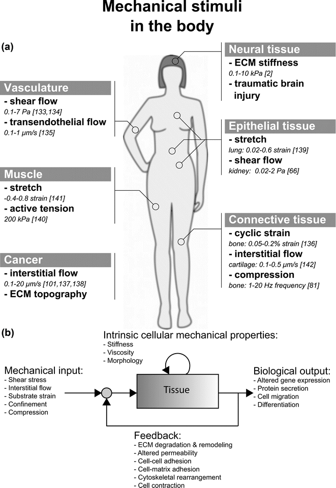 | ||
| Fig. 1 (a) Illustration of mechanical stimuli found in various tissues inside the body. The in vivo quantity of each of these stimuli is also listed. (b) Mechanotransduction is the process by which cells transduce mechanical inputs into biological responses. This process is initiated by mechanical stimuli (shear stress, interstitial flow, or substrate strain), which elicit biological responses or outputs (altered gene expression, protein secretion, cell migration) from cells and tissues. These biological responses may involve changes to intrinsic cellular mechanical properties, such as the stiffness of the cytoskeleton. Furthermore, when the biological response involves changes to the mechanical properties of the cell or tissue, these changes influence the effect of the mechanical input on the cells and tissue. Thus, mechanotransduction often involves a feedback process. For example, fluid shear stress (mechanical input) causes gut epithelial cells to polarize and elongate (biological output), which alters the fluid flow profile and in turn, the shear stress imparted on the epithelial monolayer (feedback).79 | ||
We view mechanotransduction as a process of stimulation (mechanical input) that elicits a response from the cell (biological output), which can alter the intrinsic mechanical properties of the cell, as depicted in Fig. 1b. Furthermore, the biological output can change the cellular microenvironment (nearby cells and ECM), altering the initial mechanical input. This feedback response is often ignored but is critical in determining the overall response of a living tissue to mechanical stimuli.
With the advent of microfluidics came the capability to better regulate the conditions that contribute to a mechanotransduction response, and also to observe that response in 3D, at high magnification and in real-time. And while the methods are still evolving, this is an appropriate point at which to assess these new capabilities, examine how they have advanced our understanding, and to identify where the field is headed as new functionalities are developed.
This review is organized around the tissues or cell types known to respond to mechanical stimulus and the microfluidic assays developed to probe the associated biological responses (Fig. 1a). We also discuss some of the biological insights that have been gained from microfluidic assays, but do not attempt to provide a detailed comparison with the results from other, more traditional assays. These have been the focus of several excellent reviews in the recent literature.2–4 Since the field is still in flux, we include discussion of the limitations of current systems and ways in which they might be improved. Our emphasis on tissue types as an organizing principle distinguishes the present review from a number of others on related topics. See, for example, Kurth and co-workers for a review that focuses more on the types of device but with less emphasis on the biological insights that microfluidics provides;5 Kshitiz et al. for studies of stem cells in microfluidics;6 for 3D culture methods see Huh and colleagues.7 Single cell studies are not covered in detail here but have been reviewed recently by Zheng et al.;8 Vanapali and co-workers and Hou et al. review the use of microfluidics in the context of cell mechanics, including the considerable body of work on cell separation processes.9,10 Finally, for a comprehensive review of MEMS technologies more broadly in mechanotransduction, see Kim et al.11
Vasculature
Shear flow
Vasculature is comprised of endothelial cells (ECs) that line the inner surface of the blood vessels, stromal cells (smooth muscle cells and pericytes) that surround the outer surface of the vessels, and blood cells (erythrocytes, leukocytes, monocytes, platelets) that travel within the vessels. Inside the body, all of these cells are subjected to various mechanical stimuli such as hemodynamic forces and solid stresses. Among these stimuli, the most important hemodynamic force encountered by ECs is shear stress generated by blood flow. Experiments in macroscale systems such as parallel plate flow chambers12 have demonstrated that fluid shear stress influences EC proliferation, migration, permeability, morphology, and gene expression.13 Although these macroscale systems have contributed much to our understanding of how endothelial cells respond to shear flow, they are often difficult to customize and require large volumes of reagents and high cell numbers. In addition, these macroscale systems generally have low experimental efficiency since only one shear stress level is typically generated in each apparatus. To address these issues, many microfluidic shear flow assays have been developed.14–17 Specifically, to increase experimental efficiency, some of these microfluidic assays were designed so that multiple shear stress levels can be simultaneously applied to ECs cultured in a single chip.15,16 For example, Song et al. reported a multi-channeled shear flow assay that allows for the simultaneous generation of different levels of pulsatile shear stress in each channel.15 Pulsatile shear stress, typical of arterial blood flow, was generated by an array of Braille pins that drive flow through the elastic PDMS microchannel. Using this system, the authors were able to achieve average shear stresses of up to 1.2 Pa. A more recent microfluidic system further increased the throughput of shear flow experiment by allowing ten different non-pulsatile shear stress levels (0.07–13 Pa) to be generated on a single chip.16 Using these systems, the authors reported elongation and alignment of ECs with shear flow for both pulsatile15 and non-pulsatile flow,16 as well as an increase in von Willebrand factor secretion by ECs with increasing shear stress magnitude16 (Table 1 and Fig. 2). In addition to these two systems, other microfluidic platforms were designed to produce spatially resolved shear stress gradients within a single microchannel by tapering the channel dimensions.18,19 These platforms were used to investigate the effects of a continuous range of shear stresses and shear stress gradients on ECs cultured in a single microchannel.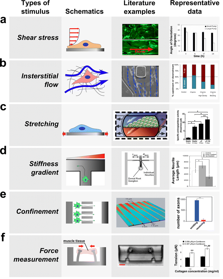 | ||
| Fig. 2 Microfluidic devices have been developed to investigate the biological responses of cells and tissues to various mechanical stimuli. Schematics (left) and the images (center) of microfluidic devices developed to study the effect of mechanical stimuli are shown along with typical biological responses to each stimulus (right). (a) Fluid flow through confined channels imparts shear stress on cells cultured within microfluidic devices. Such platforms have allowed investigation of the effect of physiologic shear stress on endothelial cells, which align the cells in the direction of flow (right, modified from van der Meer et al.17 and Song et al.15). (b) Applying a fluid pressure gradient across a hydrogel allows the investigation of the effect of interstitial flow on cell migration and alignment. For example, interstitial flow (blue arrow) was applied to cancer cells seeded within a collagen hydrogel (left and center), and this platform allowed elucidation of parameters that govern upstream and downstream migration in response to flow (modified from Polacheck et al.103). (c) By incorporating flexible substrates into microfluidic platforms, devices have been developed to study the effect of mechanical stretch on the cells cultured on the deformable substrate. For example, gut epithelial cells were cultured as a monolayer on top of a PDMS membrane, which is deformed by applying suction in the lateral channels, and cyclic strain causes cells to assume a more physiologically relevant phenotype (right, modified from79). (d) Gradients in stiffness of a substrate within a microfluidic device were used to study the effect of stiffness gradient on axon outgrowth; axons preferentially grow into the direction of decreasing stiffness (right, modified from Sundararaghaven et al.49). (e) A microfluidic system was used to study the effect of geometric confinement on axon outgrowth. In this example, axons were allowed to grow into microgrooves of decreasing width. This microgroove confines the growth of an axon in the direction of decreasing width (left and center), and the number of axons growing from the narrow side to the wide side (red) is much lower than the number of axons growing in the opposite direction (blue, modified from Peyrin et al.62). (f) Devices have been developed to measure force generated by mechanically active cells and tissues. In this example, cardiac microtissue was grown around two micro-cantilevers. As the muscle tissue contracted, it displaced the cantilevers, which was used to measure the force generated by muscle tissue (left and center, modified from Legant et al.122). Among other results, this study revealed that an increase in the stiffness of the cantilevers can lead to an increase in tension exerted by the cells. | ||
| Stimulus | Cell type | Magnitude | Response | Sources |
|---|---|---|---|---|
| Shear stress | Endothelial cells | 0.07–13 Pa | Cell elongation | 15,16,21–23,27 |
| Cell alignment parallel to flow direction | ||||
| Altered migration direction | ||||
| Increase ROS, vWF production | ||||
| Increased cell contractility | ||||
| Decrease permeability of blood vessel | ||||
| Platelets | 0.05–5 Pa | αIIbβ3-dependent reduced platelet adhesion to fibronectin | 40 | |
| Erythrocytes | 0.4–3.3 Pa | ATP release | 41,42 | |
| Bone | 0.007–0.24 Pa | Osteoblast differentiation from precursor cells | 68,83 | |
| Shear magnitude-dependent calcium influx in osteoblasts | ||||
| Lung | 10 Pa (air-liquid interface) | Cell death and detachment | 73 | |
| Kidney | 0.1 Pa | Apical-basal polarity | 67,69 | |
| Actin cytoskeleton rearrangement | ||||
| Trafficking of Aquaporin-2 to cell membrane | ||||
| Increased NH3 production, increased glucose consumption | ||||
| Interstitial flow | Endothelial cells | Transendothelial: 2.5–35 μm s−1 | Angiogenic sprouting for basal-apical flow | 30,31 |
| Interstitial flow: 1.7–11 μm s−1 | Vasculargenesis and formation of vascular networks with well-defined lumens | 34 | ||
| Cancer cells | 0.1–4.7 μm s−1 | Autologous chemotaxis downstream | 102–104 | |
| Fluid-stress induced migration upstream | ||||
| Substrate strain | Kidney epithelium | ∼7% | Intracellular Ca2+ influx | 76 |
| Cardiomyocytes | 10% uniaxial strain, 1 Hz | Decreased expression of α-MHC | 120 | |
| Stem cells | 5% stretch, 1 Hz | Stress fibers align parallel to the direction of stretch | 36 | |
| Substrate strain & shear stress | Lung | 5–15% substrate strain at 0.2 Hz, 0.01 Pa shear stress | Surfactant secretion | 78 |
| Decreased alveolar barrier permeability | ||||
| Physiologic neutrophil arrest on endothelium and diapedesis through alveolus to epithelial lumen | ||||
| Gut | 10% substrate strain at 0.15 Hz, 0.002 Pa shear stress | Increased permeability of epithelial monolayer | 79 | |
| Polarized cell phenotype | ||||
| Formation of villi-like structres with positive mucin 2 staining | ||||
| Maintained barrier function with gut bacteria co-culture | ||||
| Confinement | Neurons | 3 μm high × 10 μm wide | Single axon elongation inside grooves | 53 |
| Cancer cells | (3–12) × (6–100) × 600 μm in PDMS | Rapid, directionally persistent migration | 107 | |
| (3–30) × (3–30) × 150 μm in collagen type I | Protease-independent migration | 108 | ||
| Endothelial cells (substrate) | 100–200 μm wide micropatterned lines | ECs with polygonal morphology migrate in a triphasic fashion, switching between upstream and downstream migration | 23,24 | |
| Compression | Neurons | 65 Pa (hippocampal) – 540 Pa (DRG) maximum pressure before injury | Focal axonal swelling, altered axonal transport, and altered mitochondrial distribution preceded loss of function | 56 |
| Stiffness | Neurons | 57–797 Pa – gradients ∼0.5 Pa/um | Axon outgrowth towards softer regions | 49 |
| Force measurement | Skeletal muscle cells, cardiomyocytes | 0.2–0.45 mN mm−1 post stiffness | Higher force generated with higher stiffness | 122,124,125 |
| -Force generated: ∼6–11 μN (passive tension), 1–6μN (additional tension upon activation) | ||||
| Flow generation | Cardiomyocytes | 0.2–2 nL min−1 (theoretical 0.5 μL min−1) | Beat frequency and fluid particle displacement a function of culture temperature and duration | 127–129 |
In addition to increasing the efficiency of shear flow experiments, many microfluidic platforms have been designed to closely mimic the perturbed shear flow conditions thought to contribute to diseases such as atherosclerosis. For example, Estrada et al. reported a microfluidic system that models the disturbed flow conditions often associated with atherosclerotic lesions. Using this model, the authors found that a disturbed/reversing shear flow waveform (maximum shear stress = 0.75 Pa, minimum shear stress = −0.44 Pa, and average shear stress = 0.13 Pa) decreased β-catenin expression and the alignment of ECs to the flow direction compared to normal/non-reversing arterial flow (maximum shear stress = 5 Pa, minimum shear stress = 0 Pa, and average shear stress = 1.1 Pa).20 A more recent device was developed to reproduce the high pulsatile shear stress and hyperglycemic conditions observed in diabetic patients undergoing intensive exercise. Using this system, the researchers found that high frequency pulsatile shear flow (average shear stress = 3 Pa at 140 beats per minute) and high glucose concentration (10–20 mM) synergistically increased the production of reactive oxygen species by ECs.21 These results highlight the importance of both biochemical and biomechanical factors in disease progression and the applicability of microfluidic platforms as experimental models for human disease.
Non-disease models that closely mimic the in vivo blood vessels have also been developed for mechanotransduction research. For example, Price et al. recently reported a microfabricated system comprised of cylindrical microchannels pre-fabricated in collagen gels using microneedles. Engineered microvessels were formed by seeding endothelial cells within these cylindrical microchannels. The authors applied pressure-driven shear flow through these engineered microvessels, and demonstrated that elevated shear stress reduced vascular permeability.22 This microfabricated vasculature mimetic is an improvement over conventional PDMS microfluidic systems, since the microvessels formed have shape (cylindrical) and diameters (∼100 μm) matching those of arterioles or venules, and the vessels are surrounded by collagen gel, more closely mimicking the mechanical and chemical nature of the native ECM.
Upon exposure to shear flow, ECs and smooth muscle cells (SMCs), elongate and align with the direction of flow. This process critically depends on the ability of the cells to migrate and remodel their cytoskeleton. Hence, many microfabricated platforms have recently been developed to study the effects of shear stress on EC and SMC migration and cytoskeletal remodeling. For instance, by culturing ECs on micropatterned extracellular matrix, Lin et al. demonstrated that ECs with different morphologies respond to shear stress differently.23,24 In particular, they observed that when shear stress was applied to ECs with polygonal shapes, the cells first migrated upstream. However, over time, the ECs switched their direction of migration to downstream. This unique migration behavior was not observed with elongated ECs, demonstrating that the pre-existing morphology of ECs can affect their ability to sense and respond to shear stress.
Recent developments in micro- and nanofabrication techniques have allowed systematic investigation of the role of ECM topography on cell adhesion and migration (for recent reviews on topography and cell behavior see reviews by Kim et al.11 and Ross et al.25). Microfluidic systems that incorporate micro- and nano-topographic structures have been developed to investigate synergy between shear stress and ECM topography. Yang et al. recently reported a microfluidic platform that incorporates nanoscale grooves (depth: 280 nm, width: 350 nm, and length: 700 nm) fabricated using electron beam lithography and micro-contact printing.26 The authors implemented this device to demonstrate that nano-topography and shear flow simultaneously affect cytoskeletal and nuclear alignment of SMCs. Specifically, the authors found that when SMCs were cultured on a flat surface, shear flow (0.03 Pa) induced alignment of the cell cytoskeleton in the direction of flow, while minimally affecting cell nuclear alignment. However, when cells were cultured on nanogrooves oriented perpendicular to flow direction, shear flow induced alignment of the nucleus in the flow direction, with minimal effect on cytoskeleton alignment. More recently, a microfluidic assay has been developed to measure the contractile force generated by ECs during shear flow-induced alignment.27 This contractile force was measured by an array of microposts28 that were fabricated onto the surface of the microchannel. Using this assay, the authors observed that shear flow could induce an immediate short term (5 h) increase in EC contractility.27 This microfluidic assay is particularly useful since it allows the evaluation of contractile force exerted by the cells (force output, Fig. 1b) in response to shear stress stimulus (force input, Fig. 1b).
Transendothelial flow
In addition to shear flow, ECs inside the body also encounter transendothelial flow, which can influence both the force acting on and the mass transport across the EC monolayer (for review see Swartz et al.29). Transendothelial flow can be dramatically elevated near a tumor or inflamed tissues.29 Several microfluidic platforms that incorporate 3D collagen hydrogels have been used to investigate the effects of transendothelial flow on sprouting angiogenesis. These systems consist of two microchannels seeded with ECs flanking a 3D collagen hydrogel. ECs first form a monolayer on the gel surface, then, under the right stimuli, sprout into the gel to form blood vessels. Transendothelial flow is established by creating a hydrostatic pressure gradient across the collagen gel. Using a microfluidic system, Song et al. reported that basal-to-apical transendothelial flow induced sprouting angiogenesis and formation of filopodia in the tip cells of the sprout.30 Vickerman et al. further demonstrated that transendothelial flow (6 μm s−1) from the basal to the apical surface of ECs increased sprouting angiogenesis significantly, while apical-to-basal flow did not induce formation of any sprouts compared to static control (Table 1).31 This flow-direction gated angiogenesis was likely the result of mechanotransduction event due to the net pressure force acting across the monolayer, leading to integrin activation. Consistent with this hypothesis, flow-induced sprouting was shown to depend on FAK, Src, ROCK, and RhoA signaling.32 In addition, glycocalyx integrity and NO synthesis31 are also required to form sprouts. The finding that EC monolayers preferentially form sprouts against the direction of transendothelial flow is consistent with the observation that new blood vessels often form from venules in vivo,33 further demonstrating the power of microfluidic assays in studying biological phenomenon in physiologically relevant context. A recent microfluidic study demonstrated that interstitial flow could also promote the formation of more mature vascular networks, with well-defined vessel lumens, in fibrin gels seeded with fibroblasts and ECs. However, in this study, it remains unclear whether the flow directly affects the ECs, fibroblasts, or both.34Substrate strain
Pulsatile flow within the vasculature exposes ECs, SMCs, and mesenchymal stem cells (precursors of SMCs) to cyclic substrate strain, and Zhou et al. developed a microfluidic platform to simulate the substrate strains (≤20%) experienced by vascular cells (MSCs) in vivo. The platform was implemented to investigate the behavior of mesenchymal stem cells when exposed to strain, and the authors reported cell alignment for strains >10% and activation of the SMAD1/SMAD2 and Wnt/β-catenin pathways. In the current device, microfluidic channels serve to actuate the substrate on which SMCs are cultured, but the device could be modified to serve as the substrate for a larger microfluidic device, enabling multiplexed investigation of the effects of shear stress, cyclic strain, and soluble signals on ECs, SMCs, and vascular progenitor cells.35 A novel microfluidic system that enables the simultaneous application of both shear and stretch forces on a co-cultured construct of ECs and SMCs has recently been developed. In this system, cells were cultured on an elastic membrane in a PDMS microchannel. The membrane was stretched (5% at 1 Hz) by applying vacuum in flanking gas grooves, while shear stress (2.6 Pa) was applied by a peristaltic pump. The authors demonstrated an increase in EC adhesion to the SMC layer when both cell types were subjected to cyclic stretch and shear stress.36 These synergistic effects would not have been observed without this integrated microfluidic platform, which highlights the need for further development of novel microfluidic systems that allow the application of multiple stimuli in co-culture systems.Blood cells and hemodynamic forces
Besides ECs and SMCs, blood cells also experience various mechanical forces within the blood vessel. For example, microfluidic systems have been developed to study the effects of shear stress on the adhesion of erythrocytes,37 circulating tumor cells,38 leukocytes,39 and platelets to the endothelium.40 Interestingly, Gutierrez et al. developed a high-throughput microfluidic shear assay to investigate the role of αIIbβ3 integrin on platelet adhesion. Using platelets from transgenic mice, the authors found that platelets lacking αIIbβ3 integrin exhibited defective adhesion to fibronectin at all shear stress levels ranging from 0.05 Pa to 5 Pa. However, a point mutation in αIIbβ3 that impairs its intracellular activation suppressed platelet adhesion only under high levels of shear stress (>0.34 Pa).40 In addition to adhesion, erythrocytes in the blood stream undergo shear-dependent deformation during their passage though narrow capillaries. This deformation leads to the release of ATP, which can induce blood vessel dilation. Multiple microfluidic platforms have been developed to study the process of shear-induced erythrocyte deformation. For example, hydrodynamic focusing has been used to study deformation-induced ATP release by erythrocytes,41 and Wan et al. studied the dynamics of this process using a single microchannel with a constriction to mimic a local narrowing in a blood vessel. They found that shear force duration must be >6 ms to induce ATP release from erythrocytes, and that the response was delayed for ∼25–75 ms.42 Forsyth et al., using a similar system, further demonstrated that the viscosity of cytoplasm and lipid membrane, and not the spectrin-actin cytoskeleton, is responsible for the deformation of erythrocytes in response to shear stress43 (Table 1). Besides erythrocytes, leukocytes such as neutrophils also experience deformation as they traverse through capillaries. Some recent research has shown that this deformation can serve as a mechanical stimulus to neutrophils. In one study, neutrophils were forced via hydrostatic pressure through a microchannel with dimensions comparable to a small capillary (2.5 μm × 5 μm). As neutrophils migrated through the narrow capillary, they deformed and elongated. By observing the random motion of granules contained within the cell, the authors found that the mechanical deformation led to a reduction in the apparent shear modulus of neutrophils.44 They further observed that mechanical deformation increased the pseudopodal activity. This result points to the possibility that mechanical deformation could serve as a biophysical cue to induce the migration and extravasation of neutrophils from blood vessels.Neural tissue
Although neural tissues are generally spared from extensive stress loading (aside from traumatic brain injuries), neural cells are nonetheless extremely sensitive to mechanical stimuli. For instance, low substrate stiffness can direct mouse embryonic stem cells towards neuronal lineages.45 It was also found that growth cones can sense the rigidity of their substrate46 and that focal adhesion complex formation is enhanced when stretch is applied.47 Furthermore, axonal tension regulates neuronal function, and it was shown that tension of about 1 μN is necessary for proper synapse function at neuromuscular junctions.48One important study of neuronal mechanotransduction in a microfluidic device investigated axon guidance using a stiffness gradient in a hydrogel.49 A soluble gradient of genipin, a collagen crosslinker, was generated in a microfluidic device containing 2 mg ml−1 type I collagen gel. The concentration profile of crosslinker resulted in a gradient of mechanical stiffness, linearly ranging from 57 to 797 Pa, with a slope on the order of 0.5 Pa μm−1 (Table 1). The major finding was that the axons extended preferentially down the stiffness gradient, although it remains unclear whether the growth cones were guided by the gradient itself or were extending toward an optimum medium stiffness. This study also suggests that durotaxis might be one of the cooperative phenomena involved in axonal pathfinding, pointing out at stiffness heterogeneity measured in hippocampal slices.50
Microfluidic devices have also been employed to study axon guidance induced by gradients of adhesion ligand deposition (termed “haptotaxis”) over scales unattainable with macroscopic techniques. One microfluidic platform implemented laminar mixing to generate adhesion gradients in a 200 μm wide channel,51 while another device created gradients over a 50 μm wide channel.52 In both devices, the gradients of adhesion molecules such as laminin were shown to direct growth cone migration towards the higher concentrations. It remains unclear, however, whether the stimulus is chemical (increased receptor activation) or mechanical (increased adhesion strength) in nature.
A popular microfluidic device used to study axon outgrowth was developed by Jeon and coworkers.53 Although the device does not subject the cells to an active mechanical stimulus, it physically constrains the axons into minute grooves (3 μm high and 10 μm wide), confining the somata to wider side channels (1.5 mm wide, 7 mm long, 100 mm high). This type of device allows for precise manipulation and investigation of individual axons, and the device and adapted designs have served a variety of applications. In the context of traumatic brain injury and nerve regeneration, this platform was used to precisely position the location of the mechanically induced axotomy, whether by application of vacuum in the axon compartment,54via a valve-actuated deflection of an “injury pad”,55 or using a bead-decorated AFM tip.56 The latter study found that hippocampal and dorsal root ganglion axons could resist compressive stresses of 65 and 540 Pa for 10 min, respectively (Table 1). This platform was also used to perform laser-induced axotomy with 180-ps pulsed microbeams57 and to chemically trigger axonal degeneration using Paclitaxel.58
Other applications of the microgroove device encompass axonal transport of mitochondria when subjected to β-amyloids59,60 or the interaction of physically segregated hippocampal neurons and microglia,61 where the latter were found to increase their migration toward degenerating axons. In an elegant variation of the device, Peyrin and coworkers designed grooves with decreasing width, from 15 μm to 3 μm.62 This configuration facilitated axon outgrowth in the direction of decreasing channel width, thus creating a “neuronal diode”, in which information (in the form of action potentials) travels unidirectionally (Fig. 2).
Finally, multiple fluidic devices have been developed to apply interstitial flow to whole brain tissues.63–65 Although the primary application of such devices was to perfuse the samples with nutrients, increasing cell viability and control over the concentration of added substances, such microfluidic devices could be used to investigate the response of neural cells in their native environment when subjected to the mechanical loading created by interstitial flow.
Epithelial tissues
Shear flow
Despite vast differences in the function of the kidney, gut, and lung, the underlying epithelium in each tissue is exposed to many of the same mechanical stimuli, including shear stress and cyclic substrate strain. In the kidney, renal tubular cells are exposed to shear stress, which has been shown to elicit a biological response from rat inner medullary collecting duct cells (IMCDs) on a glass substrate.66 However, IMCDs cultured on glass do not show apical-basal polarity characteristic of duct collecting cells in vivo. Consequently, a microfluidic platform was developed to apply shear stress to primary rat IMCDs cultured on a fibronectin-coated membrane in hypertonic medium. Cells cultured in this platform exposed to 0.1 Pa shear stress for 5 h demonstrated localization of apical marker protein (AMP) and Na-K-pump on the apical and basolateral sides of the cell, respectively, but when these cells were cultured on glass there was no spatial separation between the two marker proteins. The IMCDs in the microfluidic device demonstrated functional osmolarity regulation and sodium transport in response to vasopressin and aldosterone treatment, respectively.67 Shear stress caused trafficking of Aquaporin-2, an apical water channel protein, to the apical cell membrane,68 and reorganization of the actin cytoskeleton.67In addition to IMCDs, Madin-Darby canine kidney cells (MDCKs) have been used as a model cell-line for investigating the role of shear stress in renal epithelial function. To increase the throughput of shear stress experiments, a microfluidic device was used to apply a range of shear stresses to MDCK cells on one chip. The authors found that shear induced cytoskeletal rearrangement, similar to that observed in IMCDs, but also that cytoskeletal rearrangement preceded suppression of the intracellular Ca2+ increase in response to rapidly increasing shear stress (a representative feedback response, Fig. 1b).18 It has further been shown in a microfluidic platform that MDCK cells increase NH3 production, increase glucose consumption, and modulate ammonium chloride cytotoxicity in response to shear stress69 (Table 1). Recently, a microfluidic platform was developed to investigate the effects of substrate topology heterogeneity on the response of epithelial sheets to shear stress. The authors found that MDCK cells cultured on a substrate with ridges 0.75 μm wide and 0.75 μm deep and exposed to 0.002 and 0.1 Pa shear stress were characterized by more intense staining of tight junctions than cells exposed to either the ridges or the shear stress alone.70
It has been proposed that shear or normal stress generated at the apical surface of the airway epithelium by the transient passage of an air-liquid meniscus in combination with high levels of alveolar wall strain contribute to ventilator-induced lung injury (VLI).71 Previously, a microfluidic system was developed to study the effect of air bubble propagation over a monolayer of human pulmonary epithelial cells, and it was found that the magnitude of the pressure gradient at the bubble tip correlated with cell injury.72 More recently, a modified microfluidic system was developed to study the effect of liquid plug propagation over human small airway epithelial cells. A key development with this system is the ability to dynamically switch between liquid flow and air-liquid two-phase flows, resulting in finite plugs of air or culture medium. Liquid plug propagation generates secondary flows within the plug, which create significant wall shear (∼10 Pa) and contribute to high normal stresses (∼0.6 kPa), and these wall stresses, in combination with pressure spikes associated with plug rupture, resulted in significant cell death.73
Substrate strain
Epithelial tissues in the gut and lung are exposed to cyclic substrate strains, and devices such as the Flexcell® system (Flexcell International, Hillsborough, NC) have been developed to study the role of substrate strain on epithelial cell function.74 However, the Flexcell® is an apparatus designed for stretching of bulk tissues and is limited in its ability to probe the response of small cell populations or single cells and cannot incorporate fluid shear stress. Recently, a microfabricated platform was developed for stimulating small populations of adherent cells with 2–15% substrate strain, and the array-based nature of the device allows multiplexed assays for high-throughput analysis of the effects of strain magnitude and frequency on cell function.75 The device was designed to be compatible with microfluidic platforms to allow combinatorial analysis of substrate strain and cues such as shear stress and ECM composition.75 To isolate the single-cell mechanotransduction response of epithelial cells to substrate strain, a microfluidic device was fabricated with the electro-active polymer polypyrrole, which expands upon the application of electrical potential. The system was able to apply substrate strains of 6.9 ± 0.1% within 90 s of applied potential, and applying substrate strain to MDCK cells cultured on fibronectin-coated surfaces resulted in an increase in intracellular Ca2+ concentration.76In vivo, breathing subjects lung epithelial cells to cyclic substrate strain in addition to generally low levels of shear stress from the periodic airflow. In addition, airways can fill with mucus in certain diseases, leading to a situation in which a mucus plug moves through the airway tree. To investigate the synergistic effects of substrate strain and fluid shear stress, Douville et al. developed a microfluidic device to apply very high levels of cyclic strain (35–40%) with a 3.44 mm s−1 meniscus velocity for primary and cell line cultures of lung epithelial cells. The authors found that the combination of cyclic strain and meniscus propagation contributed to increased cell death as compared to cases with either stimulus alone.77 Recently, many of the features of these systems have been integrated into a single lung-on-a-chip assay.78 The chip was fabricated with 3 parallel channels, and a 10 μm thick perforated membrane bisecting the central channel. By applying vacuum to the two outer channels, the membrane can be strained 5–15%. Human alveolar epithelial cells were cultured on one side of the membrane, with human pulmonary microvascular endothelial cells on the other side to simulate the wall of a single alveolus. Introducing air into the channel containing epithelial cells to create an air-liquid interface caused increased surfactant secretion, which prevented drying of the cells, and epithelial monolayer permeability was similar to that measured in vivo. 10% strain at 0.2 Hz induced physiologic endothelial cell alignment, and while the cells were being strained, introduction of the proinflammatory cytokine TNF-α induced endothelial cell production of ICAM-1, arrest and diapedesis of neutrophils through both the endothelial and epithelial monolayers of neutrophils. The device was used to demonstrate that mechanical strain significantly increased endothelial cell expression of ICAM-1 in response to 12 nm silica nanoparticles, a previously unreported mechanical response.78
Similar to the lung, gut epithelial cells are exposed to fluid shear stress and substrate strain through peristalsis. Kim et al. modified the lung-on-a-chip device to simultaneously apply fluid shear stress and substrate strain to gut epithelial cells, and the authors found epithelial sheets cultured under 0.002 Pa shear stress and 10% substrate strain applied at 0.15 Hz exhibited permeabilities 4 fold higher than cells cultured in static conditions, closer to that found in vivo, and the epithelial cells demonstrated a more in vivo-like polarized phenotype.79 Furthermore, with substrate strain, the epithelial sheets formed villi-like structures with folds and crypts and positive staining for mucin 2, a result that has been seen previously for cells on microfabricated surfaces.80 Furthermore, the cells maintained barrier function when co-cultured with human gut bacteria, a result that has not been demonstrated in other systems.79
Bone and connective tissue
Shear stress
Mechanical loading of bone induces small strains but potentially significant levels of interstitial fluid flow through the bone extracellular matrix (ECM), which can produce levels of fluid shear stress sufficient to elicit a response from the resident osteocytes.81 To investigate the role of fluid shear stress on osteoblast differentiation, mouse Colla1GFP MC-3T3 E1 osteoblast precursor cells expressing GFP under an osteoblast-specific promoter were cultured in a microfluidic device and exposed to shear stress. Shear of 0.007 Pa and the associated convective nutrient exchange enhanced GFP expression and differentiation of osteoblasts, and differentiation was seen 4 days faster than in static culture. Alkaline phosphatase, an enzyme marker of osteoblasts, was enhanced 4 fold with shear and differentiation medium containing bone morphogenic protein 2 compared to the case without shear,68 consistent with previous work using an alternative microfluidic device.82To investigate the effect of shear stress on mature osteoblasts, Kou et al. developed a device capable of applying four different magnitudes of shear stress in parallel channels on one chip. In response to shear stress, osteoblasts modulated intracellular calcium concentration, exhibiting peak cytosolic calcium concentration at the start of the mechanotransduction signal, leveling off to a stable value that decreased to initial values with the removal of shear stress. The intracellular calcium intensity peak was proportional to intensity of shear stress for shear stresses of 0.03, 0.06, 0.12, and 0.24 Pa, while response time was independent of shear stress for values larger than 0.03 Pa.83
Osmotic stress
The solid phase of cartilage ECM is composed primarily of collagen and glycosaminoglycans (GAGs), while the fluid phase consists of water with dissolved ions such as Na+ and Cl−. The high negative charge of GAGs creates electrostatic and osmotic pressures within cartilage tissue, and dynamic mechanical compression of cartilage drives fluid flow and convective ion transport, resulting in dynamic osmotic pressures to resident chondrocytes.84 To investigate the effect of dynamic osmotic pressures on chondrocytes, a microfluidic device was built that allows efficient switching between fluids of alternating osmolarity, ±180 mOsm at frequencies up to 0.1 Hz with shear stresses less than 0.056 Pa.85 Cells demonstrated peaks in intracellular calcium concentration and frequency-dependent increased cell volume when exposed to hypotonic medium. Cells exposed to dynamic loading for 1 h rearranged the cytoskeleton, demonstrating more uniform actin distribution than the highly cortical distribution in the static case. Aggrecan and type II collagen gene expression were also upregulated in cells exposed to osmotic oscillations.86An interesting alternative to studying chondrocytes either attached to a substrate or embedded in matrix was introduced by Neve et al. who developed a technique that integrates micron-resolution particle image velocimetry with dual optical tweezers. The tweezers allow for the capture and maintenance of a single chondrocyte in a flow field that can be measured in real-time using the velocimetry technique. Microfluidics allow for the application of hydrostatic pressure, hydrodynamic shear stresses from uniform flow and from extensional flow. Although the authors do not report details on mechanotransduction in response to fluid stresses, contact-free methods provide an intriguing approach for interrogating single cell mechanotransduction independent of the culture substrate.87 These same methods could be applied to other cell types, as well.
Cancer
Mechanotransduction plays a critical role in cancer, and this recent discovery has opened the door to numerous microfluidic studies to systematically investigate the mechanics of tumorigenesis and metastasis formation. Cancerous cells are distinguished, in part, from noncancerous cells by altered biophysical properties,88 and tumors are characterized by altered ECM mechanical properties.89,90 Consequently, the responses to changes in cell or ECM mechanics are of great interest in the diagnosis and treatment of cancer. Microfluidic platforms have also been developed to study the various stages of the metastatic cascade, with a large body of work devoted to understanding the role of chemical gradients on tumor progression. Such studies in microfluidic devices include oxygen tension,91,92 chemical gradients for chemotaxis studies on 2D substrates,93,94 and chemotaxis studies within 3D scaffolds.95,96 For more information about the use of microfluidics to study chemotaxis, we direct readers to two excellent reviews.97,98Interstitial flow
Solid tumors are characterized by elevated interstitial fluid pressure (IFP), a barrier to drug transport99 and a negative prognostic indicator.100 Elevated IFP contributes to high IFP gradients at the tumor margin, leading to elevated interstitial fluid flow velocities where cancerous cells meet the surrounding tissue.101 Microfluidics has been used extensively to study the effects of interstitial flow on tumor cell migration, by imposing a pressure gradient across a region of cell-containing hydrogel, most often collagen type 1, and observing cell movements either in real time or at the termination of an experiment. In one study, the authors found that tumor cells migrated downstream as a result of autocrine chemokine gradients.102 In a subsequent study, it was shown that there are two competing mechanisms, the one just mentioned and another that drives cells to migrate in the opposite direction, against the flow (Fig. 2). Evidence suggest that the latter is mediated by a mechanotransduction response.103 Haessler et al. developed a modified microfluidic device that allows introduction of two hydrogels in series and maintenance of an interstitial flow field with a peristaltic pump. By modifying the permeability of the upstream hydrogel, the interstitial flow speed could be tuned between 0.1 and 4.7 μm s−1 (Table 1) for a given permeability in the downstream hydrogel and constant 7 Pa pressure drop across the device. Experiments within this platform demonstrate that cell migration within a population is heterogeneous, with cells migrating either upstream or downstream, with upstream migration characterized by lower migration velocities and increased persistence.104ECM topography
The stromal ECM presents a host of mechanical and chemical signals to migrating tumor cells (for review, see: Polacheck et al.105). In particular, it has been demonstrated that tumor cells migrate through tracks created by migrating fibroblasts.106 To investigate how tumor cell confinement within microtracks might alter cell migration, Irimia fabricated a series of parallel microchannels on one microfluidic chip, and found that confinement of tumor cells dramatically influenced migratory characteristics. For breast cancer cells cultured in 12 × 15 × 600 μm channels, more than 80% of tumor cells migrated from one end of the channel to the other (600 μm) without stopping or changing direction. The migration velocity was more than 2 fold that found for cells cultured in chambers much larger than the cell diameter, where migration was characterized by stopping and much lower persistence.107 The confined channels were fabricated from PDMS, which represents a key limitation to this study, as PDMS is much stiffer than the tumor stroma. Recently, a two-photon laser ablation technique was used to generate microtracks in a more physiologically relevant collagen gel. The authors found that cells migrated through microtracks even without MMP, Rho, or ROCK activity.108 These results suggest that tracks laid down by migrating stromal cells such as fibroblasts and macrophages are crucial regulators of the metastatic cascade.Shear stress
Circulating tumor cells (CTCs) in the blood stream are exposed to shear stress, and extravasation requires tumor cells to arrest on the endothelium and traverse the endothelial barrier layer (a recent review highlights, in part, the mechanics of extravasation3). In one of the first steps in metastatic disease, tumor cells break loose from the primary tumor in a process termed the epithelial-mesenchymal transition (EMT), characterized by a loss of E-cadherin and overexpression of N-cadherin. Fueled by this change and motivated by previous devices that allow differential separation of cell types based on adhesive strength to specific ligands,109 Cheung et al. coated the surface of a microchannel with N-cadherin antibodies to trap and collect circulating PC3N prostate cancer cells and MDA-MB-231-N breast cancer cells. The authors found that fluid speed influenced CTC capture, and when CTCs were exposed to a time-varying flow, the rate of fluid acceleration influenced CTC deformation and capture.110 Recently, a device similar to that introduced by Rossi et al. has been developed that implements a single channel with cross-sectional area that varies along the channel length. This system allows a range of shear stresses (0.25–10 Pa) to be applied within a channel, and the device has been employed to study the effect of shear stress on detachment of human breast cancer cells from collagen-coated substrates.111Extravasation is thought to occur at sites of vessel confinement,112 and a recent device was developed to explore the synergistic effects of mechanical confinement and shear stress on tumor cells. The device was fabricated by bonding PDMS microchannels to a flexible, soft PDMS substrate in which fluorescent beads are embedded. By flowing fluid through the channel, shear stress was applied to cells cultured within the channels, and the cells deformed the underlying substrate. The deformations were measured by traction force microscopy, and related to focal adhesion disassembly, while membrane fluidization was measured using fluorescence recovery after photobleaching (FRAP). By measuring the time lag between focal adhesion disassembly and membrane fluidization, the authors developed a metric that measures the time required for cellular adaptation to shear stress (the time required for the feedback element in Fig. 1b). The authors found that the time lag is a function of shear stress and channel cross-sectional area and suggested the dependence on cross-sectional area is due to modulation in autocrine EGF concentration (smaller cross-sectional area increases autocrine concentration). Furthermore, tumor cells are more sensitive to fluid shear stress and confinement than non-cancerous cells, suggesting that tumor cells might be more likely to rearrange their cytoskeleton for migration and extravasation.113
Mechanically active tissues
Mechanically active tissues are defined as those comprised of cells equipped with specialized contractile apparatus such as skeletal muscle, smooth muscle, cardiac muscle and myofibroblasts. Due to their contractile nature, these tissues are inherently exposed to various types and levels of mechanical stimuli, which in turn are responsible for the tissue functionality (Fig. 1b). For example, myogenesis is influenced by cyclic strain and substrate stiffness,114,115 while smooth muscle cell and myofibroblast migration are influenced by shear stress116 and interstitial flow117. However, much of these data were generated in micropatterned or bulk assays and few microfluidic devices have been used to investigate mechanotransduction in these mechanically active tissues. The existing microfluidic platforms developed to date primarily focus on differentiation, force generation and measurement, and biomimetic fluid pumps.Differentiation
Studies show that myocyte differentiation is affected by mechanical stimuli, in addition to electrical and biochemical influences. Stem cells preferentially differentiate into myocytes and cardiomyocytes when cultured on substrates with stiffness levels that match that of the corresponding differentiated tissue.45,114 However, the role of other mechanical stimuli such as mechanical strain remain unclear, with studies showing that cyclic mechanical loading enhances cardiac differentiation,115,118 and seemingly conflicting studies showing that cyclic loading favors pluripotency in human embryonic stem cells.119Despite considerable efforts to elucidate the effect of stretch on cardiomyogenesis, only one device has been developed to apply cyclic strain to embryoid bodies of mouse embryonic stem cells plated on a deformable membrane or embedded within a collagen matrix.120 In the device, the cells contained in a 1 × 0.5 × 0.2 mm gel region were exposed to 10% uniaxial strain at a 1 Hz for 24 h. Differentiation into cardiomyocytes was assessed by measuring expression of α-MHC (a late-stage cardiomyogenesis marker), which was found to decrease with the application of stretch. Compared to traditional strain application assays, an advantage of this device is the possibility to apply controlled chemical environment and the reduction in the number of cells required for the differentiation experiment.
Force generation
One critical aspect when studying mechanically active tissue is the ability to quantify the force generated by the cells or tissue constructs. Most common techniques for contractile adherent cells rely on traction force microscopy, where cells are cultured on an array of microscopic pillars28 or on a compliant gel embedded with fluorescent beads.121 Recently, several microengineered devices have emerged that share a common feature: two microscopic compliant PDMS pillars fabricated within millimeter-scale wells are used as supports for 3D muscle tissue, made of either fibroblasts,122 cardiomyocytes or skeletal muscle cells differentiated from myoblasts. Due to passive or active contraction, the muscle tissue bends the compliant pillars to which they are attached. Using beam theory and the mechanical properties of the polymer, the force generated by the muscle construct can be inferred from the deflection of the tip of the pillar. Active contraction can be triggered either via electric stimulation123,124 or via light on channelrhodopsin-transduced muscle cells.125 The forces generated by these constructs range from a few μN to tens of μN depending on the construct geometry, the mechanical properties of the polymer and the cell type. Also, Boudou et al. demonstrated that the post stiffness influenced the tissue morphology and the amount of tension generated by the construct (Table 1, Fig. 2), illustrating how cellular tissue can adapt their behavior in response to various mechanical stimuli (Fig. 1b).124Pumps
Various strategies have been developed to use the contractile force generated by mechanically active tissue to power mechanical devices (reviewed in Pilarek et al.126). A common feature of these devices is a monolayer of cardiomyocytes that, by its contraction, causes the deflection of a PDMS membrane. Tanaka and colleagues implemented a check valve system powered by cardiomyocytes in which the fluid flow rates of 2 nL min−1 were generated,127 and Park et al. developed a diffuser/nozzle system to produce 0.226 nL min−1 flow rates.128 Finally, an updated system by Tanaka et al. involved plating cardiomyocytes onto a spherical-shaped membrane and fluid within the membrane is displaced in a similar manner to a beating heart,129 producing flow rates up to 0.5 μL min−1. In all these cases, however, the cardiomyocytes beat at their own, intrinsic frequency, providing little control over the generated flow rates. To further regulate the function of these pumps, it is crucial to understand how cardiomyocyte function is influenced by the mechanical stimuli associated with coordinated actuation and fluid flow within the pump itself. Consequently, functional fluid pumps are an excellent example of the feedback involved with mechanotransduction (Fig. 1b) and highlight current shortcomings in our understanding of tissue-level mechanotransduction.Prospective
Here we review the various microfluidic platforms that have been developed to investigate the effects of mechanical forces on the constitutive cells of various tissues; however, our understanding of the molecular mechanisms underlying the ability of these cells to sense and react to mechanical stimuli are still largely based on traditional, macro-assays. The limited mechanistic insight provided by microfluidic platforms is due, in part, to difficulty in performing standard quantitative biochemical assays for measuring gene and protein expression on-chip. New experimental approaches, however, allow for the extraction of cells after incubation within a microfluidic device for qRT-PCR,130 and platforms for on-chip DNA extraction and PCR131 and ELISA132 are becoming more readily available and advancing the capabilities of microfluidics.Although many of the molecular mechanisms require further elucidation, certain elements of in vivo physiology have been captured in microfluidic platforms that have not been observed in traditional macro-assays, such as gut epithelial cell co-culture with bacteria,79 neutrophil diapedesis through lung epithelium,78 and apical-basal polarity in IMCDs.67 Other phenomena such as the differential responses of ECs to basal-to-apical and apical-to-basal transendothelial flows and the migratory responses of cancer cells to interstitial flow, are better studied in a microfluidic assay where hydrostatic pressures and resulting fluid flows can be more tightly regulated than in traditional platforms. Because these cell behaviors have only been observed on-chip or because microfluidic platforms are required for precise control of the applied stimulus, future advances to microfluidic technology that integrate quantitative biochemical techniques will allow investigation of these cell behaviors and tissue properties such as the more in vivo-like permeability in gut epithelial cells cultured under shear stress.
While innovative methods and systems will no doubt continue to be developed, we propose that the next major advance lies in the combination of existing technologies, creating progressively more realistic in vitro models of mechanotransduction in living systems. For example, methods that produce tissue compression might be combined with matrix stretch and chemical gradients (configuration #1 in Fig. 3), to mimic processes that occur during development using embryoid bodies embedded in a 3D hydrogel. Alternatively, systems can be produced allowing for simultaneous shear flow and interstitial flow (configuration #2), perhaps with multiple cell types present, in the context of studies examining the combined effects on tumor cell in the vicinity of a vascularized tumor. Such compound systems could retain the tight control and real-time visualization capabilities characteristic of in vitro models, while also offering a degree of in vivo realism.
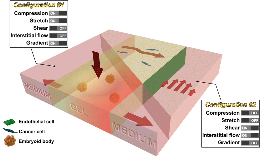 | ||
| Fig. 3 Future intergrated microfluidic system that allows the study of multiple mechanical stimuli on multiple cell types. For example, a microfluidic device can be used to study the effect of compression, stretch, and chemical gradient on embryoid bodies seeded in the collagen gel (configuration #1). In addition, a microlfuidic device can be used to study the effect of shear stress and interstitial flow on cancer cells (seeded in collagen gel) in the vicinity of endothelial cells (seeded as a monolayer in the channel) (configuration #2). | ||
Finally, while the addition of new functionalities or combinations of existing ones is needed, this should be done with an eye toward ease of use by the broader community. The value of these systems will be optimally enhanced if the assays can be incorporated into the numerous labs that study mechanobiology. For some, the technology is intimidating, and added capabilities are not required for many of the fundamental studies that are needed.
Acknowledgements
Funding from The National Cancer Institute (R21CA140096), the National Science Foundation Science and Technology Center for Emergent Behaviors of Integrated Cellular Systems (CBET-0939511), and Janssen Pharmaceuticals, Inc. is greatly appreciated. W. J. P. and R. L. are supported by National Science Foundation Graduate Research Fellowships. The authors would like to thank the members of the Kamm Lab for the helpful discussion and Serge Roux for the valuable suggestions in figure design.References
- Y. Xia and G. Whitesides, Annu. Rev. Mater. Sci., 1998, 28, 153–84 CrossRef CAS.
- S. W. Moore, P. Roca-Cusachs and M. P. Sheetz, Dev. Cell, 2010, 19, 194–206 CrossRef CAS.
- D. Wirtz, K. Konstantopoulos and P. C. Searson, Nat. Rev. Cancer, 2011, 11, 512–22 CrossRef CAS.
- G. Bao and S. Suresh, Nat. Mater., 2003, 2, 715–25 CrossRef CAS.
- F. Kurth, K. Eyer, A. Franco-Obregón and P. S. Dittrich, Curr. Opin. Chem. Biol., 2012, 1–9 Search PubMed.
- Kshitiz, D.-H. Kim, D. J. Beebe and A. Levchenko, Trends Biotechnol., 2011, 29, 399–408 CrossRef CAS.
- D. Huh, G. A. Hamilton and D. E. Ingber, Trends Cell Biol., 2011, 21, 745–54 CrossRef CAS.
- Y. Zheng and Y. Sun, Micro Nano Lett., 2011, 6, 327 CAS.
- S. a. Vanapalli, M. H. G. Duits and F. Mugele, Biomicrofluidics, 2009, 3, 12006 CrossRef.
- H. W. Hou, W. C. Lee, M. C. Leong, S. Sonam, S. R. K. Vedula and C. T. Lim, Cell. Mol. Bioeng., 2011, 4, 591–602 CrossRef.
- D.-H. Kim, P. K. Wong, J. Park, A. Levchenko and Y. Sun, Annu. Rev. Biomed. Eng., 2009, 11, 203–33 CrossRef CAS.
- C. F. Dewey, S. R. Bussolari, M. A. Gimbrone and P. F. Davies, J. Biomech. Eng., 1981, 103, 177–85 CrossRef.
- Y.-S. J. Li, J. H. Haga and S. Chien, J. Biomech., 2005, 38, 1949–1971 CrossRef.
- B. L. Gray, D. K. Lieu, S. D. Collins, R. L. Smith and A. I. Barakat, 2002, 9–16.
- J. W. Song, W. Gu, N. Futai, K. A. Warner, J. E. Nor and S. Takayama, Anal. Chem., 2005, 77, 3993–3999 CrossRef CAS.
- L. Chau, M. Doran and J. Cooper-White, Lab Chip, 2009, 9, 1897–1902 RSC.
- A. D. van der Meer, A. A. Poot, J. Feijen and I. Vermes, Biomicrofluidics, 2010, 4, 11103 CrossRef CAS.
- J. Wang, J. Heo and S. Z. Hua, Lab Chip, 2010, 10, 235–239 RSC.
- M. Rossi, R. Lindken, B. P. Hierck and J. Westerweel, Lab Chip, 2009, 9, 1403–1411 RSC.
- R. Estrada, G. A. Giridharan, M.-D. Nguyen, S. D. Prabhu and P. Sethu, Biomicrofluidics, 2011, 5, 32006–3200611 CrossRef.
- L. K. Chin, J. Q. Yu, Y. Fu, T. Yu, A. Q. Liu and K. Q. Luo, Lab Chip, 2011, 11, 1856–1863 RSC.
- G. M. Price, K. H. K. Wong, J. G. Truslow, A. D. Leung, C. Acharya and J. Tien, Biomaterials, 2010, 31, 6182–9 CrossRef CAS.
- X. Lin and B. P. Helmke, Biophys. J., 2008, 95, 3066–3078 CrossRef CAS.
- X. Lin and B. P. Helmke, Cell. Mol. Bioeng., 2009, 2, 231–243 CrossRef CAS.
- A. M. Ross, Z. Jiang, M. Bastmeyer and J. Lahann, Small, 2012, 8, 336–55 CrossRef CAS.
- Y. Yang, K. Kulangara, J. Sia, L. Wang and K. W. Leong, Lab Chip, 2011, 11, 1638–46 RSC.
- R. H. W. Lam, Y. Sun, W. Chen and J. Fu, Lab Chip, 2012, 12, 1865–1873 RSC.
- J. L. Tan, J. Tien, D. M. Pirone, D. S. Gray, K. Bhadriraju and C. S. Chen, Proc. Natl. Acad. Sci. U. S. A., 2003, 100, 1484–9 CrossRef CAS.
- M. A. Swartz and M. E. Fleury, Annu. Rev. Biomed. Eng., 2007, 9, 229–256 CrossRef CAS.
- J. W. Song and L. L. Munn, Proc. Natl. Acad. Sci. U. S. A., 2011, 108, 15342–15347 CrossRef CAS.
- V. Vickerman and R. D. Kamm, Integr. Biol., 2012, 4, 863–74 RSC.
- J. W. Song, J. Daubriac, J. M. Tse, D. Bazou and L. L. Munn, Lab Chip, 2012 Search PubMed.
- D. H. Ausprunk and J. Folkman, Microvasc. Res., 1977, 14, 53–65 CrossRef CAS.
- Y.-H. Hsu, M. L. Moya, P. Abiri, C. C. W. Hughes, S. C. George and A. P. Lee, Lab Chip, 2012 Search PubMed.
- J. Zhou and L. E. Niklason, Integr. Biol., 2012, 4, 1487–97 RSC.
- W. Zheng, B. Jiang, D. Wang, W. Zhang, Z. Wang and X. Jiang, Lab Chip, 2012, 12, 3441–3450 RSC.
- T. Herricks, K. B. Seydel, G. Turner, M. Molyneux, R. Heyderman, T. Taylor and P. K. Rathod, Lab Chip, 2011, 11, 2994–3000 RSC.
- J. W. Song, S. P. Cavnar, A. C. Walker, K. E. Luker, M. Gupta, Y.-C. Tung, G. D. Luker and S. Takayama, PLoS One, 2009, 4, e5756 Search PubMed.
- U. Y. Schaff, M. M. Q. Xing, K. K. Lin, N. Pan, N. L. Jeon and S. I. Simon, Lab Chip, 2007, 7, 448–456 RSC.
- E. Gutierrez, B. G. Petrich, S. J. Shattil, M. H. Ginsberg, A. Groisman and A. Kasirer-Friede, Lab Chip, 2008, 8, 1486–1495 RSC.
- M. J. Moehlenbrock, A. K. Price and R. S. Martin, Analyst, 2006, 131, 930–937 RSC.
- J. Wan, W. D. Ristenpart and H. A. Stone, Proc. Natl. Acad. Sci. U. S. A., 2008, 105, 16432–16437 CrossRef CAS.
- A. M. Forsyth, J. Wan, W. D. Ristenpart and H. A. Stone, Microvasc. Res., 2010, 80, 37–43 CrossRef CAS.
- B. Yap and R. D. Kamm, J. Appl. Physiol., 2005, 98, 1930–9 CrossRef.
- A. J. Engler, S. Sen, H. L. Sweeney and D. E. Discher, Cell, 2006, 126, 677–89 CrossRef CAS.
- L. A. Flanagan, Y.-E. Ju, B. Marg, M. Osterfield and P. A. Janmey, NeuroReport, 2002, 13, 2411–5 CrossRef.
- M. A. Hemphill, B. E. Dabiri, S. Gabriele, L. Kerscher, C. Franck, J. A. Goss, P. W. Alford and K. K. Parker, PLoS One, 2011, 6, e22899 CAS.
- S. Siechen, S. Yang, A. Chiba and T. Saif, Proc. Natl. Acad. Sci. U. S. A., 2009, 106, 12611–6 CrossRef CAS.
- H. G. Sundararaghavan, G. A. Monteiro, B. L. Firestein and D. I. Shreiber, Biotechnol. Bioeng., 2009, 102, 632–643 CrossRef CAS.
- B. S. Elkin, E. U. Azeloglu, K. D. Costa and B. Morrison, J. Neurotrauma, 2007, 24, 812–822 CrossRef.
- S. K. W. Dertinger, X. Jiang, Z. Li, V. N. Murthy and G. M. Whitesides, Proc. Natl. Acad. Sci. U. S. A., 2002, 99, 12542–12547 CrossRef CAS.
- L. J. Millet, M. E. Stewart, R. G. Nuzzo and M. U. Gillette, Lab Chip, 2010, 10, 1525–1535 RSC.
- A. M. Taylor, S. W. Rhee, C. H. Tu, D. H. Cribbs, C. W. Cotman and N. L. Jeon, Langmuir, 2003, 19, 1551–1556 CrossRef CAS.
- A. M. Taylor, M. Blurton-Jones, S. W. Rhee, D. H. Cribbs, C. W. Cotman and N. L. Jeon, Nat. Methods, 2005, 2, 599–605 CrossRef CAS.
- S. Hosmane, A. Fournier, R. Wright, L. Rajbhandari, R. Siddique, I. H. Yang, K. T. Ramesh, A. Venkatesan and N. Thakor, Lab Chip, 2011, 11, 3888–3895 RSC.
- M. H. Magdesian, F. S. Sanchez, M. Lopez, P. Thostrup, N. Durisic, W. Belkaid, D. Liazoghli, P. Grütter and D. R. Colman, Biophys. J., 2012, 103, 405–14 CrossRef CAS.
- A. N. Hellman, B. Vahidi, H. J. Kim, W. Mismar, O. Steward, N. L. Jeon and V. Venugopalan, Lab Chip, 2010, 10, 2083–92 RSC.
- Y. Yang, O. Gozen, A. Watkins, I. Lorenzini, A. Lepore, Y. Gao, S. Vidensky, J. Brennan, D. Poulsen, J. Won Park, N. Li Jeon, M. B. Robinson and J. D. Rothstein, Neuron, 2009, 61, 880–94 CrossRef CAS.
- H. J. Kim, J. W. Park, J. H. Byun, W. W. Poon, C. W. Cotman, C. C. Fowlkes and N. L. Jeon, ACS Chem. Neurosci., 2012, 3, 433–438 CrossRef CAS.
- K. Zhang, Y. Osakada, M. Vrljic, L. Chen, H. V Mudrakola and B. Cui, Lab Chip, 2010, 10, 2566–2573 RSC.
- S. Hosmane, I. H. Yang, A. Ruffin, N. Thakor and A. Venkatesan, Lab Chip, 2010, 10, 741–747 RSC.
- J.-M. Peyrin, B. Deleglise, L. Saias, M. Vignes, P. Gougis, S. Magnifico, S. Betuing, M. Pietri, J. Caboche, P. Vanhoutte, J.-L. Viovy and B. Brugg, Lab Chip, 2011, 11, 3663–3673 RSC.
- K. Rambani, J. Vukasinovic, A. Glezer and S. M. Potter, J. Neurosci. Methods, 2009, 180, 243–254 CrossRef.
- M. R. H. Hill and S. A. Greenfield, J. Neurosci. Methods, 2011, 195, 15–23 CrossRef CAS.
- Y. Huang, J. C. Williams and S. M. Johnson, Lab Chip, 2012, 12, 2103–2117 RSC.
- Z. Cai, J. Xin, D. M. Pollock and J. S. Pollock, Am. J. Physiol. Renal Physiol., 2000, 279, F270–F274 CAS.
- K.-J. Jang and K.-Y. Suh, Lab Chip, 2010, 10, 36–42 RSC.
- K. Jang, K. Sato, K. Igawa, U. Chung and T. Kitamori, Anal. Bioanal. Chem., 2008, 390, 825–32 CrossRef CAS.
- R. Baudoin, L. Griscom, M. Monge, C. Legallais and E. Leclerc, Biotechnol. Prog., 2007, 23, 1245–53 CAS.
- E. M. Frohlich, X. Zhang and J. L. Charest, Integr. Biol., 2012, 4, 75–83 RSC.
- D. Carney, J. DiRocco and G. Nieman, Crit. Care Med., 2005, 33, S122–S128 CrossRef.
- S. S. Kay, A. M. Bilek, K. C. Dee and D. P. Gaver, J. Appl. Physiol., 2004, 97, 269–76 CrossRef.
- D. Huh, H. Fujioka, Y.-C. Tung, N. Futai, R. Paine, J. B. Grotberg and S. Takayama, Proc. Natl. Acad. Sci. U. S. A., 2007, 104, 18886–91 CrossRef CAS.
- A. J. Banes, J. Gilbert, D. Taylor and O. Monbureau, J. Cell Sci., 1985, 75, 35–42 CAS.
- C. Moraes, J.-H. Chen, Y. Sun and C. A. Simmons, Lab Chip, 2010, 10, 227–34 RSC.
- K. Svennersten, M. Berggren, A. Richter-Dahlfors and E. W. H. Jager, Lab Chip, 2011, 11, 3287–93 RSC.
- N. J. Douville, P. Zamankhan, Y.-C. Tung, R. Li, B. L. Vaughan, C.-F. Tai, J. White, P. J. Christensen, J. B. Grotberg and S. Takayama, Lab Chip, 2011, 11, 609–19 RSC.
- D. Huh, B. D. Matthews, A. Mammoto, M. Montoya-Zavala, H. Y. Hsin and D. E. Ingber, Science, 2010, 328, 1662–8 CrossRef CAS.
- H. J. Kim, D. Huh, G. Hamilton and D. E. Ingber, Lab Chip, 2012, 12, 2165–74 RSC.
- J. H. Sung, J. Yu, D. Luo, M. L. Shuler and J. C. March, Lab Chip, 2011, 11, 389–92 RSC.
- S. Weinbaum, S. C. Cowin and Y. Zeng, J. Biomech., 1994, 27, 339–60 CrossRef CAS.
- E. Leclerc, B. David, L. Griscom, B. Lepioufle, T. Fujii, P. Layrolle and C. Legallaisa, Biomaterials, 2006, 27, 586–95 CrossRef CAS.
- S. Kou, L. Pan, D. van Noort, G. Meng, X. Wu, H. Sun, J. Xu and I. Lee, Biochem. Biophys. Res. Commun., 2011, 408, 350–5 CrossRef CAS.
- S. Akizuki, V. C. Mow, F. Müller, J. C. Pita, D. S. Howell and D. H. Manicourt, J. Orthop. Res., 1986, 4, 379–92 CrossRef CAS.
- P. G. Chao, Z. Tang, E. Angelini, A. C. West, K. D. Costa and C. T. Hung, J. Biomech., 2005, 38, 1273–81 CrossRef.
- P.-H. G. Chao, A. C. West and C. T. Hung, Am. J. Physiol.: Cell Physiol., 2006, 291, C718–25 CrossRef CAS.
- N. Nève, S. S. Kohles, S. R. Winn and D. C. Tretheway, Cell. Mol. Bioeng., 2010, 3, 213–228 CrossRef.
- S. Suresh, Acta Mater., 2007, 55, 3989–4014 CrossRef CAS.
- M. J. Bissell, D. C. Radisky, A. Rizki, V. M. Weaver and O. W. Petersen, Differentiation, 2002, 70, 537–546 CrossRef.
- M. J. Paszek, N. Zahir, K. R. Johnson, J. N. Lakins, G. I. Rozenberg, A. Gefen, C. A. Reinhart-King, S. S. Margulies, M. Dembo, D. Boettiger, D. A. Hammer and V. M. Weaver, Cancer Cell, 2005, 8, 241–254 CrossRef CAS.
- K. Funamoto, I. K. Zervantonakis, Y. Liu, C. J. Ochs, C. Kim and R. D. Kamm, Lab Chip, 2012, 1 Search PubMed.
- Y.-A. Chen, A. D. King, H.-C. Shih, C.-C. Peng, C.-Y. Wu, W.-H. Liao and Y.-C. Tung, Lab Chip, 2011, 11, 3626–33 RSC.
- N. L. Jeon, S. K. W. Dertinger, D. T. Chiu, I. S. Choi, A. D. Stroock and G. M. Whitesides, Langmuir, 2000, 16, 8311–8316 CrossRef CAS.
- W. Saadi, S. J. Wang, F. Lin and N. L. Jeon, Biomed. Microdevices, 2006, 8, 109–118 CrossRef.
- V. V Abhyankar, M. W. Toepke, C. L. Cortesio, M. a Lokuta, A. Huttenlocher and D. J. Beebe, Lab Chip, 2008, 8, 1507–15 RSC.
- W. K. Raja, B. Gligorijevic, J. Wyckoff, J. S. Condeelis and J. Castracane, Integr. Biol., 2010, 2, 696–706 RSC.
- B. J. Kim and M. Wu, Ann. Biomed. Eng., 2012, 40, 1316–27 CrossRef.
- E. T. Roussos, J. S. Condeelis and A. Patsialou, Nat. Rev. Cancer, 2011, 11, 573–587 CrossRef CAS.
- R. K. Jain and L. T. Baxter, Cancer Res., 1988, 7022–7032 CAS.
- T. Hompland, C. Ellingsen, K. M. Ovrebo and E. K. Rofstad, Cancer Res., 2012, 72, 4899–4908 CrossRef CAS.
- S. R. Chary and R. K. Jain, Proc. Natl. Acad. Sci. U. S. A., 1989, 86, 5385–5389 CrossRef CAS.
- J. D. Shields, M. E. Fleury, C. Yong, A. A. Tomei, G. J. Randolph and M. A. Swartz, Cancer Cell, 2007, 11, 526–538 CrossRef CAS.
- W. J. Polacheck, J. L. Charest and R. D. Kamm, Proc. Natl. Acad. Sci. U. S. A., 2011, 108, 11115–11120 CrossRef CAS.
- U. Haessler, J. C. M. Teo, D. Foretay, P. Renaud and M. A. Swartz, Integr. Biol., 2012, 4, 401–9 RSC.
- W. J. Polacheck, I. K. Zervantonakis and R. D. Kamm, Cell. Mol. Life Sci., 2012 Search PubMed.
- C. Gaggioli, S. Hooper, C. Hidalgo-Carcedo, R. Grosse, J. F. Marshall, K. Harrington and E. Sahai, Nat. Cell Biol., 2007, 9, 1392–1400 CrossRef CAS.
- D. Irimia and M. Toner, Integr. Biol., 2009, 1, 506–12 RSC.
- O. Ilina, G.-J. Bakker, A. Vasaturo, R. M. Hoffman and P. Friedl, Phys. Biol., 2011, 8, 029501–029501 CrossRef.
- W. C. Chang, L. P. Lee and D. Liepmann, Lab Chip, 2005, 5, 64–73 RSC.
- L. S. L. Cheung, X. Zheng, A. Stopa, J. C. Baygents, R. Guzman, J. a. Schroeder, R. L. Heimark and Y. Zohar, Lab Chip, 2009, 9, 1721–31 RSC.
- P. Rupprecht, L. Golé, J.-P. Rieu, C. Vézy, R. Ferrigno, H. C. Mertani and C. Rivière, Biomicrofluidics, 2012, 6, 14107–1410712 Search PubMed.
- F. L. Miles, F. L. Pruitt, K. L. van Golen and C. R. Cooper, Clin. Exp. Metastasis, 2008, 25, 305–24 CrossRef CAS.
- T. Das, T. K. Maiti and S. Chakraborty, Integr. Biol., 2011, 3, 684–95 RSC.
- A. J. Engler, M. A. Griffin, S. Sen, C. G. Bönnemann, H. L. Sweeney and D. E. Discher, J. Cell Biol., 2004, 166, 877–887 CrossRef CAS.
- X. Huang, N. Yang, V. F. Fiore, T. H. Barker, Y. Sun, S. W. Morris, Q. Ding, V. J. Thannickal and Y. Zhou, Am. J. Respir. Cell Mol. Biol., 2012, 47(3), 340–348 CrossRef CAS.
- J. S. Garanich, M. Pahakis and J. M. Tarbell, Am. J. Physiol.: Heart Circ. Physiol., 2005, 288, H2244–52 CrossRef CAS.
- Z. D. Shi, X. Y. Ji, H. Qazi and J. M. Tarbell, Am. J. Physiol.: Heart Circ. Physiol., 2009, 297, H1225–H1234 CrossRef CAS.
- V. F. Shimko and W. C. Claycomb, Tissue Eng. A, 2008, 14, 49–58 CrossRef CAS.
- S. Saha, L. Ji, J. J. de Pablo and S. P. Palecek, J. Cell. Physiol., 2006, 206, 126–137 CrossRef CAS.
- C. Wan, S. Chung and R. D. Kamm, Ann. Biomed. Eng., 2011, 39, 1840–1847 CrossRef.
- K. A. Beningo and Y.-L. Wang, Trends Cell Biol., 2002, 12, 79–84 CrossRef CAS.
- W. R. Legant, A. Pathak, M. T. Yang, V. S. Deshpande, R. M. McMeeking and C. S. Chen, Proc. Natl. Acad. Sci. U. S. A., 2009, 106, 10097–10102 CrossRef CAS.
- H. Vandenburgh, J. Shansky, F. Benesch-Lee, V. Barbata, J. Reid, L. Thorrez, R. Valentini and G. Crawford, Muscle Nerve, 2008, 37, 438–447 CrossRef CAS.
- T. Boudou, W. R. Legant, A. Mu, M. A. Borochin, N. Thavandiran, M. Radisic, P. W. Zandstra, J. A. Epstein, K. B. Margulies and C. S. Chen, Tissue Eng. A, 2012, 18, 910–919 CrossRef CAS.
- M. S. Sakar, D. M. Neal, T. Boudou, M. a. Borochin, Y. Li, R. Weiss, R. Kamm, C. S. Chen and H. H. Asada, Lab Chip, 2012, 12(23), 4976–4985 RSC.
- M. Pilarek, P. Neubauer and U. Marx, Sens. Actuators, B, 2011, 156, 517–526 CrossRef CAS.
- Y. Tanaka, K. Morishima, T. Shimizu, A. Kikuchi, M. Yamato, T. Okano and T. Kitamori, Lab Chip, 2006, 6, 362–368 RSC.
- J. Park, I. C. Kim, J. Baek, M. Cha, J. Kim, S. Park, J. Lee and B. Kim, Lab Chip, 2007, 7, 1367–1370 RSC.
- Y. Tanaka, K. Sato, T. Shimizu, M. Yamato, T. Okano and T. Kitamori, Lab Chip, 2007, 7, 207–212 RSC.
- S. Han, K. Yang, Y. Shin, J. S. Lee, R. D. Kamm, S. Chung and S.-W. Cho, Lab Chip, 2012, 12, 2305–8 RSC.
- C.-M. Chang, L.-F. Chiu, P.-W. Wang, D.-B. Shieh and G.-B. Lee, Lab Chip, 2011, 11, 2693–700 RSC.
- K. Eyer, S. Stratz, P. Kuhn, S. K. Küster and P. S. Dittrich, Anal. Chem., 2013 DOI:10.1021/ac303628j.
Footnote |
| † These authors contributed equally to this work. |
| This journal is © The Royal Society of Chemistry 2013 |