 Open Access Article
Catalytic cleavage of lignin β-O-4 link mimics using copper on alumina and magnesia–alumina†
Zea
Strassberger
,
Albert H.
Alberts
,
Manuel J.
Louwerse
,
Stefania
Tanase
* and
Gadi
Rothenberg
*
Van't Hoff Institute for Molecular Sciences, University of Amsterdam, Science Park 904, 1098 XH Amsterdam, The Netherlands. E-mail: s.grecea@uva.nl; g.rothenberg@uva.nl; Web: http://hims.uva.nl/hcsc Fax: +31 20 525 560
First published on 1st February 2013
Abstract
Copper on γ-alumina and on mixed magnesia–alumina, Cu/MgO–Al2O3, catalyse the hydrodeoxygenation (HDO) of β-O-4 lignin-type dimers, giving valuable aromatics. The typical selectivity to phenol is as high as 20%. By changing the support's acidity we can modify the dispersion of copper. Interestingly, more HDO occurs with larger copper agglomerates than with finely dispersed particles. The presence of copper also increases the selectivity of the HDO cleavage. Three different pathways are hypothesized for the reaction on the catalyst surface. Thus, copper activates ketones more and especially more selective towards cleavage than their corresponding alcohols. DFT calculations of bond dissociation energies correlate well with this experimental observation. Excitingly, ethylbenzene is formed in proportional amounts to phenol, showing that these catalysts can reduce the oxygen content of lignin-type product streams. Considering its low price and ready availability, we conclude that copper on alumina is a promising alternative catalyst for lignin depolymerization.
Introduction
Woody biomass holds the key for reducing our dependency on fossil carbon sources.1,2 The majority of nonfood-derived biomass is lignocellulose, a giant matrix of hemicellulose, cellulose and lignin. Currently, two approaches are used for converting this into liquid fuels and bulk chemicals: acid-catalyzed treatment and high-temperature pyrolysis/gasification.3–5 But both of these routes share the same problem: the breaking down of the valuable functional groups in lignin and cellulose. Since 2000, several methods have been published regarding transforming cellulose to more valuable chemicals such as glucose, sorbitol and HMF.6–8 However, there is still no viable process for converting lignin into chemicals, even though some industrial sectors produce massive amounts of lignin as a by-product.9 The pulp and paper industry, for example, produced in 2008 over 40 million tons of lignin, 95% of which was simply burned to generate energy.10Burning lignin is wasteful, because it is the most abundant natural resource of aromatic compounds. Fig. 1 shows a typical lignin fragment. Phenylpropane monomers have been identified as the major units of typical lignin (it is a random biopolymer), linked together through C–O bonds of α- and β-arylalkyl ethers.11,12 The β-O-4 linkages (highlighted dashed frames in Fig. 1) account for roughly 50% of all the linkages in lignin.13,14 Cleaving them selectively would give smaller fragments, while preserving the aromatic groups.
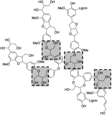 | ||
| Fig. 1 A typical lignin fragment (lignin is a random biopolymer) showing four β-O-4 linkages highlighted by dashed rectangles. | ||
Our aim, thus, is finding a selective catalytic alternative for converting lignin into high-value aromatics. The challenge is not so much in depolymerising lignin, but rather in finding a catalyst that will selectively cleave the β-O-4 linkages while preserving the aromaticity. Here we will show that Cu/γ-Al2O3 can do this job.
Results and discussion
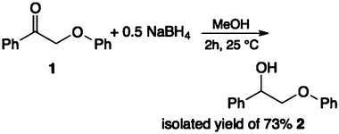
To start with, we selected appropriate β-O-4 linkage analogues. These must be similar enough to the real lignin so that the results are relevant, yet still simple enough for carrying out meaningful experiments on laboratory scale. While previous research focused on small monomers and alcohol–ether-type dimers,15–17 we opted for ketone–ether dimers, which are also important products of lignin depolymerisation.18,19 Thus, we selected 2-phenoxy-1-phenylethanone 1 and 2-phenoxy-1-phenylethanol 2.20 These were synthesized following the procedure of Britt et al. (eqn (1) and (2)).21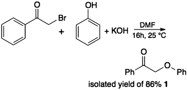 | (1) |
 | (2) |
For catalysts, we focused on copper and copper oxides supported on γ-Al2O3 and MgO–Al2O3. Apart from their economic and environmental advantages over heavy/noble metals,22 copper catalysts were also reported for hydro-deoxygenation reactions.23–25 Allegrini et al.26 showed the potential of reductive deoxygenation using copper on different supports, where aromatic ketones were fully deoxygenated to their methylene analogues. More recently, Sittisa et al.27,28 reported that surface copper interacts preferentially with carbonyl groups rather than with aromatic rings. This was explained in terms of the preferred adsorption mode on Cu, η1(O)-carbonyl, and the relatively weak interaction of copper with carbon–carbon double bonds.27 Therefore, we reasoned that copper sites might help to retain the aromaticity of our products.
As supports, we used the acidic/basic combination of magnesia–alumina, details of which are published elsewhere,29 and pure γ-alumina. We thus synthesised CuO/γ-Al2O3 and CuO/MgO–Al2O3.
The X-ray diffraction patterns of Cu/γ-Al2O3 and CuO/γ-Al2O3 show broad peaks for the alumina, indicating small crystallites. However, the copper peaks are very sharp, so the clusters are rather large (Fig. 2). These reflect the formation and agglomeration of crystalline Cu and CuO.30 Conversely, the XRD patterns of Cu/MgO–Al2O3 reveal much more dispersed copper particles, showing broad Cu(0) and CuO peaks. Note that Feng et al. reported that the presence of MgO can lead to a wider dispersion of the metal on the surface of the support.31,32
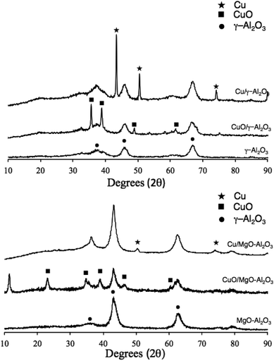 | ||
| Fig. 2 X-ray diffraction patterns of CuO/γ-Al2O3 and Cu/γ-Al2O3 (top) and CuO/MgO–Al2O3 and Cu/MgO–Al2O3 (bottom). | ||
Using TPR data (see Fig. 3) to approximate the reduced metal content by measuring the hydrogen consumption, we calculated that there was 10.6 wt% of copper on the alumina and 10.4 wt% of copper on the mixed support, magnesia–alumina. Nonetheless, comparing the two graphs shows two main differences: the peak shape and the temperature of reduction. For alumina we can identify two distinguished peaks and a temperature of reduction ranging from 230 to 250 °C. This corresponds to the reduction of Cu(II). The first peak is assigned to CuO clusters, whilst the second one is due to dispersed CuO particles on the γ-Al2O3 surface.33
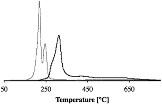 | ||
| Fig. 3 Temperature programmed reduction (TPR) plots for CuO/γ-Al2O3 (gray line) and CuO/MgO–Al2O3 (black line) using hydrogen as a reducing agent. | ||
In the case of Cu/MgO–Al2O3, the XRD pattern showed finely dispersed copper particles but the reduction temperature was higher than for CuO/γ-Al2O3 (see Fig. 3). This indicates a stronger interaction between copper oxide and the MgO–Al2O3 support, making the CuO particles less accessible for reduction. This is in line with the temperature needed for calcination: 500 °C (2 °C min−1) for 4 h.34
 | (3) |
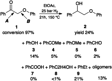
In a typical reaction (eqn (3)), a solution of 2-phenoxy-1-phenylethanone 1 or 2-phenoxy-1-phenylethanol 2 in ethyl acetate was stirred under 25 bar of H2 at 150 °C in a stainless steel autoclave with 2 wt% catalyst without prior reduction of the catalyst (see the detailed procedure in the Experimental section). To also investigate the role of Cu(0), the catalyst was pre-reduced in H2 for 2 h at 300 °C (the reduction temperature was selected from TPR experiments, see Fig. 3). Reaction progress was monitored by GC. Note that obtaining a quantitative mass balance in HDO reactions is particularly difficult.16 Here we succeeded in quantifying typically 85–95% with careful calibration and rigorous low-temperature quenching of the reaction mixture.
The main products were monoaromatics, (see Tables 2 and 3) plus typically 3–18% of oligomers. When using the ketone 1, we also observed a significant amount of reduction to the alcohol 2. Using Cu/γ-Al2O3 and Cu/MgO–Al2O3 gives phenol and ethylbenzene as the main monoaromatic products. This indicates that the cleavage occurs mostly at the C–O–aryl bond (pathway B) and that HDO is the main reaction route. Introducing basic sites on the support hinders HDO (the selectivity to ethylbenzene drops considerably; see for example the last two entries in Tables 2 and 3).
Interestingly, the alcohol 2 is less reactive than its ketone analogue. Other studies on several β-O-4 models reported a reduction of the bond dissociation energy (BDE) for oxidized species compared to their alcohol analogues.35,36 We calculated BDEs with DFT for our reactants as well, showing that indeed the ether bond is weaker in the ketone than in the alcohol (Table 1). As BDEs only explain thermal non-catalytic cleavage, we also studied the cleavage of protonated molecules (the cleavage is catalysed by alumina, the activity of which is usually explained by its acidity). However, these calculations were severely hindered by reorganisation of bonds, and therefore no numbers are reported here. Nevertheless, we do observe that both for the ketone and the alcohol the ether bond (pathway B) is activated by protonation of the ether. In the case of the alcohol, though, an immediate reorganisation occurs resulting in oligomerisation rather than cleavage. This fits strikingly well with the oligomerisation observed experimentally.
| Reactant | Pathway | BDE |
|---|---|---|

|
A | 265 |
| B | 253 | |

|
A | 284 |
| B | 201 |
A side effect increasing the difference in reactivity between the alcohol and ketone may be the three-dimensional shape of the molecules. Modelling the ketone and the corresponding alcohol in the gas phase, we see that the ketone is planar, which allows both oxygens to adsorb simultaneously. The alcohol, however, is twisted (see Fig. 4) making adsorption more difficult. Constraining the alcohol into a planar shape costs 12 kJ mol−1.
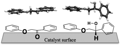 | ||
| Fig. 4 DFT-optimised 3D structures of the ketone 1 (top left) and the alcohol 2 (top right) and a possible approach of these to the catalyst surface (bottom). | ||
Nichols et al.37 reported the oxidation of the alcohol dimer 2 to the ketone dimer 1via a well-known Ru-dehydrogenative equilibrium. Under our conditions (substrate 2 and 25 bar of hydrogen pressure), this equilibrium is not observed, as neither dimer 1 nor acetophenone 4 were detected by GC analysis. To rule out the influence of the thermal cleavage in the absence of hydrogen, we ran a series of control experiments with argon pressure. These reactions gave less than 5% conversion. The main products were high-molecular-weight oligomers, with no oxidation of dimer 2 to dimer 1. Thus, at 150 °C an external hydrogen source is required to cleave the β-O-4 linkage via hydrogenolysis.
A series of blank experiments starting from 1, both in the absence of any catalyst and with only the oxide support (but no copper), showed no traces of the alcohol 2. This affirms that the reduction of 1 to 2 requires the copper active site.
For both 1 and 2, we envisage a two-step process. To illustrate this hypothesis, we propose the following mechanism for dimer 1 (Scheme 1). Alumina-catalysed hydrogenolysis of the dimer's C–O(aryl) bond (pathway B) occurs first, giving acetophenone and phenol. This is followed by copper-catalysed hydrodeoxygenation of the carbonyl group to the corresponding ethylbenzene. The presence of benzaldehyde and anisole can be explained by the hydrogenolysis of the OC–CH2O(aryl) bond (pathway A). Then, benzaldehyde is rapidly oxidized by air to benzoic acid (the latter is indeed absent under inert conditions, confirming that oxygen is needed38). If both bonds A and B are cleaved, methane may form. When Cu or CuO is present, for dimer 1 the hydrogenation of the ketone can occur as a third pathway. Dimer 2 can also split under influence of the alumina, but this only leads to oligomerisation. When metallic copper is present, dimer 2 can be split into phenol and 8, explaining the smaller amount of dimer 2 in the product mixture when starting from 1 and using the Cu/Al2O3 catalyst.
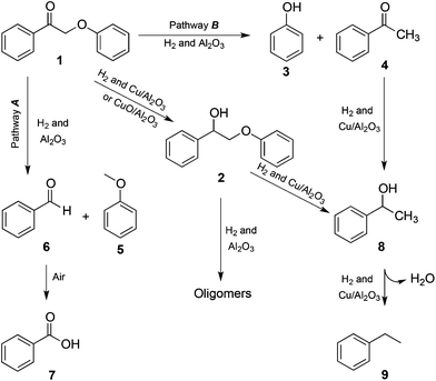 | ||
| Scheme 1 Reaction pathways for the β-O-4 cleavage of dimer 1. | ||
Excitingly, up to 22% yield of ethyl benzene was identified using a reduced copper catalyst and removing air/oxygen from the reaction mixture (see the experimental procedure for both 1 and 2). This is in agreement with the two-step route outlined above. The experiments gave roughly proportionate yields of phenol and ethylbenzene for both 1 and 2. Looking at the XRD pattern, we conclude that HDO occurs more readily with larger copper agglomerates than on finely dispersed sites.30 The highest selectivity towards phenol and ethylbenzene is obtained using plain alumina as a support, which also has the largest copper clusters. In contrast, when we used unreduced catalysts, copper is involved mainly in the reduction of 1 to 2, with only traces of HDO. In the absence of HDO, some phenol is still formed by the first reaction step, hydrogenolysis of the C–O aryl bond B. In this case, products 4, 5 and 7 are formed in higher amounts.
To understand the stability of our catalyst, we performed a series of recycling and leaching tests with the unreduced catalyst. These were run with the unreduced samples for practical reasons, but we expect similar results with reduced ones. The conversion remains constant after filtering the catalyst out, showing that the catalyst does not leach into solution. However, in the recycling experiments the conversion dropped to 44% after the first cycle, indicating catalyst deactivation. Twigg and Spencer39 studied the deactivation of supported copper metal catalysts for different hydrogenation reactions. They highlighted four main causes: (i) coke formation, (ii) sintering of copper particle, (iii) change of oxidation of copper and (iv) finally catalyst poisoning (with chlorine or sulfur compounds or adsorbed byproducts/products on the catalyst). Under our reaction conditions, poisoning of the catalyst with sulfur or chlorine is unlikely. Because we have organic hydrogenation reactions, coking is more likely. The reaction temperatures are too low to involve sintering. Rao et al.40 studied the deactivation of several copper catalysts in the hydrogenation of aromatic ketones and aldehydes. They reported that the catalyst deactivation occurs via different pathways: coke formation and/or poisoning of the catalyst (byproduct adsorption), or a change in the oxidation state of the copper during the reaction. Considering the close chemical similarity with our reaction products, similar deactivation processes may occur in the conversion of 1 and 2.
Conclusion
Copper particles supported on γ-alumina catalyse the scission of lignin-type β-O-4 linkages under HDO conditions, yielding phenol and ethylbenzene in substantial amounts. Using magnesia–alumina as the support increases the dispersion of copper, yet lowers the selectivity towards HDO. For industrial applications, the catalyst price/performance ratio is the key criterion, and the main challenge in this case is catalyst stability. Working with real lignin depolymerisation feeds means dealing with sulphur in the feedstock, as well as rapid deactivation by coke formation and potential poisoning by water. Importantly, our supported copper catalysts are cheap and readily available. As such, they open a practical route for decreasing the oxygenated content of lignin depolymerisation streams while keeping the aromatic rings intact, a key hurdle for efficient biomass conversion.41Experimental section
Materials, instrumentation and computational methods
Unless otherwise noted, all chemicals were purchased from commercial sources and used as received. The MgO–Al2O3 was a gift sample from Eurosupport.42X-Ray diffraction (XRD) patterns were obtained with a MiniFlex II diffractometer using Ni-filtered CuKα radiation. The X-ray tube was operated at 30 kV and 15 mA. Temperature programmed reduction (TPR) was carried out using hydrogen on an instrument equipped with a thermal conductivity detector (TCD). The H2-TPR studies were carried out for all catalysts. Samples of ca. 100 mg were loaded into a quartz U-tube reactor and were pre-treated in N2 (40 ml min−1) at 473 K for 30 min. After cooling to ambient temperature, the gas stream was switched to 5% H2/N2 flowing at 40 ml min−1. The samples were heated at 10 K min−1 to 1000 K, during which the hydrogen consumption was determined quantitatively by TCD. Surface area measurements were performed by the BET method using N2 at 77 K on a Thermo Scientific Surfer instrument. The samples were dried in a vacuum (1 × 10⁻³ mbar) for 3 h at 200 °C prior to the measurement.
DFT calculations were performed with the ADF package,43 using the rPBE functional44 and a DZP basis set. Calculations were done on isolated molecules. BDEs were calculated by comparing the energies of the starting molecules and the isolated radicals formed. For the protonated species, linear transits were performed, slowly breaking the bonds instead of comparing only the end energy. In this manner, the calculations allow for the possibility of oligomerisation.
Gas chromatography analyses were run on an Interscience GC-8000 gas chromatograph with 14% cyanopropylphenyl and 86% dimethyl polysiloxane capillary column (Rtx-1701, 30 m; 25 mm ID; 1 μm df). Samples were diluted in 1 ml MeOH. GC conditions: isotherm at 50 °C (2 min); ramp at 2 °C min−1 to 70 °C; ramp at 70 °C min−1 to 140 °C; ramp at 10 °C min−1 to 280 °C; isotherm at 260 °C (2 min). Products were identified by comparing their retention times to those of authentic samples.
Procedure for catalyst synthesis
Example:10 wt% CuO/γ-Al2O3. 1.0 g of γ-Al2O3 was added to a sol. of Cu(NO3)2·6H2O (0.38 g, 1.6 mmol) in 20 ml water and stirred for 2 h at 25 °C. The liquid was evaporated overnight on an oil bath at 60 °C, yielding a light green powder. This was dried at 120 °C for 24 h and then calcined in air at 500 °C (2 °C min−1) for 4 h. The analogous 10 wt% CuO/MgO–Al2O3 was prepared as above starting from 1.0 g of MgO–Al2O3. BET analysis data of all catalysts are given in the ESI.†Procedure for synthesising 2-phenoxy-1-phenylethanone 1
This is a modification of a previously published procedure.21,45 Bromoacetophenone (9.0 g, 45 mmol) and phenol (5.0 g, 53 mmol) were dissolved in 200 ml DMF, mixed with KOH (3.0 g, 53 mmol) and stirred overnight at room temperature. The product was then extracted with H2O and Et2O, dried over Na2SO4 and recrystallized from ethanol (yellowish powder, 86 mol% pure product yield based on bromoacetophenone). 1H NMR (DMSO) δ 5.58 (s, 2H), 6.93–6.98 (m, 3H), 7.27–7.31 (m, 2H), 7.56–7.60 (m, 2H), 7.68–7.72 (m, 1H), 8.02–8.04 (m, 2H), see ESI.†Procedure for synthesising 2-phenoxy-1-phenylethanol 2
This is a modification of a previously published procedure.21,45 A solution of 2-phenoxy-1-phenylethanone 1 (2.5 g, 11 mmol) in methanol (100 ml) was treated with small portions of sodium borohydride (5.5 mmol) and stirred for 2 h. A saturated solution of ammonium sulfate (200 ml) followed by CHCl3 (200 ml) was added to the reaction mixture. The organic layer was separated, washed with water (2 × 100 ml), dried and recrystallized from ethanol (fine white needles, 73 mol% pure compound yield based on 1). 1H NMR (DMSO) δ 4.01–4.02 (m, 2H), 4.90–4.94 (m, 1H), 5.63–5.64 (d, 1H), 6.90–6.94 (m, 3H), 7.25–7.47 (m, 7H), see ESI.†Procedure for catalytic hydrodeoxygenation (HDO)
Experiments were carried out in a six-parallel stainless steel 75 ml autoclave. In a typical experiment without an inert atmosphere and without pre-reducing the catalysts (results in Tables 2 and 3), 2 wt% of catalyst (copper weight relative to starting material) was added to a solution of 2-phenoxy-1-phenylethanone 1 (0.120 g, 0.56 mmol) in 10 ml of EtOAc. The autoclave was pressurized with 25 bar H2 and heated to 150 °C for 21 h. Then, the reactors were cooled down to room temperature using an ice bath. Liquid samples were analysed by GC using chlorobenzene as an external standard.| Catalyst | Reactant | Conv.% | Mass balance % | 2 | 3 | 4 | 5 | 6 | 7 | 8 | 9 | Oligomers |
|---|---|---|---|---|---|---|---|---|---|---|---|---|
| Yielda % | ||||||||||||
| a Yields determined by GC analysis (chlorobenzene is the external standard). b Standard reaction conditions: 0.120 mg reactant 1 in 10 mL EtOAc; 25 bar H2; 150 °C; 21 h, 2 wt% catalyst (amount of copper relative to 1) and with a minimal TON of 48–50. Catalyst was used without prior reduction and no inert conditions during reaction process. c Standard reaction conditions: 0.120 mg reactant 1 in 10 mL EtOAc; 25 bar H2; 150 °C; 21 h, 2 wt% catalyst (amount of copper relative to 1) and with a minimal TON of 42–48. Prior to the experiments, all catalysts were reduced at 300 °C under a flow of H2 for 2 h, the solvent was purged for 2 h with N2 and autoclaves were purged thrice. | ||||||||||||
| No catalyst |

|
4.71 | 95.3 | 0.0 | 3.3 | 0.0 | 0.0 | 0.0 | 0.0 | 0.0 | 0.0 | 0.9 |
| γ-Al2O3 | 38.7 | 91.4 | 0.0 | 18.8 | 0.5 | 0.4 | 1.2 | 6.6 | 0.0 | 0.0 | 7.8 | |
| MgO–Al2O3 | 30.0 | 89.0 | 0.0 | 12.2 | 0.6 | 0.6 | 4.3 | 2.6 | 0.0 | 0.0 | 5.6 | |
CuO/γ-Al2O3![[thin space (1/6-em)]](https://www.rsc.org/images/entities/char_2009.gif) b b |
96.7 | 88.1 | 45.2 | 17.3 | 1.8 | 0.7 | 1.9 | 9.1 | 2.2 | 0.0 | 6.1 | |
CuO/MgO–Al2O3![[thin space (1/6-em)]](https://www.rsc.org/images/entities/char_2009.gif) b b |
99.1 | 94.4 | 50.3 | 9.5 | 5.6 | 0.5 | 0.0 | 8.5 | 0.6 | 0.0 | 18.1 | |
Cu/γ-Al2O3![[thin space (1/6-em)]](https://www.rsc.org/images/entities/char_2009.gif) c c |
97.7 | 81.5 | 24.5 | 14.1 | 5.1 | 0.0 | 0.0 | 0.0 | 0.6 | 21.9 | 13.6 | |
Cu/MgO–Al2O3![[thin space (1/6-em)]](https://www.rsc.org/images/entities/char_2009.gif) c c |
82.3 | 87.5 | 34.4 | 10.2 | 1.6 | 0.1 | 4.3 | 0.0 | 4.3 | 5.3 | 16.3 | |
| Catalyst | Reactant | Conv. % | Mass balance % | 3 | 5 | 8 | 9 | Oligomers |
|---|---|---|---|---|---|---|---|---|
| Yielda % | ||||||||
| a Yields determined by GC analysis (chlorobenzene is the external standard). b Standard reaction conditions: 0.120 mg reactant 2 in 10 mL EtOAc; 25 bar H2; 150 °C; 21 h, 2 wt% catalyst (amount of copper relative to 2) and with a minimal TON of 8–10. Catalyst was used without prior reduction and no inert conditions during reaction process. c Standard reaction conditions: 0.120 mg reactant 2 in 10 mL EtOAc; 25 bar H2; 150 °C; 21 h, 2 wt% catalyst (amount of copper relative to 2) and with a minimal TON of 23–26. Prior to the experiments, all catalysts were reduced at 300 °C under a flow of H2 for 2 h, the solvent was purged for 2 h with N2 and autoclaves were purged thrice. | ||||||||
| No catalyst | <2 | 98.0 | <1 | 0.0 | 0.0 | 0.0 | <1 | |
| γ-Al2O3 |

|
25.7 | 89.5 | 2.5 | 0.4 | 1.5 | 0.0 | 18.2 |
| MgO–Al2O3 | 23.4 | 94.8 | 5.0 | 0.4 | 3.9 | 0.0 | 11.8 | |
CuO/γ-Al2O3![[thin space (1/6-em)]](https://www.rsc.org/images/entities/char_2009.gif) b b |
16.8 | 95.6 | 3.6 | 0.4 | 9.7 | 2.4 | 8.7 | |
CuO/MgO–Al2O3![[thin space (1/6-em)]](https://www.rsc.org/images/entities/char_2009.gif) b b |
20.6 | 87.5 | 10.9 | 0.0 | 4.1 | 0.0 | 2.6 | |
Cu/γ-Al2O3![[thin space (1/6-em)]](https://www.rsc.org/images/entities/char_2009.gif) c c |
52.5 | 93.0 | 21.7 | 0.1 | 2.4 | 19.1 | 5.2 | |
Cu/MgO–Al2O3![[thin space (1/6-em)]](https://www.rsc.org/images/entities/char_2009.gif) c c |
47.0 | 95.0 | 24.7 | 0.1 | 1.3 | 8.3 | 9.1 | |
In a second set of experiments (results shown in Tables 2 and 3), we used inert purging and the catalysts were pre-reduced as follows: 1.0 g of catalyst was heated at 300 °C under a 40 ml min−1 H2 for 2 h. The solvent, EtOAc, was purged for 2 h with nitrogen. 2 wt% of catalyst (copper weight related to starting material) was added to an autoclave containing a solution of 2-phenoxy-1-phenylethanone 1 (0.120 g, 0.56 mmol) in 10 ml EtOAc. The autoclaves were flushed thrice with argon, then pressurized to 25 bar H2 and heated to 150 °C for 21 h. The reactors were cooled down to room temperature using an ice bath. Liquid samples were analysed by GC using chlorobenzene as an external standard.
Procedure for recycling and leaching tests
Recycling and leaching tests were carried out in a six-parallel stainless steel 75 ml autoclave.For the recycling test, 2 wt% of catalyst (copper weight relative to starting material using 10 wt% CuO/γ-Al2O3) was added to a solution of 2-phenoxy-1-phenylethanone 1 (0.240 g, 1.12 mmol) in 20 ml of EtOAc. The autoclave was pressurized with 25 bar H2 and heated to 150 °C for 21 h. Then, the reactors were cooled down to room temperature using an ice bath. The catalyst was filtered out and placed in a desiccator overnight. The recycled catalyst was then reused for an extra 21 h reaction using 2-phenoxy-1-phenylethanone 1 (0.120 g, 0.56 mmol) in 10 ml of EtOAc with 2 wt% of catalyst (copper weight relative to starting material). Liquid samples were analysed by GC using chlorobenzene as an external standard.
For the leaching test, the autoclave was pressurized with 25 bar H2 and heated to 150 °C for 3 h. Then, the reactors were cooled down to room temperature using an ice bath. The catalyst was filtered out and the reaction mixture (without catalyst) was charged again with 25 bar H2 and heated to 150 °C for 20 h. Liquid samples were analysed by GC using chlorobenzene as an external standard.
Acknowledgements
This research was performed within the framework of the CatchBio program. The authors gratefully acknowledge the support of the Smart Mix Program of the Netherlands, Ministry of Economic Affairs, and the Netherlands Ministry of Education, Culture and Science.Notes and references
- E. Dorrestijn, L. J. J. Laarhoven, I. W. C. E. Arends and P. Mulder, J. Anal. Appl. Pyrolysis, 2000, 54, 153–192 CrossRef CAS.
- A. Séguin, Curr. Opin. Environ. Sustainability, 2011, 3, 90–94 CrossRef.
- J. R. Regalbuto, Science, 2009, 325, 822–824 CrossRef.
- Z. Ma, E. Troussard and J. A. van Bokhoven, Appl. Catal., B., 2012, 423–424, 130–136 CAS.
- J. Zakzeski, P. C. A. Bruijnincx, A. L. Jongerius and B. M. Weckhuysen, Chem. Rev., 2010, 110, 3552–3599 CrossRef CAS.
- H. Lawford and J. Rousseau, Appl. Biochem. Biotechnol., 2002, 98–100, 429–448 CrossRef CAS.
- G. W. Huber, J. N. Chheda, C. J. Barrett and J. A. Dumesic, Science, 2005, 308, 1446–1450 CrossRef CAS.
- H. Kobayashi, Y. Ito, T. Komanoya, Y. Hosaka, P. L. Dhepe, K. Kasai, K. Hara and A. Fukuoka, Green Chem., 2011, 13, 326–333 RSC.
- R. J. A. Gosselink, E. de Jong, B. Guran and A. Abacherli, Ind. Crops Prod., 2004, 20, 121–129 CrossRef CAS.
- M. Kleinert and T. Barth, Chem. Eng. Technol., 2008, 31, 736–745 CrossRef CAS.
- J. Gierer, Wood Sci. Technol., 1980, 14, 241–266 CrossRef CAS.
- R. Vanholme, B. Demedts, K. Morreel, J. Ralph and W. Boerjan, Plant Physiol., 2010, 153, 895–905 CrossRef CAS.
- E. Adler, Wood Sci. Technol., 1977, 11, 169–218 CrossRef CAS.
- F. S. Chakar and A. J. Ragauskas, Ind. Crops Prod., 2004, 20, 131–141 CrossRef CAS.
- S. Jia, B. J. Cox, X. Guo, Z. C. Zhang and J. G. Ekerdt, Ind. Eng. Chem. Res., 2010, 50, 849–855 CrossRef.
- A. L. Jongerius, R. Jastrzebski, P. C. A. Bruijnincx and B. M. Weckhuysen, J. Catal., 2012, 285, 315–323 CrossRef CAS.
- H. Kawamoto, S. Horigoshi and S. Saka, J. Wood Sci., 2007, 53, 168–174 CrossRef CAS.
- R. J. A. Gosselink, W. Teunissen, J. E. G. van Dam, E. de Jong, G. Gellerstedt, E. L. Scott and J. P. M. Sanders, Bioresour. Technol., 2012, 106, 173–177 CrossRef CAS.
- K. Takeno, T. Yokoyama and Y. Matsumoto, BioResources, 2012, 7, 99–111 Search PubMed.
- T. vom Stein, T. Weigand, C. Merkens, J. Klankermayer and W. Leitner, ChemCatChem, 2013, 5, 439–441 CrossRef CAS.
- P. F. Britt, A. C. Buchanan, M. J. Cooney and D. R. Martineau, J. Org. Chem., 2000, 65, 1376–1389 CrossRef CAS.
- J. E. Tilton and G. Lagos, Resour. Policy, 2007, 32, 19–23 CrossRef.
- T. T. Pham, L. L. Lobban, D. E. Resasco and R. G. Mallinson, J. Catal., 2009, 266, 9–14 CrossRef CAS.
- M. V. Bykova, D. Y. Ermakov, V. V. Kaichev, O. A. Bulavchenko, A. A. Saraev, M. Y. Lebedev and V. A. Yakovlev, Appl. Catal., B, 2012, 113–114, 296–307 CrossRef CAS.
- V. Dundich, S. Khromova, D. Ermakov, M. Lebedev, V. Novopashina, V. Sister, A. Yakimchuk and V. Yakovlev, Kinet. Catal., 2010, 51, 704–709 CrossRef CAS.
- F. Zaccheria, N. Ravasio, M. Ercoli and P. Allegrini, Tetrahedron Lett., 2005, 46, 7743–7745 CrossRef CAS.
- S. Sitthisa and D. Resasco, Catal. Lett., 2011, 141, 784–791 CrossRef CAS.
- S. Sitthisa, T. Sooknoi, Y. Ma, P. B. Balbuena and D. E. Resasco, J. Catal., 2011, 277, 1–13 CrossRef CAS.
- Z. Strassberger, S. Tanase and G. Rothenberg, Eur. J. Org. Chem., 2011, 5246–5249 CrossRef CAS.
- P. W. Park and J. S. Ledford, Appl. Catal., B, 1998, 15, 221–231 CrossRef CAS.
- Z. Wang, H. Wan, B. Liu, X. Zhao, X. Li, H. Zhu, X. Xu, F. Ji, K. Sun, L. Dong and Y. Chen, J. Colloid Interface Sci., 2008, 320, 520–526 CrossRef CAS.
- J.-T. Feng, X.-Y. Ma, D. G. Evans and D.-Q. Li, Ind. Eng. Chem. Res., 2011, 50, 1947–1954 CrossRef CAS.
- W.-P. Dow, Y.-P. Wang and T.-J. Huang, Appl. Catal., A, 2000, 190, 25–34 CrossRef CAS.
- K. M. Lee and W. Y. Lee, Catal. Lett., 2002, 83, 65–70 CrossRef CAS.
- S. Kim, S. C. Chmely, M. R. Nimlos, Y. J. Bomble, T. D. Foust, R. S. Paton and G. T. Beckham, J. Phys. Chem. Lett., 2011, 2, 2846–2852 CrossRef CAS.
- A. Beste and A. C. Buchanan, J. Org. Chem., 2011, 76, 2195–2203 CrossRef CAS.
- J. M. Nichols, L. M. Bishop, R. G. Bergman and J. A. Ellman, J. Am. Chem. Soc., 2010, 132, 12554–12555 CrossRef CAS.
- J. R. Pound, J. Phys. Chem., 1930, 35, 1496–1497 CrossRef.
- M. V. Twigg and M. S. Spencer, Appl. Catal., A, 2001, 212, 161–174 CrossRef CAS.
- R. Rao, R. T. Baker and M. A. Vannice, Catal. Lett., 1999, 60, 51–57 CrossRef CAS.
- P. Gallezot, ChemSusChem, 2008, 1, 734–737 CrossRef CAS.
- http://www.eurosupport.nl/ .
- G. te Velde, F. M. Bickelhaupt, E. J. Baerends, C. Fonseca Guerra, S. J. A. van Gisbergen, J. G. Snijders and T. Ziegler, J. Comput. Chem., 2001, 22, 931–967 CrossRef CAS.
- B. Hammer, L. B. Hansen and J. K. Nørskov, Phys. Rev. B: Condens. Matter, 1999, 59, 7413–7421 CrossRef.
- P. H. Kandanarachchi, T. Autrey and J. A. Franz, J. Org. Chem., 2002, 67, 7937–7945 CrossRef CAS.
Footnote |
| † Electronic supplementary information (ESI) available: 1H NMR spectra of 1 and 2, and surface area measurements (BET) of both catalysts. See DOI: 10.1039/c3gc37056a |
| This journal is © The Royal Society of Chemistry 2013 |
