 Open Access Article
 This Open Access Article is licensed under a
 Creative Commons Attribution 3.0 Unported Licence
Low-temperature, solution-processed, layered V2O5 hydrate as the hole-transport layer for stable organic solar cells†
Gerardo Terán-Escobar,
Jonas Pampel,
José M. Caicedo and
Mónica Lira-Cantú*
Catalan Institute of Nanoscience and Nanotechnology (ICN2), Campus UAB, Building ICN2, Bellaterra, Barcelona, E-0193, Spain. Consejo Superior de Investigaciones Cientificas (CSIC), Campus UAB, Building ICN2, Bellaterra, Barcelona, E-0193, Spain. E-mail: monica.lira@cin2.es; Fax: +34 937373606; Tel: +34 937374615
First published on 4th September 2013
Abstract
Layered V2O5 hydrate has been applied as the hole transport layer (HTL) in organic solar cells (OSCs). V2O5 is obtained from a sodium metavanadate solution in water under ambient conditions, resulting in a final thin film of formula V2O5·0.5H2O. The 0.5 water molecules are not removed from the V2O5 layered structure unless the sample is heated above 250 °C, which makes the thin film highly stable under real working conditions. The HTL was used in OSCs in the normal and the inverted configurations, applying metallic Ag as the back-metal electrode in both cases. Fabrication of both OSC configurations completely by solution-processing printing methods in air is possible, since the Al electrode needed for the normal-configuration OSC is not required. The work function (WF) and band gap energy (BG) of the V2O5 thin films were assessed by XPS, UPS and optical analyses. Different WF values were observed for V2O5 prepared from a fresh V2O5–isopropanol (IPA) solution (5.15 eV) and that prepared from a 24 h-old solution (5.5 eV). This difference is due to the gradual reduction of vanadium (from V5+ to V4+) in IPA. The OSCs made with the V2O5 thin film obtained from the 24 h-old V2O5–IPA solution required photo-activation, whereas those made with the freshly obtained V2O5 did not. Outdoor stability analyses of sealed OSCs containing a V2O5 HTL in either configuration revealed high stability for both devices: the photovoltaic response at T80 was retained for more than 1000 h.
Broader contextOrganic Solar Cells (OSCs) have achieved an impressive increase in power conversion efficiency in the past few years, with values above the 12% range. Yet, in order to be competitive with existing energy sources from fossil fuels and modern inorganic photovoltaic technologies, OSCs must reduce fabrication costs and improve its energy payback time (EPBT). To achieve the latter, the fabrication of OSCs by large scale, solution processing methods applying inexpensive, low temperature techniques is required. An important aim is the exclusion of toxic organic solvents, being water-based or alcohol-based solutions is highly desired. In this work, a layered V2O5 hydrate has been applied as the hole transport layer in stable OSCs. V2O5 is obtained from the dissolution of sodium metavanadate in water under ambient atmospheric conditions, resulting in a final thin film with the V2O5·0.5H2O formula. OSCs with normal and inverted configuration applying metallic Ag as the back metal electrode in both cases have been fabricated. The use of a Ag electrode eliminates the need for a highly reactive work function metal electrodes (Al, Ca) for the normal configuration OSC, and permits the fabrication of both OSC configurations completely by solution processing printing methods in air. Outdoor stability analyses of sealed devices showed high stability, maintaining the photovoltaic response at T80 for more than 1000 h. |
1 Introduction
The predicted maximum power conversion efficiency (PCE) of organic solar cells (OSCs) has been empirically estimated to be 10 to 12%, but theoretical calculations suggest that values of 20 to 24% could be achieved, which are comparable to those of crystalline Si solar cells.1 However, OSCs must also be cost-competitive and show long lifetimes. The former requires inexpensive methods for large-scale fabrication, including solution-processing techniques such as roll-to-roll compatible printing techniques.2–8 Ideally, a single printing method would be used to continuously and rapidly process all layers; unfortunately, no such process exists yet and therefore, multiple techniques must be employed. Additionally, the envisaged mass-production of OSCs indicates that toxic organic solvents will have to be replaced with non-toxic, alcohol or water-based solutions and inks. Interestingly, a few cases of partial or complete roll-to-roll fabrication methods of OSCs with water-based inks have very recently been reported.5,9–11Transition metal oxides (TMOs) have been employed in organic solar cells, especially TiO2 and ZnO. Their most attractive feature is the possibility to be deposited by low temperature solution processing methods. Among them are also V2O5,12–21 NiO,22–30 MoO3,31–35 WO336–39 or Sb2O3.40 These TMOs exhibit a wide range of energy level alignments,41–44 good transparency as thin films, are easy to manipulate, and confer low-resistance ohmic contacts to the OSC.45 Moreover, TMOs can enhance the adhesion to the active layer8,16 and show higher stability to ambient atmosphere relative to PEDOT:PSS, which has been shown to be detrimental for OSCs due to its high hygroscopicity and its acidic pH.46–50 Additionally, the high power conversion efficiency requirement for future OSCs rely on small-molecule OSCs (SmOSCs)39,40,51,52 and multi-junction or tandem solar cell (TmOSC) structures, whose PCE values presently range from 10–12%.5,10,53–56 One interesting TMO is V2O5, which has been reported to be a good candidate for the HTL in OSCs. To date, V2O5 HTLs have been synthesised chiefly by multistep techniques. Examples include the suspension of V2O5 nanoparticulates obtained from the hydrolysis of vanadium(III) acetyl acetate19 or the fabrication of a bronze V2O5 HTL from a suspension of the metal oxide obtained after the reaction between the metal powder and H2O2.21 Among the most widespread fabrication methods is the application of sol–gels made from vanadium(V) oxytriisopropoxide (ViPr),5,14,15,57,58 which is a compound known for its high toxicity, reactivity and cost.
Herein we present the synthesis, optimisation and application of water-based, solution processable V2O5 as the HTL in OSCs. The HTL was fabricated at low temperature in air without the need for any high temperature post-deposition treatments or multistep reactions. The water-based layered V2O5 hydrate is highly compatible with the fabrication of OSCs by large-area, low-cost, fast processing and high-throughput printing,5,15 and also enables the preparation of ZnO/V2O5 recombination layers required for TmOSCs.59 We demonstrate here that the application of the low-temperature water-based V2O5 solution can be tuned in order to fabricate OSCs in either the inverted or the normal configurations, on either glass or flexible substrates. Moreover, we have fabricated OSCs with both configurations applying only Ag as the back metal electrode. Thus, our OSCs can be made completely by solution-processing methods, as they do not require an Al electrode for the normal-configuration OSCs10 and the Ag metal electrode can be deposited by established solution-processing printing techniques.11 A careful optimisation of the V2O5 hydrate solution permitted to obviate the requirement for photo-activation of the solar cell in air.19 Finally, the OSC devices also show good outdoor stability maintaining T80 for more than 1000 h.
2 Experimental section
2.1 Synthesis of TMOs
The TiO2 solution was fabricated and deposited as previously reported,60 and the ZnO nanoparticles were synthesised following the Pacholski method61 and deposited by spin coating at 1000 rpm. The V2O5 hydrate solution was obtained using an adapted version of Livage's method.62 Briefly, 4.5 g of sodium metavanadate (NaVO3) are dissolved in 100 mL of deionised water by heating the mixture at 90 °C with stirring. The resulting transparent solution is passed through a cation-exchange resin (DOWEX 2x-100, Aldrich) to obtain metavanadic acid (HVO3) as a yellow solution, which is stored in a closed glass flask under an ambient atmosphere. As the solution ages, it becomes yellowish-orange, indicating the presence of condensed species such as decavanadates ([V10O28]6−). Finally, the orange solution changes to dark red, which is characteristic of the V2O5 hydrate (gel). The condensation and aging of the solution occurs over ∼20 days, after which, the viscous hydrate solution stabilises and is ready to use. A bright red vanadium pentoxide V2O5·nH2O gel is obtained. For the inverted OSC a 1![[thin space (1/6-em)]](https://www.rsc.org/images/entities/char_2009.gif) :1 mixture of V2O5 hydrate (9 mg mL−1) in isopropanol (IPA) was spin-coated at 1000 rpm, and then annealed at 120 °C for 5 min. For the normal configuration OSCs the V2O5 solution was spin coated at 1000 rpm directly from the solution without the aid of the IPA.
:1 mixture of V2O5 hydrate (9 mg mL−1) in isopropanol (IPA) was spin-coated at 1000 rpm, and then annealed at 120 °C for 5 min. For the normal configuration OSCs the V2O5 solution was spin coated at 1000 rpm directly from the solution without the aid of the IPA.
2.2 Solar cell fabrication
The response of the solar cells was independent of the used substrate (ITO or FTO). All the flexible substrates were made on a PET/ITO transparent film. Substrates of FTO on glass were supplied by SOLEMS (resistance: 70 to 100 ohms). PET/ITO substrates were brought from Aldrich (resistance: 35 ohms). The substrates were cleaned with a water–soap solution, rinsed with deionised water, ultrasonicated in ethanol (99%), dried under N2 flux and finally, ozone treated in a UV-surface decontamination system (Novascan, PSD-UV) connected to an O2 supply. The OSCs were fabricated in either the normal configuration (FTO/V2O5/P3HT:PCBM/TiO2/Ag) or the inverted configuration (FTO/TiO2/P3HT:PCBM/V2O5/Ag). TiO2 was used on glass/FTO substrates and was replaced by ZnO in order to fabricate flexible OSCs on ITO/PET (Aldrich). The bulk heterojunction blend comprised a 1:0.8 mixture of regioregular P3HT (Merck, 98%) and PCBM (Solenne, 99.5%) that was dissolved in dichlorobenzene (Sigma-Aldrich). The blend was spin coated at 1000 rpm, affording a 200 to 250 nm-thick P3HT:PCBM film. The devices were subsequently annealed at 120 °C for 5 min in air. A 100 nm-thick Ag back metal electrode was deposited by thermal evaporation in an evaporation system (Auto 306, Broc Edwards) with a base pressure of 10−7 torr at a deposition rate of 1 Å s−1. The final active area was 0.2 cm2. The solar cells were sealed by applying a two-component adhesive (ThreeBond, 30Y-727 and 31x-167-2), which was mixed in a 1:1 ratio and cured under UV light for 10 min.
2.3 Characterisation
The thicknesses of the polymer layers were measured using a Nanopics-2100 from Nanopics profilometer and by SEM (Quanta FEI 200 FEG-ESEM). Optical measurements were performed using a UV-vis spectrophotometer (UV 1800, Shimadzu). Grazing incidence X-ray analyses were done using a Rigaku unit and measured between 5° and 80°. TGA analyses were done using an STA 449 F1 Jupier (Netzsch). Contact angles were analysed using a DSA 100 (KRUSS). XPS was done with the Al κα (1486.6 eV). All spectra were adjusted according to the value of the C 1s peak at 284.4 ± 0.1 eV. The UPS were obtained using a He lamp (He l 21.2 eV) at an experimental resolution of 0.15 eV. The samples were biased at −5 V.2.4 Photovoltaic characterisation
The solar simulation was performed on a KHS1200 (Steuernagel Solarkonstant) equipped with an AM1.5 filter for all characterisations (100 mW cm−2, AM1.5G, 72 °C). The equipment was calibrated according to the ASTM G173. IV-curves were measured using a Keithley 2601 multimeter. Light intensity was 100 W m−2 calibrated with a Zipp & Konen CM-4 pyranometer, which was used constantly during measurements to set light intensity, and a calibrated S1227-1010BQ photodiode from Hamamatsu was also applied for calibration before each measurement. IPCE analyses were done with a QE/IPCE measurement System from Oriel (from 300 to 700 nm; at 10 nm intervals). The results were not corrected for any intensity losses due to light absorption or reflection by the glass support.2.5 Outdoor stability analyses
The outdoor stability analyses were done following the ISOS-1 procedures63 at the Laboratory of Nanostructured Materials for Photovoltaic Energy of the Catalan Institute of Nanoscience and Nanotechnology (ICN2-CSIC), located in Barcelona, Spain (41.30° N 2.09° W), using a solar tracking positioning system. The system comprises a large dual axis-controlled platform with fully automated motors, which enables turning of the tracker hour angle up to 100° (which translates to nearly 7 hours of perpendicular solar tracking) and turning of the tracker elevation angle from 15° to 90° (which enables full tracking of solar elevation). We developed in-house software to control the photovoltaic response of sixteen solar cells at the same time and to continuously monitor light irradiation, temperature and relative humidity over time. IV-curves were measured using a 2602A dual-channel SMU multimeter and a 3700 series switch/multimeter (both from Keithley). PCE values were calculated using the maximum daily irradiance level. The light irradiation was measured with a Zipp&Konen CM-4 pyranometer. The temperature and relative humidity were monitored with a combined sensor (Theodor Friedrichs).3 Results and discussion
3.1 Optimisation of the V2O5 layer: concentration and layer thickness
V2O5 hydrate is obtained from an aqueous solution of sodium metavanadate (NaVO3). During synthesis, the NaVO3 dissolved in water is converted into metavanadic acid (HVO3) via cation-exchange. A condensation process over time results in the formation of decavanadates ([V10O28]6−), and finally, a dark red solution is obtained, corresponding to vanadium pentoxide hydrate (V2O5·nH2O, where n varies). The variable water molecules in V2O5 hydrate are partially eliminated when the V2O5·nH2O thin film is formed on the glass/FTO substrate. The number of water molecules (n) in the formula V2O5·nH2O ranges from 0 to 2.2, depending on the annealing temperature: below 120 °C, n = 1.6; from 120 to 250 °C, n = 0.5; from 250 to 320 °C, n = 0.1; and annealing above 320 °C promotes the total elimination of water (n = 0) and the crystallisation of V2O5 into its rhombic crystalline phase.64,65The V2O5 film used in this work was prepared by spin coating and the substrate was then treated at 120 °C for several minutes before being applied to the OSCs. The final formula of the thin film is V2O5·0.5H2O (the number of water molecules was calculated from the TGA analyses performed in air). Once the films have been prepared, the water molecules can only be removed if the film is heated above 250 °C. However, under real working conditions the OSCs will never reach those temperatures and therefore, the water in the V2O5 interlayer can be considered stable.
Fig. 1 shows the photovoltaic response of inverted organic solar cells with the glass/FTO/TiO2/PCM:P3HT/V2O5/Ag configuration, depending on the V2O5 concentration. For the fabrication of inverted devices, the deposition of V2O5 on top of the active P3HT:PCBM layer requires mixing of V2O5 hydrate with isopropanol (IPA) to improve adherence. The optimum ratio of V2O5 to IPA was found to be 1:1 (as determined by contact angle measurements; see ESI Fig. S1†). The solution obtained was then spin-coated at 1000 rpm in an ambient atmosphere, and finally, heated at 120 °C for 5 min. There is a clear improvement on the photovoltaic response of the device (ca. in FF, Jsc and PCE) when the concentration of the oxide is increased from 2 mg mL−1 to 9 mg mL−1, as observed in Fig. 1. The PCE and FF increase and ultimately stabilise at 3% and 50%, respectively. As the FF increased, the Jsc also stabilised at a V2O5 concentration of 9 mg mL−1. Increasing the photovoltaic response by increasing the concentration of V2O5 above these values was not achievable due its limited solubility. Thus, the optimal value chosen for fabrication of the inverted OSCs was 9 mg mL−1. An increase in the thin film layer thickness was also observed when raising the concentration of the oxide from 2 mg mL−1 to 9 mg mL−1, with values ranging from 60 nm to 125 nm (as measured by SEM and profilometry, Fig. 1e). The possibility to fabricate thick film layers without compromising the photovoltaic performance of the device (i.e. by increasing series resistance) has also been observed by Brabec et al.19 In our case, we attributed this response to the mixed ionic-electronic conductivity that characterises the V2O5·0.5H2O thin film. Finally, Fig. 1f shows the atomic force microscopy (AFM) image, at a 2 mm × 2 mm scan size, of the thin film V2O5 made with a solution concentration of 9 mg mL−1. A nanostructured surface with high surface roughness is observed for the thin film.
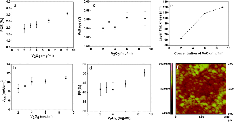 | ||
| Fig. 1 Optimisation of the concentration of the V2O5 hydrate solution used to create the hole transport layer in an inverted organic solar cell (glass/FTO/TiO2/P3HT:PCBM/V2O5/Ag). (a) PCE (%) and (b) Jsc (mA cm−2). Measurements made at 100 W cm−2 AM1.5G. (c) Voc and (d) FF (%), (e) layer thickness vs. V2O5 concentration and (f) AFM analyses of the V2O5 thin film made with a concentration of 9 mg mL−1. | ||
To compare the performance of our V2O5 HTLs with that of the most widely used HTL, PEDOT:PSS, we fabricated and assessed OSCs of both configurations. The devices were prepared on glass/FTO substrates (the fabrication of flexible OSCs applying the V2O5 HTL is also possible, see ESI Fig. S2†). Fig. 2 shows the IV curves and the IPCE spectra obtained for the devices. In all cases the ETL was ZnO. Table 1 shows the photovoltaic parameters obtained for the different OSCs; for comparison purposes, we have also included solar cells containing a TiO2 ETL. The reported values are mean values from six samples. The best photovoltaic performance (PCE: 3%) was generally observed for the OSC fabricated on glass/FTO substrates, with TiO2 as the ETL and V2O5 hydrate as the HTL. In this case, the OSCs employing the V2O5 hydrate resulted in better performance when compared to PEDOT:PSS. The OSCs with ZnO and V2O5 showed a very similar response with photovoltaic PCEs of ca. 2.5 to 2.6%. Our results indicate that a similar response can be achieved for OSCs with layered V2O5 hydrate when compared to the PEDOT:PPS HTL.
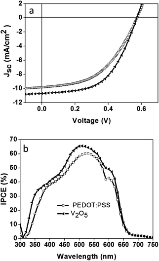 | ||
| Fig. 2 IV curves (a) and the corresponding IPCE spectra (b) for the inverted configuration organic solar cell in glass/FTO/ZnO/P3HT:PCBM/V2O5/Ag and, for comparison purposes, similar cells containing PEDOT:PSS instead of V2O5. Measurements were taken at 100 mW cm−2 AM1.5G. | ||
| Inverted configuration | Voc (V) | Jsc (mA cm−2) | FF (%) | PCE (%) |
|---|---|---|---|---|
| Glass/FTO/TiO2/P3HT:PCBM/PEDOT:PSS/Ag | 0.557 ± 0.015 | 9.84 ± 0.43 | 45.43 ± 2.74 | 2.53 ± 0.17 |
| Glass/FTO/TiO2/P3HT:PCBM/V2O5/Ag | 0.563 ± 0.015 | 10.69 ± 0.38 | 50.49 ± 1.90 | 3.09 ± 0.18 |
| Glass/FTO/ZnO/P3HT:PCBM/PEDOT:PSS/Ag | 0.543 ± 0.013 | 10.07 ± 0.37 | 45.06 ± 1.16 | 2.64 ± 0.12 |
| Glass/FTO/ZnO/P3HT:PCBM/V2O5/Ag | 0.540 ± 0.016 | 9.54 ± 1.10 | 47.20 ± 1.90 | 2.58 ± 0.22 |
3.2 S-shape curve and photo-annealing of the inverted OSC in air
Fig. 3 shows the IV-curves and IPCE spectra obtained for our OSCs fabricated with fresh (1) and 24 hour-old (2) V2O5–IPA solutions. As observed, the OSC made with the fresh solution exhibited maximum photovoltaic performance directly after fabrication (Fig. 3a-(1)). In contrast, the OSC made with the 24 h-old solution (Fig. 3a-(2)) gradually improved with IV-cycles, ultimately reaching maximum performance (Fig. 3a-(3)). The corresponding IPCE analyses (see Fig. 3b) are in close agreement with the PCE values obtained for the OSCs. Besides the difference in IPCE intensity values, the most significant variations between the IPCE applying freshly prepared (1) and 24 h-old (2) V2O5–IPA solutions are observed in the wavelength region below 450 nm, corresponding to the adsorption of the semiconductor oxides (TiO2, ZnO, V2O5, etc.).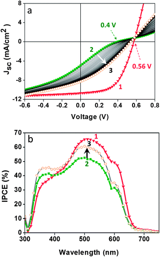 | ||
| Fig. 3 Organic solar cells withV2O5 hydrate as the hole transport layer in the inverted configuration (glass/FTO/TiO2/P3HT:PCBM/V2O5/Ag). Photovoltaic response of the cells fabricated from a freshly prepared (1) or a 24 h-old (2) V2O5–IPA solution. Using the fresh solution obviates the need for photo-activation of the device in air, as shown in the IV-curves and IPCE spectra from (2) to (3). Measurements were taken at 100 mW cm−2 AM1.5G. | ||
Since the only difference in the fabrication of the two OSCs was the V2O5 HTL, we attributed the need for photo-annealing to the V2O5 thin film properties that are probably affected by the interaction between V2O5 with IPA.62,66,67 Layered vanadium(V) oxides in their hydrated state tend to accommodate foreign molecules in their interlayer region,64,66–68 including organic compounds such as alcohols.69 Alcohols intercalate, via their –OH group, at the polar site of V2O5. In this partially reversible reaction the H2O molecules of V2O5 hydrate are exchanged with alcohol molecules, leading to the reduction of V2O5 from V+5to V+4. V2O5 reduces relatively quickly when in solution with organic molecules, as indicated by a gradual change in the colour of the solution from red (indicative of V5+) to green (indicative of the reduction of V5+ to V4+). Thus, the thin film obtained from the 24 h-old V2O5–IPA solution could be partially reduced and therefore photo-annealing is required in order to eliminate the undesirable shunts and inflection points (S-shape IV curve) and to achieve maximum power conversion efficiency.4,70,71,80
To understand the changes that we observed in the OSCs as a function of the freshness of the V2O5–IPA solution, we characterised the V2O5 thin films by XPS, UPS and optical analyses.76–78 Fig. 4a shows the XPS spectra of the V2O5·0.5H2O thin films fabricated from the fresh (red) and 24 h-old (green) solutions. The binding energy (BE) values of the main peaks and their assignment are detailed in Table 2.
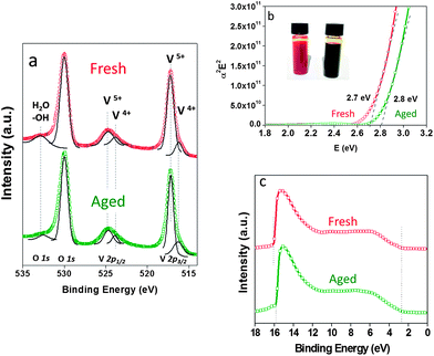 | ||
| Fig. 4 XPS (a), band gap (b) and UPS (c) spectra of the V2O5·0.5H2O thin film obtained from freshly prepared (red) or 24 h-old (green) V2O5–IPA solution. | ||
| Peak | Fresh (red) | 24 h-old (green) | Assignment |
|---|---|---|---|
| V2p3/2 | 516.20 | 516.20 | V4+ |
| V2p3/2 | 517.20 | 517.20 | V5+ |
| V2p1/2 | 524.75 | 524.70 | V5+ |
| O 1s | 529.95 | 529.90 | O2− |
| O 1s | 533.20 | — | H2O |
XPS analyses revealed only slight differences in the intensity of the spectra between the two films (see ESI Fig. S3†). Despite these small differences, the two thin films gave very similar XPS results: the main peaks of V2p3/2 and V2p1/2 were almost identical. The characteristic peaks of V2O5 are observed at 517 eV and 524 eV (corresponding to V5+), and at 529.9 eV (the O 1s from the O2− ions). The XPS plot was subject to a Lorentzian–Gaussian fitting: the region of the V5+ peak at 517 eV reveals a shoulder at ca. 516 eV. This peak is attributed to the presence of V4+, which is commonly observed in the hydrated form of V2O572 as well as in reduced films.73 But, it is not present in a crystalline V2O5 film that has been subjected to thermal evaporation or annealed at high temperatures, as these procedures eliminate all water.72 This shoulder at 516 eV has also been observed by Ziberberg et al., in the XPS analyses of a V2O5 thin film (10 nm) obtained from vanadium(V)-oxytriisopropoxide (ViPr). However, they attributed the presence of the V4+ peak to air exposure and not to any possible organic residues from the ViPr (despite having observed residual carbon by XPS).
The calculated composition analyses of the films show that V4+ accounts for a very small amount (less than 10% of total V), indicating that both thin films are partially reduced if compared to the stoichiometric V2O5. Taking into account the atomic ratio of V and O (expected V:O ratio of 1:2.46 for V2O5), we can be aware of the content of oxygen vacancies in the films. A deviation from the stoichiometric V:O ratio, of 1:2.46, was observed for both films, an indication of the presence of oxygen vacancies that arise from the reduction of V2O5, as expected.72 Moreover, the peak at 533.2 eV of the O 1s is slightly higher in intensity for the film made from the freshly prepared solution, and almost disappears in the thin film made from the aged V2O5–IAP solution (as can be seen in Fig. 4a and S3†). This is in good agreement with the replacement of the water molecules intercalated in V2O5 by the IAP molecules in solution. Once prepared as a thin film, the IAP evaporates from the V2O5 layer leaving behind a thin film without (or at least less amount) of water molecules.
We can infer from these results that both thin films are partially reduced: the film prepared with fresh solution, by water, and the film prepared with the 24 h-old solution, by IPA.
The optical band gap (BG), calculated from Tauc's formula, plot of α2E2 against photo energy,75 is shown in Fig. 4b. It reveals a slight difference in BGs between the thin films fabricated from either fresh (red) or 24 h-old (green) V2O5–IPA solution, with values of 2.7 eV and 2.8 eV, respectively. The full He I scan of the ultraviolet photoelectron spectroscopy (UPS) analyses of the films is shown in Fig. 4c. The work function (WF) values obtained were 5.15 eV (fresh) and 5.5 eV (24 h-old), respectively, as reflected in the photoemission offset around 16 eV. These values are in good agreement with WF values of thin films of V2O5 fabricated in air.15 Finally, the values for the ionisation potential (IP), defined as the energy difference between the valence band (VB) edge and the vacuum level (Ev), are 7.66 eV (fresh) and 8.0 eV (24 h-old).
These results permitted the construction of the band energy diagram for both thin films as shown in Fig. 5. To calculate the voltage of the OSC, we used the LUMO level of ZnO at 4.4 eV57 and the HOMO level obtained experimentally for V2O5 at 5.0 to 5.16 eV. The latter yields a Voc value of 0.56 V to 0.6 V, which is in good agreement with the experimental Voc values obtained for the OSCs shown in Fig. 3 (and very similar to the Voc values between 0.56 and 0.58 V observed in Fig. 1). However, we were unable to arrive at a clear conclusion regarding the Voc value of the solar cell that contained the V2O5 thin film made from the 24 h-old (green) V2O5–IPA solution (experimentally 0.38 V) since there is a wide range of possible reduction stages for V2O5 that can be detected in IPA over time. Thus, based on the experimental and calculated values of Voc, we reasoned that the fabrication steps followed to obtain the V2O5 thin film affect the final photovoltaic response of the OSC. Moreover, the final Voc of the device is probably chiefly dictated by the semiconductor oxide layers and by the HOMO/LUMO levels of the donor and acceptor materials of the active P3HT:PCBM layer.
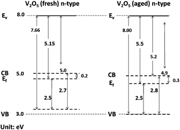 | ||
| Fig. 5 Band diagrams for V2O5 thin films obtained from freshly prepared (a) or 24 h-old and (b) V2O5–IPA solutions. Ev: vacuum level; CB: conduction band; Ef: Fermi level; and VB: valence band. | ||
3.3 OSCs with normal and inverted configuration with an Ag back metal electrode
One of the limitations for the fabrication of normal-configuration OSCs by low-temperature solution processing techniques is the requirement of low work function back metal electrodes, such as Al.10,58 While Ag electrodes can easily be printed from solution, there is currently no viable route for printing a stable Al electrode.10 This is a drawback that also limits the manufacture, by printing techniques, of tandem or multi-junction OSCs in the normal-configuration. Thus, in this section, we want to demonstrate that the fabrication of OSCs applying an Ag metal electrode is possible for both configurations when the V2O5 HTL is applied.Fig. 6 shows the solar cells' energy band diagrams (a and b), the solar cell architectures in both configurations (c and d), and the corresponding IV curves and IPCE analyses for both types of devices (e and f). The photovoltaic parameters obtained are detailed in Table 3. The band energy diagrams in Fig. 6a and b are represented in relation to the relative energy levels of the acceptor (PCBM) and the donor (P3HT). The experimental values observed for the V2O5 thin film (5.1 eV) are very close to the energy level of the P3HT, and in good agreement with the work function of the Ag and the FTO electrodes responsible for the hole and electron collection respectively. Comparison of the photovoltaic response indicates a very similar behaviour, with Voc ranging between 0.54 V and 0.56 V and the FF between 47 and 48%. The main difference is observed on the Jsc, which is lower for the OSC in the normal configuration in comparison with the inverted configuration. The difference in Jsc also limits the PCEs, which is observed between 2.6% and 3% for the inverted configuration, and at around 2% for the normal configuration (see Table 3). This difference in PCE is further validated by the corresponding IPCE responses: with 70% and 40% for inverted and the normal configuration, respectively. The dissimilarity in the performance between the two types of OSCs can be attributed to the greater light reflection and the UV-filter effect imposed by the V2O5 layer on the device. In the case where the device is illuminated from the FTO/V2O5 side (see Fig. 6d and e), the V2O5 layer could be acting as a UV-filter, limiting the amount of light reaching the cell. Adsorption spectra of the ZnO and the V2O5 layers are shown in Fig. 6f. V2O5 adsorbs at wavelengths up to 450 nm while in the inverted configuration (Fig. 6c), light enters the device from the FTO/ZnO side, where the ZnO layer blocks only the UV wavelength region below 380 nm. An interesting aspect observed is the value of Voc that is almost the same for both types of devices. This is an indication that the LUMO level of ZnO at 4.4 eV and the HOMO level of V2O5 at 5.16 eV can be used to calculate the Voc of the normal configuration OSC.57 In the same way it was described before for the inverted OSC in Section 3.2. OSCs applying V2O5 as the HTL5,10,13,14,16–20,81–83 have been usually reported with an Ag metal electrode in the inverted configuration,5,10,15,57 and an Al or Ca electrode in the normal configuration.14,19,21,58 In our work, the photovoltaic response of both types of OSCs seems to be independent of the Ag back metal electrode employed. This makes the OSCs amenable to fabrication by printing methods as the Ag metal electrode can simply be printed from solution.5,10,44,79 This also could be a step forward to the fabrication of more compatible recombination layers for TmOSCs.10
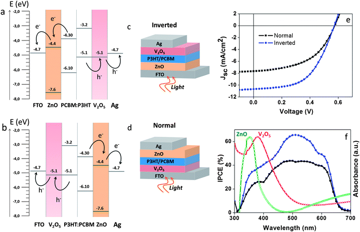 | ||
| Fig. 6 Schematic representation of the band energy diagram for the inverted (a) and normal (b) configuration of organic solar cells containing ZnO as the electron transport layer and water-based, solution-processed V2O5 as the hole transport layer. The architecture of the inverted (e) and the normal (d) configuration OSCs. IV curves (c) and IPCE spectra (f) of the OSCs in each configuration. In both cases, an Ag back metal electrode was used. Measurements were taken at 100 mW cm−2 AM1.5G. | ||
| Device structure | Voc (V) | Jsc (mA cm−2) | FF (%) | PCE (%) |
|---|---|---|---|---|
| a Average value from six samples. | ||||
| Inverted | ||||
| Glass/FTO/ZnO/P3HT:PCBM/V2O5/Ag | 0.540 ± 0.01 | 9.54 ± 1.1 | 47.20 ± 1.9 | 2.58 ± 0.2 |
| Normal | ||||
| Glass/FTO/V2O5/P3HT:PCBM/ZnO/Ag | 0.565 ± 0.01 | 7.65 ± 0.3 | 48.35 ± 2.3 | 2.10 ± 0.2 |
| Reference cell | ||||
| Glass/FTO/TiO2/P3HT:PCBM/V2O5/Ag | 0.563 ± 0.01 | 10.69 ± 0.3 | 50.49 ± 1.9 | 3.09 ± 0.1 |
The selection of the adequate back metal electrode in OSCs has been the subject of extensive research work. The OSCs that have been studied to date contain only one oxide semiconductor used as the ETL (usually TiO2, TiOx or ZnO), and PEDOT:PSS as the HTL.44,84 Since the use of TMOs as both ETL and HTL is relatively new, we have not found any other work in which a high work-function metal electrode (e.g. Ag) is used for the normal configuration OSC. Greiner et al. recently described the effect of metal electrodes on the work function and band structure of MoO3 at metal/metal oxide interfaces. The reduction of the oxide (from Mo6+ to Mo3+) in contact with the metal electrode results in a lower work function of the oxide, and the maximum value depends on the thickness of the oxide layer.85 Hadipour et al. have employed an Ag metal electrode in different OSCs in the normal configuration, including the ones in which MoO3 is the HTL. However, a thin layer of Ca between the active layer of P3HT:PCBM and the Ag metal electrode was employed for the normal configuration OSCs.86 Lidzey et al. have reported a study on different back metal electrodes in normal configuration OSCs in which MoO3 is also the HTL.87 The authors fabricated OSCs of the type ITO/MoO3/PCDTBT:PC70BM/metal electrode (note that no ETL was applied between the active layer and the metal electrode), using diverse, thermally evaporated metals (Ag, Al, Ca, Ca/Ag and Ca/Al). The final photovoltaic performance of the solar cells was very similar in all cases, showing only slight differences among the devices. The authors chose the Ca/Al back electrode as the best one, owing to its slightly better photovoltaic response. Although their work involved only one TMO as the HTL (MoO3) and did not entail the use of any ETL, it is the closest research work related to the one presented here by us (in terms of set-up and results). It also supports the idea that the photovoltaic performance of normal configuration OSCs containing metal oxides is probably independent of the back metal electrode used. Despite the advances made by Lidzey et al., our group and others, substantial studies are needed to clarify the role of the back electrode in these TMO-based OSCs.
3.4 Outdoor stability analyses: normal vs. inverted OSCs, effects of UV filter
The lifetime stability of the OSCs was analyzed under outdoor conditions for 1000 h. Fig. 7 shows the normalized PCE response observed with time for the inverted and normal configuration OSCs applying V2O5 as the HTL. Initial results revealed that the light irradiation dose affects drastically the OSCs' response as can be observed in Fig. 7. A peak on PCE can be observed almost every time the light irradiation drops below 1 sun (100 W m−2), especially for irradiance between 0.6 and 0.8 suns (see also ESI, Fig. S4 and S5†). Moreover, the lifetime analyses revealed better stability and longer lifetimes for OSCs with normal-configuration, staying at T80 even after 1000 h of analysis. The inverted-configuration OSCs revealed strong degradation reaching T80 after only 320 h of analysis. This response was unexpected since the OSCs with inverted-configuration are well-known to display higher stability (even under ambient conditions) than the normal configuration OSCs.47–50,88 In our solar cells, we consider that the greater stability of the normal configuration OSC is partly due to the UV-filter effect that the V2O5 layer can impose on the device when illuminated from the FTO/V2O5 side, as already described.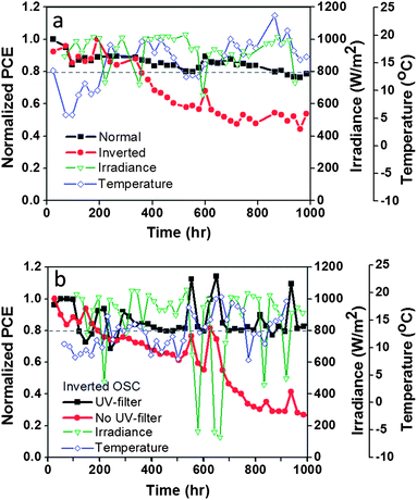 | ||
| Fig. 7 Outdoor stability analysis of sealed OSCs containing water-based, solution-processed V2O5 as the hole transport layer. Comparison of normalised PCE response: (a) normal configuration vs. inverted configuration (both without the UV filter); and (b) with the UV filter vs. without the UV filter (both in inverted configuration). The cells were analysed outdoors in Barcelona, Spain (41.30° N, 2.09° W). The PCE values were calculated using the maximum irradiance level per day. Average temperatures: 10 to 15 °C (day) and 5 to 7 °C (night). Average RH: 70%. Normal configuration: glass/FTO/V2O5/P3HT:PCBM/ZnO/Ag. Inverted configuration: glass/FTO/ZnO/P3HT:PCBM/V2O5/Ag. | ||
In order to demonstrate that the OSCs would be more stable in the absence of UV light, we applied a UV filter to the inverted-configuration OSC. Two samples, one with the UV filter and the other without, were analysed outdoors under the same conditions. The filter (an adhesive UV filter film that cuts UV light below 400 nm) was applied on top of the test cell. Fig. 7b shows the observed response for the first 1000 h of analysis. The control sample performed just like the inverted OSC analysed in Fig. 7a, reaching T60 at ∼500 h and T40 at ∼1000 h. However, the sample with the UV filter remained at T80 for many hours and was still stable after ∼1000 h of testing. Thus we can demonstrate that elimination of UV light can improve the lifetime of the inverted-configuration OSC by several orders of magnitude.
In this work, we have demonstrated the high stability of OSCs containing V2O5·0.5H2O as the HTL despite the presence of water molecules in the layer. The degradation of the OSC lacking the UV filter indicates that V2O5 is photoactive under UV light, and that the active P3HT:PCBM layer or the Ag electrode can interact with the V2O5 HTL. Nevertheless, a UV filter is beneficial and improves the OSC’s stability.
4 Conclusions
In summary, we have demonstrated the first example of stable organic solar cells (OSCs) containing a layered V2O5 hydrate as the hole transport layer (HTL). V2O5 is processed from a water-based solution in air, resulting in a final thin film of formula V2O5·0.5H2O. The water molecules remain in the V2O5 layered structure at temperatures below 250 °C, which makes the thin film highly stable under real working conditions. The HTL was employed in OSCs in either the normal or the inverted configuration, in which Ag was used for the back metal electrode. These types of OSCs can be fabricated totally by solution-processing printing in air, as they do not require the Al electrode found in normal-configuration OSCs. XPS, UPS and optical characterisation of the V2O5 thin films revealed differences based on the age of the V2O5–isopropanol (IPA) solution used for film deposition. In films made with a 24 h-old solution, reduction of the oxide (from V5+ to V4+) by IPA meant that subsequent re-oxidation (by photo-annealing) was required to achieve optimal photovoltaic performance. In contrast, the films made with fresh V2O5–isopropanol solution directly exhibited peak performance and therefore did not require any photo-annealing. The normal-configuration OSCs do not require any photo-annealing because the V2O5 thin film is formed from an aqueous solution. Outdoor stability analyses of sealed OSCs containing V2O5 as the HTL, in either the inverted or the normal configuration, revealed that the normal-configuration was highly stable. It remained at T80 even after 1000 h, probably due to the fact that it is illuminated from the FTO/V2O5 side and to the UV-filtering effect of the V2O5 layer. In contrast, the inverted-configuration OSC, which is illuminated from the FTO/ZnO side, was far less stable. Our hypothesis on the effects of the V2O5 layer was corroborated by a subsequent test in which an inverted-configuration OSC, equipped with an external UV-filter, achieved comparable levels of stability to that of the normal-configuration OSC.Acknowledgements
We thank Aurelie Vanwaelscappel for the AFM image. We thank Guillaume Sauthier for his advice on the XPS and UPS analyses, and Prof. Frederik C. Krebs from the Technical University of Denmark (DTU) for providing the sample of the adhesive UV-filter employed for the stability/lifetime testing. We thank CONACYT (Mexico) for the PhD scholarship for G. T. E., the Erasmus fellowship programme for financial support for J. P., the Spanish Ministry of Economy and Competitively (MINECO) for the Consolider grant NANOSELECT CSD2007-00041, and the Xarxa de Referència en Materials Avançats per a l'Energia, XaRMAE (Reference Centre for Advanced Materials for Energy) of the Catalan government.Notes and references
- R. A. J. Janssen and J. Nelson, Adv. Mater., 2013, 25, 1847–1858 CrossRef CAS PubMed.
- H. Hoppe and N. S. Sariciftci, J. Mater. Res., 2004, 19, 1924–1945 CrossRef CAS.
- F. C. Krebs, S. A. Gevorgyan and J. Alstrup, J. Mater. Chem., 2009, 19, 5442–5451 RSC.
- M. R. Lilliedal, A. J. Medford, M. V. Madsen, K. Norrman and F. C. Krebs, Sol. Energy Mater. Sol. Cells, 2010, 94, 2018–2031 CrossRef CAS PubMed.
- T. T. Larsen-Olsen, T. R. Andersen, B. Andreasen, A. P. L. Böttiger, E. Bundgaard, K. Norrman, J. W. Andreasen, M. Jørgensen and F. C. Krebs, Sol. Energy Mater. Sol. Cells, 2012, 97, 43–49 CrossRef CAS PubMed.
- E. Lee, J. Kim and C. Kim, Sol. Energy Mater. Sol. Cells, 2012, 105, 1–5 CrossRef CAS PubMed.
- Z. Tan, L. Li, C. Cui, Y. Ding, Q. Xu, S. Li, D. Qian and Y. Li, J. Phys. Chem. C, 2012, 116, 18626–18632 CAS.
- S. R. Dupont, E. Voroshazi, P. Heremans and R. H. Dauskardt, Org. Electron., 2013, 14, 1262–1270 CrossRef CAS PubMed.
- O. Hagemann, M. Bjerring, N. C. Nielsen and F. C. Krebs, Sol. Energy Mater. Sol. Cells, 2008, 92, 1327–1335 CrossRef CAS PubMed.
- T. T. Larsen-Olsen, E. Bundgaard, K. O. Sylvester-Hvid and F. C. Krebs, Org. Electron., 2011, 12, 364–371 CrossRef CAS PubMed.
- R. Søndergaard, M. Helgesen, M. Jørgensen and F. C. Krebs, Adv. Energy Mater., 2011, 1, 68–71 CrossRef.
- N. Espinosa, H. F. Dam, D. M. Tanenbaum, J. W. Andreasen, M. Jørgensen and F. C. Krebs, Materials, 2011, 4, 169–182 CrossRef CAS.
- W. T. Chiang, S. H. Su, Y. F. Lin and M. Yokoyama, Jpn. J. Appl. Phys., 2010, 49, O4DK14 Search PubMed.
- K. Zilberberg, S. Trost, H. Schmidt and T. Riedl, Adv. Energy Mater., 2011, 1, 377–381 CrossRef CAS.
- K. Zilberberg, S. Trost, J. Meyer, A. Kahn, A. Behrendt, D. Lützenkirchen-Hecht, R. Frahm and T. Riedl, Adv. Funct. Mater., 2011, 21, 4776–4783 CrossRef CAS.
- S. R. Dupont, M. Oliver, F. C. Krebs and R. H. Dauskardt, Sol. Energy Mater. Sol. Cells, 2012, 97, 171–175 CrossRef CAS PubMed.
- C. Gong, H. B. Yang, Q. L. Song and C. M. Li, Org. Electron., 2012, 13, 7–12 CrossRef CAS PubMed.
- S. H. Su, W. K. Lin, W. T. Chiang, Y. F. Lin and M. Yokoyama, Jpn. J. Appl. Phys., 2012, 51, 02BK03 CrossRef.
- H. Q. Wang, N. Li, N. S. Guldal and C. J. Brabec, Org. Electron., 2012, 13, 3014–3021 CrossRef CAS PubMed.
- M. Hajzeri, A. S. Vuk, L. S. Perse, M. Colovic, B. Herbig, U. Posset, M. Krzmanc and B. Orel, Sol. Energy Mater. Sol. Cells, 2012, 99, 67–72 CrossRef PubMed.
- F. Xie, W. C. H. Choy, C. Wang, X. Li, S. Zhang and J. Hou, Adv. Mater., 2013, 25, 2051–2055 CrossRef CAS PubMed.
- J. C. Bernede, S. Houari, D. Nguyen, P. Y. Jouan, A. Khelil, A. Mokrani, L. Cattin and P. Predeep, Phys. Status Solidi A, 2012, 209, 1291–1297 CrossRef CAS.
- R. Betancur, M. Maymóc, X. Elias, L. T. Vuong and J. Martorell, Sol. Energy Mater. Sol. Cells, 2011, 95, 735–739 CrossRef CAS PubMed.
- Q. Chen, B. J. Worfolk, T. C. Hauger, U. Al-Atar, K. D. Harris and J. M. Buriak, ACS Appl. Mater. Interfaces, 2011, 3, 3962–3970 CAS.
- M. D. Irwin, B. Buchholz, A. W. Hains, R. P. H. Chang and T. J. Marks, Proc. Natl. Acad. Sci. U. S. A., 2008, 105, 2783–2787 CrossRef CAS.
- M. D. Irwin, J. D. Servaites, D. B. Buchholz, B. J. Leever, J. Liu, J. D. Emery, M. Zhang, J. H. Song, M. F. Durstock, A. J. Freeman, M. J. Bedzyk, M. C. Hersam, R. P. H. Chang, M. A. Ratner and T. J. Marks, Chem. Mater., 2011, 23, 2218–2226 CrossRef CAS.
- C. H. Poh, C. K. Poh, G. Bryant, W. Belcher and P. Dastoor, Proc. SPIE, 2011, 8204OW Search PubMed.
- K. X. Steirer, J. P. Chesin, N. E. Widjonarko, J. J. Berry, A. Miedaner, D. S. Ginley and D. C. Olson, Org. Electron., 2010, 11, 1414–1418 CrossRef CAS PubMed.
- K. X. Steirer, P. F. Ndione, N. E. Widjonarko, M. T. Lloyd, J. Meyer, E. L. Ratcliff, A. Kahn, N. R. Armstrong, C. J. Curtis, D. S. Ginley, J. J. Berry and D. C. Olson, Adv. Energy Mater., 2011, 1, 813–820 CrossRef CAS.
- N. Sun, G. Fang, P. Qin, Q. Zheng, M. Wang, X. Fan, F. Cheng, J. Wan and X. Zhao, Sol. Energy Mater. Sol. Cells, 2010, 94, 2328–2331 CrossRef CAS PubMed.
- D. W. Zhao, P. Liu, X. W. Sun, S. T. Tan, L. Ke and A. K. K. Kyaw, Appl. Phys. Lett., 2009, 95, 153304 CrossRef.
- A. K. K. Kyaw, X. W. Sun, C. Y. Jiang, G. Q. Lo, D. W. Zhao and D. L. Kwong, Appl. Phys. Lett., 2008, 93 CrossRef CAS.
- Y. Kinoshita, R. Takenaka and H. Murata, Appl. Phys. Lett., 2008, 92, 243309 CrossRef.
- C. Girotto, E. Voroshazi, D. Cheyns, P. Heremans and B. P. Rand, ACS Appl. Mater. Interfaces, 2011, 3, 3244–3247 CAS.
- H. Schmidt, H. Flügge, T. Winkler, T. Bülow, T. Riedl and W. Kowalsky, Appl. Phys. Lett., 2009, 94, 243302 CrossRef.
- A. G. F. Janssen, T. Riedl, S. Hamwi, H. H. Johannes and W. Kowalsky, Appl. Phys. Lett., 2007, 91, 073519 CrossRef.
- C. Tao, S. Ruan, G. Xie, X. Kong, L. Shen, F. Meng, C. Liu, X. Zhang, W. Dong and W. Chen, Appl. Phys. Lett., 2009, 94, 043311 CrossRef.
- C. Tao, G. Xie, F. Meng, S. Ruan and W. Chen, J. Phys. Chem. C, 2011, 115, 12611–12615 CAS.
- M. G. Varnamkhasti, H. R. Fallah, M. Mostajaboddavati, R. Ghasemi and A. Hassanzadeh, Sol. Energy Mater. Sol. Cells, 2012, 98, 379–384 CrossRef PubMed.
- L. J. Zuo, X. X. Jiang, L. G. Yang, M. S. Xu, Y. X. Nan, Q. X. Yan and H. Z. Chen, Appl. Phys. Lett., 2011, 99, 183306 CrossRef.
- M. T. Greiner, M. G. Helander, W.-M. Tang, Z.-B. Wang, J. Qiu and Z.-H. Lu, Nat. Mater., 2012, 11, 76–81 CrossRef CAS PubMed.
- H. Ma, H. L. Yip, F. Huang and A. K. Y. Jen, Adv. Funct. Mater., 2010, 20, 1371–1388 CrossRef CAS.
- W. J. Potscavage Jr, A. Sharma and B. Kippelen, Acc. Chem. Res., 2009, 42, 1758–1767 CrossRef PubMed.
- R. Steim, F. R. Kogler and C. J. Brabec, J. Mater. Chem., 2010, 20, 2499–2512 RSC.
- Z. B. Wang, M. G. Helander, M. T. Greiner, J. Qiu and Z. H. Lu, Phys. Rev. B: Condens. Matter Mater. Phys., 2009, 80, 235325 CrossRef.
- K. Norrman, M. V. Madsen, S. A. Gevorgyan and F. C. Krebs, J. Am. Chem. Soc., 2010, 132, 16883–16892 CrossRef CAS PubMed.
- B. Andreasen, D. M. Tanenbaum, M. Hermenau, E. Voroshazi, M. T. Lloyd, Y. Galagan, B. Zimmernann, S. Kudret, W. Maes, L. Lutsen, D. Vanderzande, U. Wurfel, R. Andriessen, R. Rosch, H. Hoppe, G. Teran-Escobar, M. Lira-Cantu, A. Rivaton, G. Y. Uzunoglu, D. S. Germack, M. Hosel, H. F. Dam, M. Jorgensen, S. A. Gevorgyan, M. V. Madsen, E. Bundgaard, F. C. Krebs and K. Norrman, Phys. Chem. Chem. Phys., 2012, 14, 11780–11799 RSC.
- R. Rosch, D. M. Tanenbaum, M. Jorgensen, M. Seeland, M. Barenklau, M. Hermenau, E. Voroshazi, M. T. Lloyd, Y. Galagan, B. Zimmermann, U. Wurfel, M. Hosel, H. F. Dam, S. A. Gevorgyan, S. Kudret, W. Maes, L. Lutsen, D. Vanderzande, R. Andriessen, G. Teran-Escobar, M. Lira-Cantu, A. Rivaton, G. Y. Uzunoglu, D. Germack, B. Andreasen, M. V. Madsen, K. Norrman, H. Hoppe and F. C. Krebs, Energy Environ. Sci., 2012, 5, 6521–6540 Search PubMed.
- D. M. Tanenbaum, M. Hermenau, E. Voroshazi, M. T. Lloyd, Y. Galagan, B. Zimmermann, M. Hosel, H. F. Dam, M. Jorgensen, S. A. Gevorgyan, S. Kudret, W. Maes, L. Lutsen, D. Vanderzande, U. Wurfel, R. Andriessen, R. Rosch, H. Hoppe, G. Teran-Escobar, M. Lira-Cantu, A. Rivaton, G. Y. Uzunoglu, D. Germack, B. Andreasen, M. V. Madsen, K. Norrman and F. C. Krebs, RSC Adv., 2012, 2, 882–893 RSC.
- G. Teran-Escobar, D. M. Tanenbaum, E. Voroshazi, M. Hermenau, K. Norrman, M. T. Lloyd, Y. Galagan, B. Zimmermann, M. Hosel, H. F. Dam, M. Jorgensen, S. Gevorgyan, S. Kudret, W. Maes, L. Lutsen, D. Vanderzande, U. Wurfel, R. Andriessen, R. Rosch, H. Hoppe, A. Rivaton, G. Y. Uzunoglu, D. Germack, B. Andreasen, M. V. Madsen, E. Bundgaard, F. C. Krebs and M. Lira-Cantu, Phys. Chem. Chem. Phys., 2012, 14, 11824–11845 RSC.
- F. J. Zhang, D. W. Zhao, Z. L. Zhuo, H. Wang, Z. Xu and Y. S. Wang, Sol. Energy Mater. Sol. Cells, 2010, 94, 2416–2421 CrossRef CAS PubMed.
- D. Y. Kim, G. Sarasqueta and F. So, Sol. Energy Mater. Sol. Cells, 2009, 93, 1452–1456 CrossRef CAS PubMed.
- J. Li, Q. Y. Bao, H. X. Wei, Z. Q. Xu, J. P. Yang, Y. Q. Li, S. T. Lee and J. X. Tang, J. Mater. Chem., 2012, 22, 6285–6290 RSC.
- S. Kouijzer, S. Esiner, C. H. Frijters, M. Turbiez, M. M. Wienk and R. A. J. Janssen, Adv. Energy Mater., 2012, 2, 945–949 CrossRef CAS.
- V. S. Gevaerts, A. Furlan, M. M. Wienk, M. Turbiez and R. A. J. Janssen, Adv. Mater., 2012, 24, 2130–2134 CrossRef CAS PubMed.
- Y. Yuan, J. Huang and G. Li, Green, 2011, 1, 65–80 CrossRef.
- C. P. Chen, Y. D. Chen and S. C. Chuang, Adv. Mater., 2011, 23, 3859–3863 CAS.
- I. Hancox, L. A. Rochford, D. Clare, M. Walker, J. J. Mudd, P. Sullivan, S. Schumann, C. F. McConville and T. S. Jones, J. Phys. Chem. C, 2013, 117, 49–57 CAS.
- D. Gupta, M. M. Wienk and R. A. J. Janssen, Adv. Energy Mater., 2013, 3, 782–787 CrossRef CAS.
- M. Lira-Cantu and F. C. Krebs, Sol. Energy Mater. Sol. Cells, 2006, 90, 2076–2086 CrossRef CAS PubMed.
- I. Gonzalez-Valls and M. Lira-Cantu, Energy Environ. Sci., 2010, 3, 789–795 CAS.
- J. Livage, Chem. Mater., 1991, 3, 578–593 CrossRef CAS.
- M. O. Reese, S. A. Gevorgyan, M. Jørgensen, E. Bundgaard, S. R. Kurtz, D. S. Ginley, D. C. Olson, M. T. Lloyd, P. Morvillo, E. A. Katz, A. Elschner, O. Haillant, T. R. Currier, V. Shrotriya, M. Hermenau, M. Riede, K. R. Kirov, G. Trimmel, T. Rath, O. Inganäs, F. Zhang, M. Andersson, K. Tvingstedt, M. Lira-Cantu, D. Laird, C. McGuiness, S. Gowrisanker, M. Pannone, M. Xiao, J. Hauch, R. Steim, D. M. DeLongchamp, R. Rösch, H. Hoppe, N. Espinosa, A. Urbina, G. Yaman-Uzunoglu, J.-B. Bonekamp, A. J. J. M. van Breemen, C. Girotto, E. Voroshazi and F. C. Krebs, Sol. Energy Mater. Sol. Cells, 2011, 95, 1253–1267 CrossRef CAS PubMed.
- J. Livage, Coord. Chem. Rev., 1998, 178–180, 999–1018 CrossRef CAS.
- M. Nabavi, C. Sanchez and J. Livage, Eur. J. Solid State Inorg. Chem., 1991, 28, 1173–1192 CAS.
- J. Livage, Mater. Res. Bull., 1991, 26, 1173–1180 CrossRef CAS.
- J. Livage, Coord. Chem. Rev., 1999, 190–192, 391–403 CrossRef CAS.
- J. Livage, F. Beteille, C. Roux, M. Chatry and P. Davidson, Acta Mater., 1998, 46, 743–750 CrossRef CAS.
- S. Kittaka, H. Yamamoto, S. Higuma and T. Sasaki, J. Chem. Soc., Faraday Trans., 1992, 88, 715–718 RSC.
- M. Jørgensen, K. Norrman, S. A. Gevorgyan, T. Tromholt, B. Andreasen and F. C. Krebs, Adv. Mater., 2012, 24, 580–612 CrossRef PubMed.
- A. Manor, E. A. Katz, T. Tromholt and F. C. Krebs, Sol. Energy Mater. Sol. Cells, 2012, 98, 491–493 CrossRef CAS PubMed.
- V. Bondarenka, S. Kaciulis, Z. Martunas, A. Reza, G. J. Babonas and A. Pasiskevicius, Lith. J. Phys., 2008, 48, 341–348 CrossRef CAS.
- J. Światowska-Mrowiecka, F. Martin, V. Maurice, S. Zanna, L. Klein, J. Castle and P. Marcus, Electrochim. Acta, 2008, 53, 4257–4266 CrossRef PubMed.
- D. Liu, Y. Liu, B. B. Garcia, Q. Zhang, A. Pan, Y. H. Jeong and G. Cao, J. Mater. Chem., 2009, 19, 8789–8795 RSC.
- M. Benmoussa, A. Outzourhit, R. Jourdani, A. Bennouna and E. L. Ameziane, Act. Passive Electron. Compon., 2003, 26, 245–256 CrossRef.
- J. Meyer, K. Zilberberg, T. Riedl and A. Kahn, J. Appl. Phys., 2011, 110, 033710 CrossRef.
- Z. Y. Li and Q. H. Wu, J. Mater. Sci.: Mater. Electron., 2008, 19, S366–S370 CrossRef CAS.
- A. L. Pergament, E. L. Kazakova and G. B. Stefanovich, J. Phys. D: Appl. Phys., 2002, 35, 2187–2197 CrossRef CAS.
- H. L. Yip and A. K. Y. Jen, Energy Environ. Sci., 2012, 5, 5994–6011 CAS.
- I. Gonzalez-Valls, D. Angmo, S. A. Gevorgyan, J. Sebastián Reparaz, F. C. Krebs and M. Lira-Cantu, J. Polym. Sci., Part B: Polym. Phys., 2013, 51, 272–280 CrossRef CAS.
- P. Lutsyk and Y. Vertsimakha, Mol. Cryst. Liq. Cryst., 2005, 426, 265–276 CrossRef CAS.
- G. Li, C. W. Chu, V. Shrotriya, J. Huang and Y. Yang, Appl. Phys. Lett., 2006, 88, 253503 CrossRef.
- A. Ojala, H. Burckstummer, J. Hwang, K. Graf, B. von Vacano, K. Meerholz, P. Erk and F. Wurthner, J. Mater. Chem., 2012, 22, 4473–4482 RSC.
- E. D. Gomez and Y. L. Loo, J. Mater. Chem., 2010, 20, 6604–6611 RSC.
- M. T. Greiner, L. Chai, M. G. Helander, W. M. Tang and Z. H. Lu, Adv. Funct. Mater., 2013, 23, 215–226 CrossRef CAS.
- A. Hadipour, D. Cheyns, P. Heremans and B. P. Rand, Adv. Energy Mater., 2011, 1, 930–935 CrossRef CAS.
- D. C. Watters, J. Kingsley, H. Yi, T. Wang, A. Iraqi and D. Lidzey, Org. Electron., 2012, 13, 1401–1408 CrossRef CAS PubMed.
- E. Voroshazi, B. Verreet, A. Buri, R. Müller, D. Di Nuzzo and P. Heremans, Org. Electron., 2011, 12, 736–744 CrossRef CAS PubMed.
Footnote |
| † Electronic supplementary information (ESI) available. See DOI: 10.1039/c3ee42204f |
| This journal is © The Royal Society of Chemistry 2013 |