 Open Access Article
 This Open Access Article is licensed under a Creative Commons Attribution-Non Commercial 3.0 Unported Licence
Plasmon-induced oxidation of gold nanoparticles on TiO2 in the presence of ligands
Yohei Konishi,
Ichiro Tanabe† and
Tetsu Tatsuma*
Institute of Industrial Science, University of Tokyo, 4-6-1 Komaba, Meguro-ku, Tokyo 153-8505, Japan. E-mail: tatsuma@iis.u-tokyo.ac.jp; Fax: +81-3-5452-6338; Tel: +81-3-5452-6336
First published on 5th July 2013
Abstract
The mechanism of plasmon-induced charge separation of gold nanoparticles (Au NPs) on TiO2 was investigated with the help of anionic ligands. Au NPs are oxidized in the presence of KX (X = SCN, Br or Cl), chiefly via direct oxidation to [AuX4]−. The reactivity of Au NPs depends on the solution pH, the type of anion ligands and the excitation wavelength, suggesting that the photopotential of Au NPs during plasmon-induced charge separation depends on both the flatband potential of TiO2 and the energy of irradiated photons. The results indicate that the reactivity and efficiency of the plasmon-induced charge separation and accompanying reactions can be tuned and optimized by changing those factors.
1. Introduction
Noble metal nanoparticles (NPs) absorb and scatter light at specific wavelengths due to localized surface plasmon resonance (LSPR). As their resonance wavelength and intensity depend largely on the particle size, shape, interparticle distance and dielectric environment, they exhibit a variety of colours.1,2 In our past research, we found that Au,3,4 Ag4,5 and Cu6 NPs on TiO2 or ZnO exhibit plasmon-induced charge separation, which is caused by light irradiation at LSPR wavelengths. Stable Au NPs have been applied to plasmon-based photocatalysis3,7,8 and photovoltaic cells.3,4,9–11 On the other hand, less stable Ag NPs undergo photo-oxidation and dissolution,12 which have been applied to multicolour,5,13 infrared14 and high speed15 photochromism, as well as photoinduced multicolour control of single NP16 and photomorphing gels.17 However, the mechanisms of the plasmon-induced charge separation have not yet been elucidated completely, and learning the details of the phenomenon may lead to an improvement of the reaction efficiency and the development of other applications.We have reported that TiO2 electrodes modified with Au3,4 or Ag4,18 NPs exhibit negative potential shifts and anodic currents under illumination. In contrast, Au9,19 or Ag9,20 NPs coated with TiO2 exhibit positive potential shifts and cathodic currents. On the basis of these results, we concluded that the charge separation is caused by electron transfer from metal NPs to TiO2, which is also supported in related studies by other groups.7,8,10,11,21–23
As mentioned above, Au NPs are generally so stable that the plasmon-induced charge separation does not cause their oxidative dissolution.3 In our previous research, however, we have achieved the plasmon-induced oxidative dissolution of Au NPs with the aid of I− (KI aqueous solution) and developed a multicolour change material, which is more resistive to white light than a Ag-based material.24 However, it is yet to be elucidated whether the Au dissolution is predominantly due to direct oxidation (Au + 4I− → [AuI4]− + 3e−, E° = +0.56 V vs. NHE) or indirect oxidation via I3− (3I− → I3− + 2e−, E° = +0.55 V, then 2Au + 3I3− → 2[AuI4]− + I−), because the potential of the former reaction is close to that of the latter (Fig. 1a). To obtain further information about this, here we used other ligands, i.e. Br−, Cl− and SCN−. In the case of Br− and Cl−, the potentials of the direct oxidation are far more negative than the oxidation potentials of the halide ion to tri-halide ion. Also, in a solution of SCN−, the indirect mechanism would not hold as SCN3− is known to be unstable in aqueous media.25 In addition, examination of the reactions in the presence of different ligands and at different pH values sheds light on the photopotentials of Au NPs during the plasmon-induced charge separation.
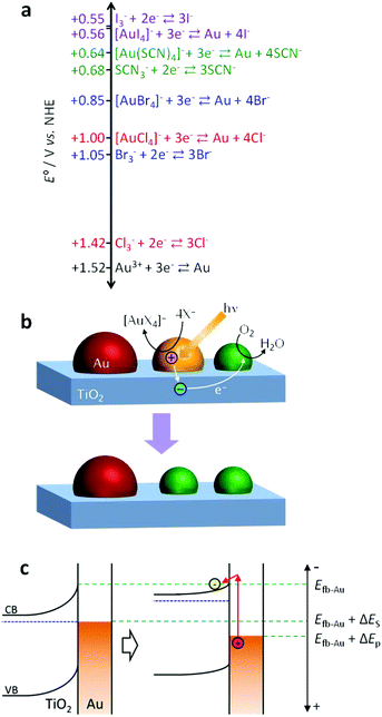 | ||
| Fig. 1 (a) Values of the standard electrode potential E° for oxidative coordination of Au with anionic ligands (X−) and oxidation of the anions to X3−. (b) Mechanism of spectral dip formation for the Au NP–TiO2 system. (c) Potential shifts of Au NPs and TiO2 due to the plasmon-induced charge separation in an open circuit system. | ||
2. Experimental
Preparation of a TiO2 film and Au NPs
A TiO2 film loaded with Au NPs was prepared as previously reported.24 A TiO2 film was prepared on a Pyrex glass substrate from a commercial anatase sol (STS-21, Ishihara, 75% aq.) by a spin-coating method (at 1500 rpm for 10 s) and calcined at 723 K for 1 h. Au NPs were deposited photocatalytically on the TiO2 film as follows. A mixture of 10 mM aqueous solution of HAuCl4 and ethanol (1![[thin space (1/6-em)]](https://www.rsc.org/images/entities/char_2009.gif) :9 by volume, 32 mL cm−2) was cast on the TiO2 film and left for 15 min, followed by rinsing with water. The mixture was cast again and the film was irradiated with UV light (260–370 nm, 25 mW cm−2) for 10 s. Electrons in the TiO2 valence band (VB) are excited to the conduction band (CB), and used for the reduction of [AuCl4]− to Au NPs. The corresponding generated holes in the VB are consumed by oxidation of ethanol.
:9 by volume, 32 mL cm−2) was cast on the TiO2 film and left for 15 min, followed by rinsing with water. The mixture was cast again and the film was irradiated with UV light (260–370 nm, 25 mW cm−2) for 10 s. Electrons in the TiO2 valence band (VB) are excited to the conduction band (CB), and used for the reduction of [AuCl4]− to Au NPs. The corresponding generated holes in the VB are consumed by oxidation of ethanol.
Photoinduced reactions
Extinction (= absorption + scattering) spectra were collected using a V-670 spectrophotometer (Jasco). The as-prepared Au NP–TiO2 sample was soaked in 0.5 M KSCN, KBr or KCl aqueous solution until the spectrum was stabilized. Then, the sample in the solution was irradiated with 600–700, 700–800 or 800–1000 nm light (10 mW cm−2) for 30 min. The light source was a Xe lamp (Luminar Ace LA-410UV, Hayashi Watch Works) (600–700 nm) or a halogen lamp (HA-150UX, Myutron) (700–800 and 800–1000 nm) equipped with a long-pass filter (SCF-50S-60R, SCF-50S-70R or CLDM-50S, Sigma Koki) and a short-pass or band-pass filter (FSWP-800-25.0M or SPF-1000-1.00, CVI Melles Griot; ITF-50S-83RT, Sigma Koki).For monochromatic light irradiation (4 mW cm−2) in 0.5 M KCl at pH 7, 8 or 9 (adjusted with KOH), a band-pass filter (full width at half maximum = 10 nm) for 700 nm (Asahi Spectra) or 800 or 900 nm (CVI Melles Griot) was used with the Xe lamp (700 nm) or the halogen lamp (800 and 900 nm).
3. Results and discussion
Spectral dip formation
The deposited Au NPs show an extinction peak at 545 nm and a tail extending to the near infrared region (∼1000 nm) (Fig. 2a) as a result of the formation of NPs with various size and anisotropy on the contact area with TiO2 which exhibit different LSPR wavelengths.24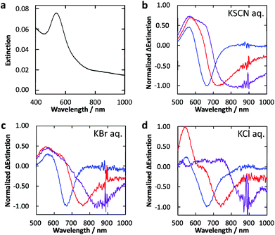 | ||
| Fig. 2 (a) Extinction spectrum of Au NPs deposited photocatalytically on the TiO2 film. (b–d) Normalized difference extinction spectra of Au NPs on TiO2 after 600–700 (blue), 700–800 (red) and 800–1000 (purple) nm light irradiation (10 mW cm−2, 30 min) in 0.5 M aqueous solution of (b) KSCN, (c) KBr and (d) KCl. | ||
The Au NP-modified TiO2 sample was irradiated with 600–700, 700–800 or 800–1000 nm light (10 mW cm−2) in 0.5 M KSCN, KBr or KCl aqueous solution for 30 min. Normalized difference extinction spectra after the light irradiations are shown in Fig. 2b–d. In all these cases, extinction decreased preferentially at around the irradiation wavelengths and wavelength-selective extinction dips were formed. These spectral changes are explained in terms of selective oxidation and dissolution of resonant Au NPs to [AuX4]− (X: halogen or SCN) (Fig. 1b).24 The peaks at ∼540 nm in the difference spectra are attributed to smaller NPs formed eventually by the dissolution, which exhibit LSPR at ∼540 nm.24 Small Au NPs deposited by recombination of the [AuX4]− ions and electrons transferred to TiO2 may also be responsible for the peaks.24,26
In the case of X = SCN, the dip formation must be caused by the direct oxidation (Au + 4SCN− → [Au(SCN)4]− + 3e−), because SCN3− is unstable in aqueous media,25 as described above. The direct oxidation should also be the major pathway in the case of X = Br and Cl, because the potentials for the direct oxidation are more negative than those for the X3− generation (Fig. 1a). In particular, the potential for Cl3− generation is even more positive than that of water oxidation.
Photoreactivity at different pH
Next we examined the dependence of the photoreactivity on the solution pH, which affects the flatband potential of TiO2 at the TiO2–solution interface Efb–sol. Actually, the flatband potential of TiO2 is known to shift by −0.06 V per pH unit due to deprotonation of surface hydroxyl groups.27 We irradiated the Au NP-modified TiO2 sample with monochromatic light at 700, 800 and 900 nm (4 mW cm−2, fwhm = 10 nm) in 0.5 M aqueous KCl at pH 7, 8 or 9 (adjusted with KOH; the film was damaged at pH 10). As a result, dip formation was observed at all the wavelengths at pH 7 (Fig. 3a), whereas it was not observed at 900 nm at pH 8 and 9 (Fig. 3b, c). The Efb–sol values were estimated for the TiO2 film without Au NPs by voltammetry to be −0.14, −0.20 and −0.25 V vs. NHE at pH 7, 8 and 9, respectively. On the other hand, the potential for the Au/[AuCl4]− redox couple EAu–Cl, which does not involve H+ or OH−, should not depend on pH.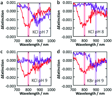 | ||
| Fig. 3 Difference extinction spectra of Au NPs on TiO2 after irradiation with 800 and 900 nm (4 mW cm−2, 30 min) light in 0.5 M KCl ((a) pH 7, (b) 8 and (c) 9) and (d) KBr (pH 9) aqueous solutions. | ||
There are two possible explanations for the suppression of the photoreactions at high pH. (I) If the TiO2 CB level at the TiO2–Au NP interface Efb–Au is not affected by the CB level at the TiO2–solution interface Efb–sol, the rise of the latter could slow down electron transport from the TiO2–Au NP interface to other parts of TiO2 and thereby lower the charge separation efficiency. However, the dependence of the reactivity on the excitation wavelength only at higher pH is not explained by this hypothesis. (II) If Efb–Au is affected by Efb–sol because the area of the TiO2–Au NP interface is so small, the photopotential at Au NPs may depend on pH. The photopotential may also depend on the excitation wavelength.
In the plasmon-induced charge separation, some electrons in a resonant Au NP should be transferred to TiO2 through the Schottky barrier at the TiO2–Au NP interface.3,19 The barrier height ΔES is estimated to be ∼1.2 eV or higher, as the electron affinity of nanoparticulate anatase TiO2 and the work function of Au are ∼3.9 eV28,29 and 5.1–5.47 eV,30,31 respectively. Sönnichsen et al.32 described that LSPR decays partially via inter- or intraband transition. However, it may not be reasonable to assume that those excited states are long-lived enough to be involved in the electron transfer from Au NPs to TiO2, unless electrons pass through trap states, if any, at the TiO2–Au interface. If not, it is likely that the electron transfer is due to hot electron injection or external photoelectric effect. Under irradiation of photons with an energy of ΔEp eV that is higher than the Schottky barrier height ΔES (i.e. ΔEp ≥ ΔES), those types of electron transfer may shift the potential of Au NPs positively up to Efb–Au + ΔEp V (Fig. 1c). If this is the case, the spectral dip formation should be suppressed when the Efb–Au + ΔEp is more negative than EAu–Cl + ΔEop, where ΔEop is the overpotential needed for the redox reaction. That is, the photoinduced redox reaction could be suppressed at high pH and at a long wavelength even if ΔEp ≥ ΔES.
Actually, the reaction occurs under 700 and 800 nm light (ΔEp = 1.77 and 1.55 eV, respectively) at pH 7–9, where Efb–Au + ΔEp = +1.30–+1.63 V vs. NHE on the assumption that Efb–Au = Efb–sol. Also, it occurs under 900 nm light (ΔEp = 1.38 eV) at pH 7 (Efb–Au + ΔEp = +1.24) but not at pH 8 and 9 (Efb–Au + ΔEp = +1.13–+1.18). Therefore, the threshold exists at +1.18–+1.24 V. The difference between this threshold potential and the standard electrode potential for the formation of [AuCl4]− (+1.00 V vs. NHE) may be explained in terms of the reaction overpotential and/or the difference between Efb–Au and Efb–sol.
Photoreactivity in the presence of different anions
Replacement of KCl with KBr resulted in dip formation in all the cases examined, even at pH 9 under 900 nm light (Fig. 3d), where the Efb–Au + ΔEp value is +1.13 V vs. NHE. This value is sufficiently positive compared with the standard potential for the formation of [AuBr4]− (+0.85 V vs. NHE; Fig. 1a), even taking the possible overpotential of 0.18–0.24 V into account. It is thus suggested that the photopotential of Au NPs is dominated by Efb and ΔEp. Since Efb is related not only to pH but also to the coexisting cations and semiconductor, these factors as well as the light wavelength would be optimized for intended reactions.4. Conclusions
Wavelength-selective spectral dip formation was observed for the Au NP–TiO2 system in the presence of KX (X = SCN, Br or Cl). These results suggest that the dip formation is caused by direct oxidation of Au NPs to [AuX4]−. The reactivity of Au NPs depends on both solution pH and excitation wavelength, suggesting that the photopotential of Au NPs depends on both the flatband potential of TiO2 and the energy of irradiated photons. The results indicate that the reactivity and efficiency of the plasmon-induced charge separation can be tuned and optimized by changing those factors.Acknowledgements
This work was supported in part by Grant-in-Aid for Scientific Research on Priority Area “Coordination Programming” (Area No. 2107) No. 24108708 and Grant-in-Aid for Scientific Research No. 25288063. I.T. acknowledges a JSPS Research Fellowship for Young Scientists.Notes and references
- S. Link and M. A. El-Sayed, J. Phys. Chem. B, 1999, 103, 8410 CrossRef CAS.
- T. Jensen, L. Kelly, A. Lazarides and G. C. Schatz, J. Cluster Sci., 1999, 10, 295 CrossRef CAS.
- Y. Tian and T. Tatsuma, J. Am. Chem. Soc., 2005, 127, 7632 CrossRef CAS.
- Y. Tian and T. Tatsuma, Chem. Commun., 2004, 1810 RSC.
- Y. Ohko, T. Tatsuma, T. Fujii, K. Naoi, C. Niwa, Y. Kubota and A. Fujishima, Nat. Mater., 2003, 2, 29 CrossRef CAS.
- T. Yamaguchi, E. Kazuma, N. Sakai and T. Tatsuma, Chem. Lett., 2012, 41, 1340 CrossRef CAS.
- E. Kowalska, R. Abe and B. Ohtani, Chem. Commun., 2009, 241 RSC.
- H. Kominami, A. Tanaka and K. Hashimoto, Chem. Commun., 2010, 46, 1287 RSC.
- Y. Takahashi and T. Tatsuma, Appl. Phys. Lett., 2011, 99, 182110 CrossRef.
- Z. H. Chen, Y. B. Tang, C. P. Liu, Y. H. Leung, G. D. Yuan, L. M. Chen, Y. Q. Wang, I. Bello, J. A. Zapien, W. J. Zhang, C. S. Lee and S. T. Lee, J. Phys. Chem. C, 2009, 113, 13433 CAS.
- P. Reineck, G. P. Lee, D. Brick, M. Karg, P. Mulvaney and U. Bach, Adv. Mater., 2012, 24, 4750 CrossRef CAS.
- T. Tatsuma, Bull. Chem. Soc. Jpn., 2013, 86, 1 CrossRef CAS.
- K. Naoi, Y. Ohko and T. Tatsuma, J. Am. Chem. Soc., 2004, 126, 3664 CrossRef CAS.
- E. Kazuma and T. Tatsuma, Chem. Commun., 2012, 48, 1733 RSC.
- N. Crespo-Monterio, N. Destouches, L. Bois, F. Chassagneux, S. Reynaud and T. Fournel, Adv. Mater., 2010, 22, 3166 CrossRef.
- I. Tanabe and T. Tatsuma, Nano Lett., 2012, 12, 5418 CrossRef CAS.
- T. Tatsuma, K. Takada and T. Miyazaki, Adv. Mater., 2007, 19, 1249 CrossRef CAS.
- K. Kawahara, K. Suzuki, Y. Ohko and T. Tatsuma, Phys. Chem. Chem. Phys., 2005, 7, 3851 RSC.
- N. Sakai, Y. Fujiwara, Y. Takahashi and T. Tatsuma, ChemPhysChem, 2009, 10, 766 CrossRef CAS.
- Y. Takahashi and T. Tatsuma, Nanoscale, 2010, 2, 1494 RSC.
- Y. Nishijima, K. Ueno, Y. Yokota, K. Murakoshi and H. Misawa, J. Phys. Chem. Lett., 2010, 1, 2031 CrossRef CAS.
- T. Tachikawa, T. Yonezawa and T. Majima, ACS Nano, 2013, 7, 263 CrossRef CAS.
- A. Furube, L. Du, K. Hara, R. Katoh and M. Tachiya, J. Am. Chem. Soc., 2007, 129, 14852 CrossRef CAS.
- Y. Konishi, I. Tanabe and T. Tatsuma, Chem. Commun., 2013, 49, 606 RSC.
- O. Barbosa-Filho and A. J. Monhemius, Trans. Inst. Min. Metall. C, 1994, 103, C105 CAS.
- K. Matsubara, K. L. Kelly, N. Sakai and T. Tatsuma, Phys. Chem. Chem. Phys., 2008, 10, 2263 RSC.
- A. Fujishima, A. Sakamoto and K. Honda, Seisan Kenkyu, 1969, 21, 450 CAS.
- R. Könenkamp, Phys. Rev. B: Condens. Matter, 2000, 61, 11057 CrossRef.
- F. Lenzmann, J. Krueger, S. Burnside, K. Brooks, M. Grätzel, D. Gal, S. Rühle and D. Cahen, J. Phys. Chem. B, 2001, 105, 6347 CrossRef CAS.
- H. B. Michaelson, J. Appl. Phys., 1977, 48, 4729 CrossRef CAS.
- D. E. Eastman, Phys. Rev. B: Solid State, 1970, 2, 1 CrossRef.
- C. Sönnichsen, T. Franzl, T. Wilk, G. von Plessen, J. Feldmann, O. Wilson and P. Mulvaney, Phys. Rev. Lett., 2002, 88, 077402 CrossRef.
Footnote |
| † Present address: Department of Chemistry, School of Science and Technology, Kwansei Gakuin University, Sanda, Hyogo 669-1337, Japan. |
| This journal is © The Royal Society of Chemistry 2013 |