 Open Access Article
 This Open Access Article is licensed under a
 Creative Commons Attribution 3.0 Unported Licence
Electronic structure and soft-X-ray-induced photoreduction studies of iron-based magnetic polyoxometalates of type {(M)M5}12FeIII30 (M = MoVI, WVI)
Karsten
Kuepper
*ab,
Christine
Derks
b,
Christian
Taubitz
b,
Manuel
Prinz
b,
Loïc
Joly
c,
Jean-Paul
Kappler
c,
Andrei
Postnikov
de,
Wanli
Yang
f,
Tatyana V.
Kuznetsova
g,
Ulf
Wiedwald
a,
Paul
Ziemann
a and
Manfred
Neumann
b
aInstitute of Solid State Physics, Ulm University, Albert-Einstein-Allee 11, 89069 Ulm, Germany. E-mail: kkuepper@uos.de
bDepartment of Physics, University of Osnabrück, Barbarastr. 7, 49069 Osnabrück, Germany
cIPCMS UCMS 7504 CNRS—Université de Strasbourg, 23 rue du Loess, BP 43, 67034 Strasbourg Cedex 2, France
dUniversity of Lorraine, LCP-A2MC 1 Bd Arago, F-57078 Metz, France
eFaculty of Physics, University of Bielefeld, P.O. Box 100131, D-33501 Bielefeld, Germany
fAdvanced Light Source, Lawrence Berkeley National Laboratory, Berkeley, CA 94720, USA
gInstitute of Metal Physics, Russian Academy of Sciences, Ural Div., S. Kovalevskaya str. 18, 620990 Ekaterinburg, Russia
First published on 23rd January 2013
Abstract
Giant Keplerate-type molecules with a {Mo72Fe30} core show a number of very interesting properties, making them particularly promising for various applications. So far, only limited data on the electronic structure of these molecules from X-ray spectra and electronic structure calculations have been available. Here we present a combined electronic and magnetic structure study of three Keplerate-type nanospheres—two with a {Mo72Fe30} core and one with a {W72Fe30} core by means of X-ray absorption spectroscopy, X-ray magnetic circular dichroism (XMCD), SQUID magnetometry, and complementary theoretical approaches. Furthermore, we present detailed studies of the Fe3+-to-Fe2+ photoreduction process, which is induced under soft X-ray radiation in these molecules. We observe that the photoreduction rate greatly depends on the ligand structure surrounding the Fe ions, with negatively charged ligands leading to a dramatically reduced photoreduction rate. This opens the possibility of tailoring such polyoxometalates by X-ray spectroscopic studies and also for potential applications in the field of X-ray induced photochemistry.
1. Introduction
Polyoxometalates (POM) make a fascinating class of inorganic compounds which, in a sense, closes a gap between “conventional” transition-metal (TM) oxides and molecular magnets. They link, by mediation of oxygen, the TM atoms together into structures in which quite strict rules govern the emerging short-range order. Other than imposing a crystal-type periodicity, these rules of chemical bonding may give rise to huge molecules of fancy shapes and beautiful sophistication.1 Such entities may further be connected into a molecular crystal, allowing variations depending on the particularly used “glue” of solvent molecules. The measurable electronic, magnetic or vibrational properties of polyoxometalates are, however, primarily shaped by the physics within individual molecular units, weakly coupled between themselves.Possible “use” of POMs, beyond the chemist's professional satisfaction and the general aesthetical reward, leaves space to fantasy, e.g. in the sense of confinement/transport of smaller molecules or in staging/tuning magnetic interactions. The latter aspect underlines the closeness of POMs to metallo-organic molecules, or molecular magnets, in view of similar mechanisms (and strength) of interatomic magnetic coupling, and, generally, of the chemical bonding involved. Even if the bare POM carcase is typically free of “conventionally organic” carbon or nitrogen, they are frequent members of auxiliary details keeping the POM molecule together.
Although POMs have been a subject of study for some time by a number of groups worldwide, e.g., 2–7 we emphasize the long-term efforts by the group of Achim Müller in Bielefeld, to which we owe the introduction into the subject and the synthesis of systems used in our present study.
In particular, the giant neutral Keplerate-type molecules, {Mo72M30} (M = FeIII, CrIII, VIV, and LnIII), show a number of intriguing properties making them extremely promising, potential candidates for various applications and models, i.e. quasicrystals8 and water exchange in minerals.9 Recently, a remarkable self-recognition phenomenon, leading to separate blackberry-type structures of the {Mo72Fe30} and {Mo72Cr30} molecules in dilute solutions, has been reported.10 Moreover, such types of Keplerates with 30 transition-metal ions (e.g., FeIII or CrIII), symmetrically placed on an icosidodecahedral surface, are model compounds for a mesoscopic magnetic kagomé lattice at low temperatures.11–13 In particular, the magnetic properties of the neutral {Mo72Fe30} molecule (formula of the compound: [Mo72Fe30O252(CH3COO)10{Mo2O7(H2O)}{H2Mo2O8(H2O)}3(H2O)91]·ca. 150H2O ≡ 1 ≡ 1a·ca. 150H2O) have been investigated in a number of experimental and theoretical studies, including notably magnetic ones.12–17 Also, recently, a {W72Fe30}-type cluster (formula of the compound Na6(NH4)20[FeIII(H2O)6]2[{(WVI)WVI5O21(SO4)}12{(Fe(H2O))30}(SO4)13(H2O)34] ca. 200H2O ≡ 2 ≡ Na6(NH4)20[FeIII(H2O)6]2·2a·ca. 200H2O), where molybdenum atoms of the pentagonal units are replaced by tungsten ones, has been reported.18 While the 30 FeIII ions in this anion form a spherical network based on corner-shared triangles as in the {Mo72Fe30} molecule, there are differences in detail. First, the electron delocalization of the 3d electrons of the FeIII ions is somewhat weaker than those in 1, resulting in a weakened antiferromagnetic Fe–Fe interaction in 2 in comparison with that in 1. Second, there are significant differences in the chemistry of the ligands. The {W72Fe30} cluster 2 contains 25 SO42− instead of the 10 acetate ligands in 1, with the consequence that 2 is negatively charged (1 is neutral). A {Mo72Fe30} cluster with SO42− ligands has also been synthesized (formula of the compound Na9K3[K20⊂MoVI70FeIII30O252(SO4)24(H2O)75]·ca. 140H2O ≡ 3 ≡ Na9K33a·ca. 140H2O).19
The magnetic properties of metallo-organic complexes are of common interest due to the ongoing miniaturization of future memory devices. So-called single molecular magnets and related metallo-organic compounds are one potential vision for active functionals in future devices.
In the present study, we probe two of POM systems by different tools of X-ray spectroscopy. Such tools, especially when applied in combination and supported by first-principle calculations, are powerful in revealing information about distribution of electronic states and chemical bonding. Regarding the Fe30-based Keplerate-type compounds described above, no X-ray spectroscopic study of the electronic and chemical structures is available to date. Furthermore, X-ray magnetic circular dichroism (XMCD) at transition metal L edges is an advanced technique since it enables one to determine spin and orbital magnetic moments separately.20
One important issue which arises in this relation is potential “radiation damage”. X-ray-induced photochemistry, investigated by means of soft XAS, has been reported for two Fe-based metallo-organic complexes.21–24 These studies addressed potential mechanisms for the photo-oxidation/photoreduction/ligand-photolysis effects, which could also have been induced by the cleavage of chemical bonds between the transition metal and ligands for different reasons.
Soft XAS in the total electron yield (TEY) mode has a probing depth of a few nanometers only, suggesting that many secondary electrons are generated, which may play an important role in explaining the radiation-damage effects. Furthermore, it has been demonstrated that the damage effects can be retarded by the presence of “electron reservoirs” via molecule–substrate interactions.23 George et al.22 have reported that the observed X-ray induced photochemistry depends not only on the Fe valence but also on the ligand structure. This leads to the question of whether, and how, the X-ray induced “damage” effects in metallo-organic complexes can be “tailored” by means of their coordination chemistry. This offers an interesting alternative view onto X-ray-induced photochemistry as an opportunity to learn more about hitherto uncharacterized metal sites, rather than a cause of undesirable potential damage. However, a detailed spectroscopic study of chemical and electronic structures of metallo-organic compounds requires care, and one always has to consider potential soft-X-ray-induced modifications at both the transition metal and the ligand sites.
This paper aims to address two gaps in knowledge. First, because we wanted to investigate the topic of soft-X-ray-induced photoreduction in Fe-based metallo-organic complexes, we performed a detailed XAS study (in dependence of the overall photon flux) at the Fe L2,3 edges and the OK edge of 1, 2, and 3. We report a tendency toward Fe3+ to Fe2+photoreduction in all three molecules, although this process was significantly slower for molecules 2 and 3. This observation might be related to the presence of negatively charged SO42− ligands. These results also demonstrate the possibility that (soft) X-rays can be used as an active, rather than passive, probe of metallo-organic complexes.
Second, we performed a detailed study of the electronic and magnetic properties by means of soft XAS and XMCD in combination with first-principles electronic-structure calculations and charge-transfer multiple simulations.
2. Experimental and theoretical procedures
We probed the Fe3+-to-Fe2+photoreduction of the two Mo72Fe30 molecules (1 and 3) by means of Fe L2,3 edge XAS, using the total electron yield (TEY), at the Russian–German Beamline (RGBL) at BESSY II. We used the full flux of the dipole beamline and recorded a series of Fe L2,3 edge XAS on different spots on both molecules, with the samples being at room temperature. Each scan was completed in approximately 14 min.A comparable XAS study (also using TEY as detection mode) of the W72Fe30(SO4−) (2) and Mo72Fe30(Ac) (1) was carried out at room temperature at the Advanced Light Source, beamline 8.0.1, using the X-ray fluorescence end station of the University of Tennessee at Knoxville.25 Photons with energies of 500–750 eV were provided to the end station via a spherical 925-lines per mm-grating monochromator. The undulator-based beamline delivers a flux on the order of 1012 photons s−1 at Fe L edge photon energies around 700 eV. In order to minimize radiation damage effects, we used the high energy flank of the undulator gap to reduce the incoming photon flux to around 5–10% of the maximum photon flux for the first scan on each fresh sample spot. Each scan was completed in approximately 8 min.
The XMCD experiments were performed at the surface and interface microscopy (SIM) beamline of the Swiss Light Source (SLS). We used the 7 T cryomagnetic TBT-XMCD end station, working with a 3He–4He dilution setup in order to reach base temperatures of around 0.7 K.26 The sample with W72Fe30 core (2) was pasted on carbon tape before connecting the sample holder to the cryostat coldfinger. The spectra were recorded using the total electron yield (TEY). The undulator-based beamline delivers a flux on the order of 1012 photons s−1 at Fe L edge photon energies of around 700 eV. In order to minimize radiation damage effects, we tuned the beamline optics in order to reduce the incoming photon flux to around 1–2% of the maximum photon flux.
Magnetization measurements were performed with a Quantum Design MPMS SQUID magnetometer.
First-principles density-functional calculations were performed by the SIESTA method,27,28 which uses norm-conserving pseudopotentials in combination with numerical atom-centered strictly confined basis functions. Exchange-correlation potential was taken after the generalized gradient approximation (GGA) in the formulation of Perdew–Burke–Ernzerhof.29
The molecule (neutral Fe30Mo72-acetate, or (6-)-charged Fe30W72-sulfate) was placed in a cubic simulation cell having a 36 Å edge, preventing an overlap of basis functions across the cell boundary with the molecule's spurious replicas. Basis functions were generated by the split-norm technique, the standard one in SIESTA. Typically, the quality of the basis set was “double-zeta with polarization orbitals”,30 except for the Fe 3d status, which was of triple-zeta quality. An earlier calculation by the same method on another (Ni-based) oxovanadate system is described by Postnikov et al.31
Fe L2,3 edge XAS spectra were simulated within the charge-transfer multiplet model using the TT-multiplet program.32–34 After the atomic energy levels of the initial (2pn3dm) and final (2pn−13dm+1) states were calculated and reduced to 80% of their Hartree–Fock values (see Table 1), an octahedral crystal field was considered. Finally, we accounted for charge transfer by introducing 3dm+1L states and broadened the simulated spectra, considering lifetime broadening and spectrometer resolution.
| Fe2+ 2p63d6 initial | Fe2+ 2p53d7 final | Fe2+ 2p63d7L initial | Fe2+ 2p53d8L final | Fe3+ 2p63d5 initial | Fe3+ 2p53d6 final | Fe3+ 2p63d6L initial | Fe3+ 2p53d7L final | |
|---|---|---|---|---|---|---|---|---|
| Slater integrals | ||||||||
| F23d3d | 10.966 | 11.779 | 9.762 | 10.623 | 12.043 | 12.818 | 10.966 | 11.779 |
| F43d3d | 6.815 | 7.327 | 6.018 | 6.560 | 7.535 | 8.023 | 6.815 | 7.327 |
| F22p3d | 6.793 | 6.143 | 7.446 | 6.793 | ||||
| G12p3d | 5.004 | 4.467 | 5.566 | 5.004 | ||||
| G32p3d | 2.844 | 2.538 | 3.166 | 2.844 | ||||
| Spin–orbit coupling | ||||||||
| LS2p | 8.200 | 8.202 | 8.199 | 8.200 | ||||
| LS3d | 0.000 | 0.000 | 0.000 | 0.000 | 0.059 | 0.074 | 0.052 | 0.067 |
3. Results and discussion
3.1 Soft-X-ray-radiation-induced Fe photoreduction
To gain more knowledge of the exact nature of the underlying mechanism of the soft-X-ray-induced photoreduction process for Fe ions in 1, 2, and 3, we measured a series of Fe L2,3 edge XAS for both 1 and 2 systems (Fig. 1). These measurements were performed at an undulator-based beamline (see Experimental and theoretical procedures section), whereby we first reduced the photon flux to approximately 10% of its maximal intensity for the first Fe L2,3 edge scans of molecules 1 and 2. Next, we doubled the flux with each completed set of XAS performed at the Fe L2,3 edges untill maximum photon flux was reached. We observed a significant Fe3+ to Fe2+ reduction in both molecules. It is noteworthy that the Fe3+ ions in the (charge neutral) acetate-containing molecule 1 were significantly faster at reducing to Fe2+ than those in the sulfate-containing molecule 2 (see also Fig. 1). After a total of four XAS scans at the Fe L2,3 edges from fitting the measured spectra to charge-transfer multiplet calculations (more details can be found in the Experimental and theoretical procedures section), it can be estimated that only 12.5% of Fe3+ ions were left in molecule 1, but 37.5% remained in 2. The observed difference in the Fe photoreduction rates may be due to the fact that for molecule 1 the coordination is acetate and for 2 it is SO42−.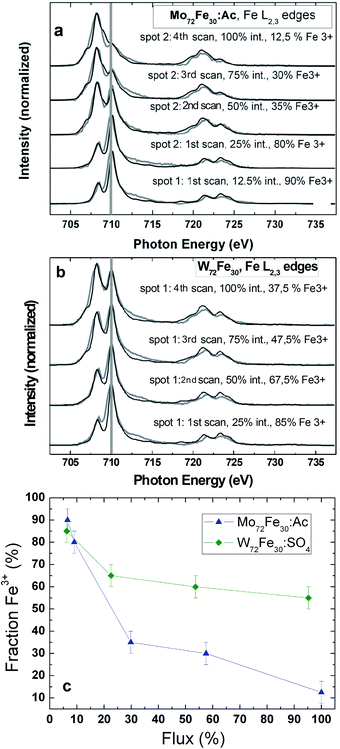 | ||
| Fig. 1 (a) Fe L2,3 edge XAS series of 1, and (b) 2; grey lines represent the experimental data; black lines represent the corresponding simulated spectra, which were obtained by superimposing corresponding fractions of the simulated Fe3+ and Fe2+ spectra. (c) Fraction of Fe3+ (derived from the corresponding multiplet simulations) versus the percentage X-ray photon flux time for the XAS series shown in the top panel. | ||
In Fig. 2, we present Fe L2,3 edge XAS series for molecules 1 and 3, taken at the Russian–German Beamline at BESSY II. All scans were acquired with the full intensity of the dipole beamline. The charge-neutral molecule 1 undergoes a relatively rapid Fe3+ to Fe2+ photoreduction (Fig. 2c). After only three scans across the Fe L2,3 edges, we found a 75% fraction of Fe2+ ions, as concluded from a comparison with the corresponding superimposed multiplet simulations. It is notable that much faster Fe3+ to Fe2+ photoreduction processes (within one single Fe L2,3 edge XAS scan) have been observed for a star-shaped Fe4 single magnetic molecule,24 where the Fe3+ ions are coordinated within an octahedral environment comprising four oxygen atoms and two nitrogen ligands. Also, for molecule 3 (Fig. 2a and 2b), a Fe3+ to Fe2+ photoreduction can be observed. The difference is that in 3 with its SO42− ligands, the soft X-ray induced photoreduction rate at the Fe site is noticeably lower than that in 1. Two different spots of 3 have been probed with different storage-ring currents (spot 1: 294–260 mA, spot 2: 188–173 mA). After approximately seven scans on spot 1 (scans 6 and 7 were taken only across the Fe L3 edge), there was still a 47.5% fraction of Fe3+ ions, and on spot 2, we observed a 40% Fe3+ fraction. We present a more quantitative analysis in Fig. 2d. The two series taken on 3 almost perfectly match when calibrated to the overall percentage photon flux, whereas a much more rapid photoreduction of 1 leads to a much steeper curve in this plot. Moreover, it is possible to fit the observed Fe3+ to Fe2+ photoreduction process observed for 3 by considering a simple exponential decay (solid black and orange fits in Fig. 2d). This may be an indication that the soft X-ray induced Fe photoreduction process, at least in these molecules, likely occurs within a single step, ruling out the possibility that two or more parallel processes occur on different slopes and timescales. We conclude that the different coordination chemistry seems to have a significant influence on the timescale of the soft X-ray induced Fe3+ to Fe2+ photoreduction process. The observed soft X-ray induced photoreduction may have several potential reasons.22,23,35,36 Whereas photo-oxidation under soft X-ray exposure dominates in Fe(0) and Fe(I) coordination complexes, photoreduction is found for Fe(III) and Fe(IV) based metallo-organic complexes.22 Also potential related phenomena such as ligand photolysis and/or ligand to metal charge transfer might be of importance.35 Very recently a counterion dependence of an observed Mn3+ to Mn2+ photoreduction reduction rate in (Mn6IIICrIII)3+ complexes has been reported.36 In these complexes the soft X-ray induced photoreduction rate was supposed to be lower in the presence of oxidizing counterions since these might release fewer electrons under soft X-ray exposure which may mediate the photoreduction process. Whereas we cannot exclude any of the above mentioned potential reasons for the photoreduction studies in this work, a plausible qualitative interpretation of this is that the observed photoreduction likely occurs because of the electrons liberated by the soft-X-ray excitation from the (ligand) atoms surrounding the transition-metal center.22 As these are then transferred from the ligand to the metal centers, one can quantitatively understand why molecules with the negatively charged SO42− ligands exhibit a lower photoreduction rate independent of the overall X-ray flux. The negative ligands “screen” the electrons of the surrounding matrix, leading to a repulsive potential. As previously described, the presence of “electron reservoirs” via metallic substrates can also lead to weaker radiation-damage effects.23 We also want to mention that, as to the charge transfer multiplet simulations, the crystal-field strength of the Fe2+ ions is noticeably lower (0.2 eV) than that of the original Fe3+ ions (0.8 eV), indicating major changes in the local crystal-field environment (and subsequently the Fe–O bonding length) around the Fe ions during the photoreduction process.
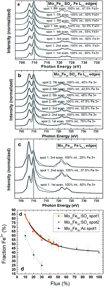 | ||
| Fig. 2 (a) First series of Fe L2,3 edge XAS of molecule 3 (spot 1); grey lines represent the experimental data; black lines represent the corresponding simulated spectra that were obtained by superimposing corresponding fractions of the simulated Fe3+ and Fe2+ spectra. (b) Second series of Fe L2,3 edge XAS of molecule 3 (spot 2). (c) Series of Fe L2,3 edge XAS of molecule 1. (d) Fraction of Fe3+ (derived from the corresponding multiplet simulations) versus the percentage of overall X-ray-photon flux for the three XAS series, including exponential fits (solid lines) for the two series taken on 3. | ||
3.2 Electronic and magnetic structure
To start a DFT calculation, one needs to specify a realistic structural model. Although the crystal structure, including solvent molecules, is known, we preferred to organize calculations for isolated molecular units, stripping them of solvent and defining, if needed, their net charge. Specifically, two systems have been selected for the present calculation:
1. Mo72Fe30O252(CH3COO)10{Mo2O7(H2O)}{H2Mo2O8(H2O)}3(H2O)91 (1a) or Fe30Mo80O398C20H226 (754 atoms), denoted henceforth as Fe30Mo72-acetate, whose structure is described in the literature.38 The Fe30(Mo6O15)12 ball, supplemented inwards and outwards with oxygen atoms and water molecules, is interwoven internally by 10 CH3COO− ions, one Mo2O7(H2O)2−, and three H2Mo2O8(H2O)2− groups, as described in the literature,38 and has a zero nominal charge.
2. [Na6(NH4)20{(WVI)WVI5O21(SO4)}12{Fe(H2O)}30(SO4)13(H2O)34]6− (Na6(NH4)20·2a) or Fe30W72O416N20H208S25Na6 (777 atoms), denoted henceforth as Fe30W72-sulfate, is structurally characterized in the literature.18 This structure is identical to the previous one with regard to the “soccer ball” composition (the Mo atoms now being replaced by W); however, the inner interweaving is executed by SO42− ions, which can dock in three different positions, as previously published.18 Furthermore, 20 ammonium cations are placed in the middle of, and slightly above, the hexagon faces of the “soccer ball,” and six sodium ions form an octahedral cage around the molecule, helping to further compensate for the excess negative charge. Two FeIII(H2O)6 units, which according to Todea et al.18 co-crystallize with the molecular ball, were not included in the calculation. Consequently, the nominal charge assigned to the remaining molecular unit was 6−.
A practical detail in setting up the calculation was the selection of a valid docking formation of the inner groups (acetate, Mo–O, or sulfate) inside the ball, from the many equivalent possibilities that were averaged in the crystallographic analysis. Although we assumed that the exact choice would not have a noticeable effect on the electronic structure, such a decision still had to be made. Obviously, the two systems, while being structurally similar, are quite different from the chemistry viewpoint and with respect to the technical details of calculation. Therefore, it could be instructive to compare the two systems, with the expected primary effect being due to the difference between Mo and W, and the secondary effect being due to different linkers inside the ball.
The question of the magnetic structure of Fe30 systems is not simple and deserves, in principle, a detailed discussion. Namely, in view of the system being apparently magnetically frustrated, an option of the non-collinear setting of local magnetic moments has been addressed.12 In the present study, we are predominantly interested in chemical bonding and spectral features, for which accessing a particular magnetic order is expected to have a less significant effect. Therefore, the results presented below correspond to the ferromagnetic setting of Fe magnetic moments. The calculation readily converges to a high-spin magnetic solution of 150 μB per molecule. This corresponds to the formal FeIII valence, consistent with chemical intuition. The spatial distribution of spin density can be characterized in two ways—by local partial (basis-function-projected) densities of states (DOS) and by spatially resolved charge/spin density. Local charge and magnetic states of different atoms can be further characterized by the respective (basis-dependent, and hence ambiguous) Mulliken populations. The valence-states Mulliken charge at the Fe sites corresponds to approximately 7.5, with a slight variation over different centers, instead of 8 for a free atom. This value is less than that observed for the nominally expected Fe3+ situation, in which local magnetic moments correspond to approximately 4 μB. However, this value is close to that obtained by the DFT characterization of other similar (octahedrally O-coordinated) Fe-based molecular magnets.39,40 As in the latter case, the local DOS at the Fe sites, shown in Fig. 3, reveal fully occupied majority-spin bands and empty minority-spin bands. Therefore, the local moment associated with a Fe atom must be approximately 5 μB, of which 1 μB is obviously delocalized over the neighboring oxygen centers. The Fe3d5↑3d0↓ configuration, when stripped of all 4s electrons, corresponds to the formal FeIII valence, thus resolving an apparent controversy. In terms of spatial spin-density distribution, this situation corresponds to the spherical shape of the half-filled 3d shell of Fe atoms, as seen in Fig. 4.
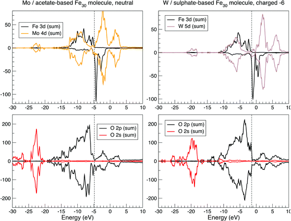 | ||
| Fig. 3 Selected local densities of states in Fe30Mo72-acetate (left panel) and Fe30W72-sulfate (right panel), summed up over all atoms of a given type, as calculated by the SIESTA method. See text for details. | ||
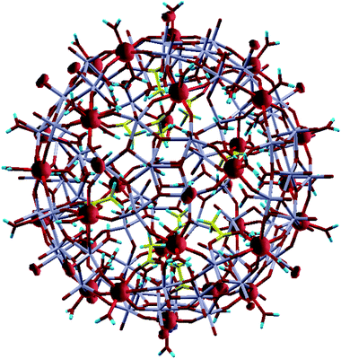 | ||
| Fig. 4 Spin-density isosurfaces of a conveniently chosen value in Fe30Mo72-acetate. The molecule is shown in wireframe representation. Fe atoms (on the ball surface) carry spin moments and are hidden within the (nearly spherical) spin-density isosurface bulbs. Mo atoms (grey-colored bunches) are also situated on the ball surface, interconnected by oxygen (red/dark) atoms. Further oxygen atoms are flanking Fe and Mo roughly along the ball radius, outwards and inwards. Most of these oxygen atoms, notably all outward ones from Fe and many inward ones from Fe and Mo, are parts of water molecules (where protons are shown as blue dashes); other inward oxygen atoms from Fe and Mo are connected via acetate or Mo–O linkers inside the ball. (The C atoms of acetate groups are shown in yellow). Outward O atoms from Mo atoms are standalone; some of them carry substantial spin moment (witnessed by “clouds” of spin-density isosurfaces). | ||
By comparing the DOS for both systems in Fig. 3, their hybridization structure seems to be quite similar, as revealed by the similarity of the Mo 4d and W 5d contributions, along with those of Fe and O between the two systems. Minor differences are only in part related to different chemistry, and otherwise reveal a slightly different structure (a more perfect ball, with less disturbing internal linkers, in the Fe30W72-sulfate system). The large size of the system marks a difference from “conventional” molecular magnets such as “ferric wheels”,39 for example, while the high density of the energy levels and the near disappearance of the band gap make the system behave like a semi-metal. Additional charging (as different values of nominal charge of the molecule from those stated above were also tested) does not lead to a dramatically different magnetic state.
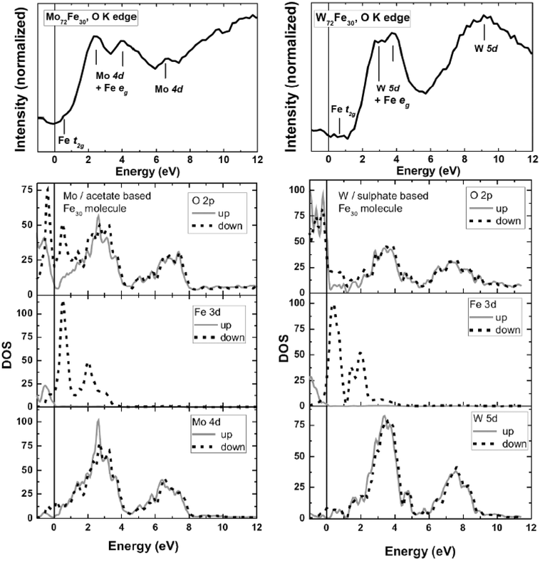 | ||
| Fig. 5 Top: O K edge XAS series of 1 (left) and 2 (right). The thick lines represent spectra taken at a low photon flux and a fresh spot of the corresponding sample. Bottom: Calculated unoccupied densities of states for 1 (left) and 2 (right). | ||
For molecule 2, we find an overall similar situation. Here the two main peaks representing hybridized O 2p/W 5d bands are located at 2 and 3 eV, respectively, followed by a rather broad feature spanning the range from ∼7 to 11 eV. Similar to the theoretical results of 1, the calculated unoccupied DOS of 2 is again somewhat shifted toward the Fermi level in comparison with that observed in the experimental O K XAS features. It is noteworthy that the theoretical results reproduce the overall features and shape of the experimental O K XAS, since there is no significant interaction of the oxygen core hole with the oxygen or metal valence electrons. Therefore the O K edge spectra can be described to large extent within a single-particle scheme. However, the observed differences might be related to the fact that the DFT calculations do not include core hole potentials.
Since the strength of hybridization between Mo 4d (W 5d) and the unoccupied O 2p states is significantly stronger than that of the Fe 3d states, the O K edge XAS spectra are dominated mostly by the hybridized Mo 4d (W 5d)/O 2p states, as discussed above. Apart from this, small features are located at 0.75 eV (1) and 0.5 eV (2), which can be associated with hybridized Fe 3d t2g states, based on comparison with the theoretical results (see Fig. 5). On the other side, the Fe 3d eg states are overlapped by the contributions from Mo 4d and W 5d, respectively.
Next, to discuss the Fe 3d states, we plotted the local density of the 3d states, summed up over all Fe sites of molecule 1 in the ferromagnetic configuration (Fig. 6). According to DFT calculations, the Fe-3d-related states responsible for magnetism are not strongly localized and flow onto neighboring atoms. At the same time, their “on-site” (Fe-centered) part clearly reveals the spatial organization of these states as either eg-like or t2g-like type (in corresponding energy intervals) in both occupied and unoccupied parts of the spectrum. We present a corresponding illustration of the Mo 4d states in Fig. 7.
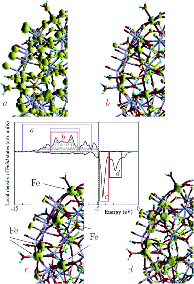 | ||
| Fig. 6 Central panel: local density of 3d states, summed up over all Fe sites of molecule 1 in the ferromagnetic configuration. The vertical dashed line separates occupied (shaded) and vacant states. The energy windows over which the Fe 3d states noticeably have an eg or t2g character are indicated by blue and red blocks, respectively. Four peripheral figures: charge densities integrated over energies within each of the indicated energy windows, namely in occupied majority-spin states (a, b) and unoccupied minority-spin states (c, d), shown by an isosurface for a conveniently chosen value in each case, to underline the symmetry of the charge density in the vicinity of the Fe centers. Only a fragment of the full Fe30 ball is shown in each case. Positions of the Fe atoms are indicated by arrows in the “c” panel. Note that the “a” panel comprises the result of integration over two intervals, separated by the “b” region. | ||
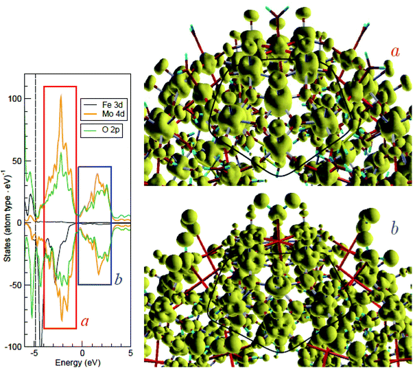 | ||
| Fig. 7 Isosurfaces of the (unoccupied) charge density summed up over two energy windows, indicated as “a” and “b” in the density of state shown on the left, where the dashed line at ∼−4 eV separates the occupied and vacant states. Only a part of molecule 1 is shown; MoMo5O5 pentagons are marked in both figures by a thick black line, which passes through oxygen atoms connecting the MoMo5O5 blocks with their neighboring Fe atoms (immediately outwards from each pentagon side). In the radial sense, every Mo atom is connected to an oxygen atom outwards and to a water molecule inwards; Fe atoms are connected to water molecules both outwards and inwards. Note a quasi-t2g character of the Mo 4d states in the “a” window (where the Fe 3d states are eg-like) and the quasi-eg character in the “b” window (where the states are missing). | ||
The Fe L2,3 edges XAS of all three molecules (1, 2, and 3) are quite similar (Fig. 1 and 2). Like the O K edge XAS discussed above, these spectra were also recorded with a noticeable reduced photon flux (see Experimental and theoretical procedures section) and at a new position for each scan. The shape of the spectrum clearly reflects a predominant Fe3+ character in an octahedral coordination. We obtained the best-fit solution from charge-transfer multiplet simulations by considering an octahedral crystal field of 0.2 eV for the Fe2+ simulation (10% spectral weight in Fig. 6) and 10 Dq = 0.8 eV for the Fe3+ simulation (90% spectral weight in Fig. 6). The Slater spin–orbit integrals are summarized in Table 1. The energy difference between configurations E(2p63dm) and E(2p53dm+1L) was set to 4.5 eV for Fe2+ and Fe3+. This resulted in a simulated 77.5% 3d6 and 22.5% 3d7L ground-state charge-transfer configuration for the Fe2+ ions, and an 80.8% 3d5 and 19.2% 3d6L configuration for Fe3+.
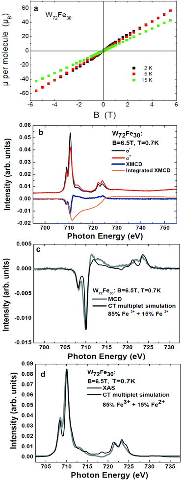 | ||
| Fig. 8 (a) Magnetization of W72Fe30 (2) at 2 K, 5 K, and 15 K as a function of field. (b) Fe L2,3 edges of 2 recorded with left and right circularly polarized X-rays, the corresponding XMCD signal, and its integral. These measurements were performed with a significantly reduced X-ray exposure (1–2% of the full beamline intensity) at a temperature of 0.7 K in an external field of 6.5 T. (c) and (d) Isotropic XMCD and isotropic XAS signals in comparison with charge-transfer multiplet simulations. | ||
(i) Weak initial Fe3+ to Fe2+ photoreduction processes cannot be entirely excluded.
(ii) The spin sum rule correction factor used has been derived for a perfectly octahedral and homogenous crystal field, whereas already small deviations formed, as in case of our systems, may lead to a somewhat different correction factor.42
(iii) Weak antiferromagnetic intermolecular interactions might be present in particular at low temperatures (T = 0.7 K).
(iv) As hinted by the first-principles calculations, some of the Fe-3d-related states responsible for magnetism are not strongly localized. Since XAS at transition metal L edges on ionic compounds is a probe of the localized electronic structure and coordination of the transition metal ion in question, possible “interstitial or hybridized spin states” may not be entirely included into the element specific XMCD signal.
However, it can be concluded that most of the Fe 3d spin states responsible for the magnetic moment (≥85%) are localized at the “on-site” (Fe-centered) part of the Fe 3d states of 2.
4. Summary
We investigated the electronic structure of three giant Keplerate-structural-type molecules with Mo72Fe30 and W72Fe30 cores by means of soft XAS and complementary theoretical approaches. For all three molecules, an Fe3+ to Fe2+ photoreduction process can be observed by means of Fe L2,3 edge XAS. The crystal-field strength of the Fe2+ ions is noticeably lower (0.2 eV) than that of the original Fe3+ ions, indicating major changes in the local crystal-field environment (and subsequently the Fe–O bonding length) around the Fe ions during the photoreduction process. Hence, the photoreduction process might be explained by breaking up ligand bonds from the surrounding matrix of the Fe ions due to the soft X-ray radiation, initiating an electron transfer and a subsequent change in the crystal-field environment. The presence of negatively charged SO42− ligands appears to slow down the Fe photoreduction process, whereas its potential influence on changes in the Mo and W ions still has to be investigated in more detail. The negative charge of the ligands likely builds a kind of repulsive “screening potential,” slowing down the electron-transfer process toward Fe.According to the first-principles calculations, the electronic structure of molecules 1 and 2 is quite similar. The high density of the energy levels and the near disappearance of the band gap make the system behave like a semi-metal. The conduction band comprises the Fe 3d states of t2g nature located close to the Fermi energy, followed by Mo 4d (1) or W 5d (2) states, which are strongly hybridized with the empty O 2p states. An overall good agreement is observed between the first-principles electronic structure calculations and the O K edge XAS. The comparison of the Fe L2,3 edges XAS spectra of the three molecules (1, 2 and 3) reveals that the Fe ions behave similarly in these complexes. In combination with charge-transfer multiplet simulations, we find a relatively ionic Fe3+ ground state for all complexes. However, some admixtures of Fe2+ ions cannot be excluded completely, and here we cannot dismiss the beginning of a Fe photoreduction process due to “radiation damage.” Considering these findings we probed the magnetic properties of the molecule with W72Fe30 core (2) by means of SQUID magnetometry and XMCD. Comparison between these two approaches reveals that most of the magnetic moment is dominated by “on-site” (Fe-centered) part of the Fe 3d states of 2.
Acknowledgements
We are indebted to A. Müller and co-workers for generously providing samples. We thank J. Schnack for carefully reading our manuscript and suggesting very valuable improvements. This work was performed at the Advanced Light Source, Lawrence Berkeley National Laboratory, Berkeley, USA; which is operated under contract No. DE-AC02-05CH11231, BESSY II (Helmholtz – Zentrum Berlin), Germany, and the Swiss Light Source (Paul Scherrer Institute), Switzerland. Financial and travel support from the SFB 569, the PhD programme of the Federal State of Lower Saxony, Germany, the DFG GRK 965, the DFG FOR 945, and the EU's Seventh Framework Programme are gratefully acknowledged. We thank all beamline scientists for their excellent and generous technical support. T.V.K thanks the RFBR (Project Nos. 11-02-01221 and 11-02-00379) and bilateral Program “Russian–German Laboratory at BESSY” for financial support.References
- A. Müller and P. Gouzerh, Chem. Soc. Rev., 2012, 41, 7431–7463, 10.1039/c2cs35169b.
- M. T. Pope and A. Müller, Angew. Chem., Int. Ed. Engl., 1991, 30, 34–48, DOI:10.1002/anie.199100341.
- D. Gatteschi, R. Sessoli, W. Plass, A. Müller, E. Krickemeyer, J. Meyer, D. Sölter and P. Adler, Inorg. Chem., 1996, 35, 1926–1934, DOI:10.1021/ic951085l.
- A. Müller, F. Peters, M. T. Pope and D. Gatteschi, Chem. Rev., 1998, 98, 239–271, DOI:10.1021/cr9603946.
- J. M. Clemente-Juan, E. Coronado, A. Gaita-Ariño, C. Giménez-Saiz, H. U. Gudel, A. Sieber, R. Bircher and H. Mutka, Inorg. Chem., 2005, 44, 3389–3395, DOI:10.1021/ic048552w.
- S. K. Pati and C. N. R. Rao, Chem. Commun., 2008, 4683–4693, 10.1039/b807207h.
- U. Kortz, A. Müller, J. van Slageren, J. Schnack, N. S. Dalal and M. Dressel, Coord. Chem. Rev., 2009, 253, 2315–2327, DOI:10.1016/j.ccr.2009.01.014.
- A. Müller, Nat. Chem., 2009, 1, 13–14, DOI:10.1038/nchem.140.
- E. Balogh, A. M. Todea, A. Müller and W. H. Casey, Inorg. Chem., 2007, 46, 7087–7092, DOI:10.1021/ic7009308.
- T. Liu, M. L. K. Langston, D. Li, J. M. Pigga, C. Pichon, A. M. Todea and A. Mueller, Science, 2011, 331, 1590–1592, DOI:10.1126/science.1201121.
- A. Müller, S. K. Das, P. Kögerler, H. Bögge, M. Schmidtmann, A. X. Trautwein, V. Schunemann, E. Krickemeyer and W. Preetz, Angew. Chem., Int. Ed., 2000, 39, 1612–1614 CrossRef.
- A. Müller, M. Luban, C. Schröder, R. Modler, P. Kögerler, M. Axenovich, J. Schnack, P. C. Canfield, S. Bud'ko and N. Harrison, ChemPhysChem, 2001, 2, 517–521, DOI:10.1002/1439-7641(20010917)2:8/9<517::AID-CPHC517>3.0.CO;2-1.
- C. Schröder, H. Nojiri, J. Schnack, P. Hage, M. Luban and P. Kögerler, Phys. Rev. Lett., 2005, 94, 017205–017209, DOI:10.1103/PhysRevLett.94.017205.
- J. Schnack, M. Luban and R. Modler, Europhys. Lett., 2001, 56, 863–869, DOI:10.1209/epl/i2001-00599-0.
- A. Müller, A. M. Todea, J. van Slageren, M. Dressel, H. Bögge, M. Schmidtmann, M. Luban, L. Engelhardt and M. Rusu, Angew. Chem., Int. Ed., 2005, 44, 3857–3861, DOI:10.1002/anie.200500697.
- O. Waldmann, Phys. Rev. B: Condens. Matter Mater. Phys., 2007, 75, 012415–012419, DOI:10.1103/PhysRevB.75.012415.
- C. Schröder, R. Prozorov, P. Kögerler, M. D. Vannette, X. Fang, M. Luban, A. Matsuo, K. Kindo, A. Müller and A. M. Todea, Phys. Rev. B: Condens. Matter Mater. Phys., 2008, 77, 224409-1–224409-8, DOI:10.1103/PhysRevB.77.224409.
- A. M. Todea, A. Merca, H. Bögge, T. Glaser, J. M. Pigga, M. L. K. Langston, T. Liu, R. Prozorov, M. Luban, C. Schröder, W. H. Casey and A. Müller, Angew. Chem., Int. Ed., 2010, 49, 514–519, DOI:10.1002/anie.200905460.
- A. M. Todea, J. Szakács, S. Konar, H. Bögge, D. C. Crans, T. Glaser, H. Rousselière, R. Thouvenot, P. Gouzerh and A. Müller, Chem.–Eur. J., 2011, 17, 6635, DOI:10.1002/chem.201003260.
- C. T. Chen, Y. U. Idzerda, H. J. Lin, N. V. Smith, G. Meigs, E. Chaban, G. H. Ho, E. Pellegrin and F. Sette, Phys. Rev. Lett., 1995, 75, 152–155, DOI:10.1103/PhysRevLett.75.152.
- D. Collison, C. D. Garner, C. M. McGrath, J. F. W. Mosselmans, M. D. Roper, J. M. W. Seddon, E. Sinn and N. A. Young, J. Synchrotron Radiat., 1999, 6, 585–587, DOI:10.1107/S0909049598014964.
- S. J. George, J. Fu, Y. Guo, O. B. Drury, S. Friedrich, T. Rauchfuss, P. I. Volkers, J. C. Peters, V. Scott, S. D. Brown, C. M. Thomas and S. P. Cramer, Inorg. Chim. Acta, 2008, 361, 1157–1165, DOI:10.1016/j.ica.2007.10.039.
- N. Schmidt, A. Scheurer, S. Sperner and R. H. Fink, Z. Naturforsch. Sect. B-a J. Chem. Sci., 2010, 65, 390–398 CAS.
- K. Kuepper, C. Taubitz, D. Taubitz, U. Wiedwald, A. Scheurer, S. Sperner, R. W. Saafrank, J. Kappler, L. Joly, P. Ziemann and M. Neumann, J. Phys. Chem. Lett., 2011, 2, 1491–1496, DOI:10.1021/jz2005013.
- J. J. Jia, T. A. Callcott, J. Yurkas, A. W. Ellis, F. J. Himpsel, M. G. Samant, J. Stöhr, D. L. Ederer, J. A. Carlisle, E. A. Hudson, L. J. Terminello, D. K. Shuh and R. C. C. Perera, Rev. Sci. Instrum., 1995, 66, 1394–1397, DOI:10.1063/1.1145985.
- I. Letard, P. Sainctavit, C. Cartier Dit Moulin, J. Kappler, P. Ghigna, D. Gatteschi and B. Doddi, J. Appl. Phys., 2007, 101, 113920, DOI:10.1063/1.2745318.
- J. M. Soler, E. Artacho, J. D. Gale, A. García, J. Junquera, P. Ordejón and D. Sánchez-Portal, J. Phys.: Condens. Matter, 2002, 14, 2745–2779, DOI:10.1088/0953-8984/14/11/302.
- SIESTA homepage, http://www.icmab.es/siesta/.
- J. P. Perdew, K. Burke and M. Ernzerhof, Phys. Rev. Lett., 1996, 77, 3865, DOI:10.1103/PhysRevLett.77.3865.
- J. Junquera, Ó. Paz, D. Sánchez-Portal and E. Artacho, Phys. Rev. B: Condens. Matter, 2001, 64, 235111, DOI:10.1103/PhysRevB.64.235111.
- A. V. Postnikov, M. Brüger and J. Schnack, Phase Transitions, 2005, 78, 47–59, DOI:10.1080/01411590412331316744.
- F. M. F. de Groot, J. Electron Spectrosc. Relat. Phenom., 1994, 67, 529–622, DOI:10.1016/0368-2048(93)02041-J.
- F. M. F. de Groot, Coord. Chem. Rev., 2005, 249, 31–63, DOI:10.1016/j.ccr.2004.03.018.
- F. M. F. de Groot and A. Kotani, Core Level Spectroscopy of Solids, Francis & Taylor, 2008 Search PubMed.
- S. Bonhommeau, N. Pontius, S. Cobo, L. Salmon, F. M. F. de Groot, G. Molnár, A. Bousseksou, H. A. Dürr and W. Eberhardt, Phys. Chem. Chem. Phys., 2008, 10, 5882–5889, 10.1039/b806783j.
- A. Helmstedt, M. D. Sacher, A. Gryzia, A. Harder, A. Brechling, N. Mueller, U. Heinzmann, V. Hoeke, E. Krickemeyer, T. Glaser, S. Bouvron and M. Fonin, J. Electron Spectrosc. Relat. Phenom., 2012, 184, 583–588, DOI:10.1016/j.elspec.2011.11.002.
- A. V. Postnikov, J. Kortus and M. R. Pederson, Phys. Status Solidi B, 2006, 243, 2533–2572, DOI:10.1002/pssb.200541490.
- A. Müller, S. K. Das, E. Krickemeyer, P. Kögerler, H. Bögge and M. Schmidtmann, Solid State Sci., 2000, 2, 847–854, DOI:10.1016/S1293-2558(00)01082-7.
- A. V. Postnikov, S. G. Chiuzbăian, M. Neumann and S. Blügel, J. Phys. Chem. Solids, 2004, 65, 813–817, DOI:10.1016/j.jpcs.2003.11.025.
- A. F. Takács, M. Neumann, A. V. Postnikov, K. Kuepper, A. Scheurer, S. Sperner, R. W. Saalfrank and K. C. Prince, J. Chem. Phys., 2006, 124, 044503, DOI:10.1063/1.2155340.
- Y. Teramura, A. Tanaka and T. Jo, J. Phys. Soc. Jpn., 1996, 65, 1053–1055, DOI:10.1143/JPSJ.65.1053.
- C. Piamonteze, P. Miedema and F. M. F. de Groot, Phys. Rev. B: Condens. Matter Mater. Phys., 2009, 80, 184410, DOI:10.1103/PhysRevB.80.184410.
| This journal is © The Royal Society of Chemistry 2013 |