 Open Access Article
 This Open Access Article is licensed under a
 Creative Commons Attribution 3.0 Unported Licence
Structure and stress of Re(11![[2 with combining macron]](https://www.rsc.org/images/entities/h2_char_0032_0304.gif) 1); chiral terraces at a racemic surface†
1); chiral terraces at a racemic surface†
H. A.
Etman
a,
G.
Held
ab,
S. J.
Jenkins
*c and
R. A.
Bennett
*a
aDepartment of Chemistry, University of Reading, Reading, Berkshire RG6 6AD, UK. E-mail: R.A.Bennett@reading.ac.uk
bDiamond Light Source, Didcot, OX11 0DE, UK
cDepartment of Chemistry, University of Cambridge, Lensfield Road, Cambridge, CB2 1EW, UK. E-mail: sjj24@cam.ac.uk
First published on 15th October 2013
Abstract
The surface structure and morphology of the clean Re(11![[2 with combining macron]](https://www.rsc.org/images/entities/char_0032_0304.gif) 1) surface has been investigated through combined low energy electron diffraction intensity analysis of data taken at multiple angles of incidence, scanning tunneling microscopy, and first-principles density functional calculations. The results show how this globally racemic surface terminates in two chirally distinct terraces, which show large-scale out-of-plane atomic relaxations and in-plane lateral movement of the uppermost atoms. We further identify and discuss the initial stages of step bunching upon adsorption of oxygen that leads ultimately to the large-scale faceting of the surface. Finally, we present calculations of surface stress and the response to applied surface strain, which suggest routes to the exertion of control over the expression of chirality at the surface.
1) surface has been investigated through combined low energy electron diffraction intensity analysis of data taken at multiple angles of incidence, scanning tunneling microscopy, and first-principles density functional calculations. The results show how this globally racemic surface terminates in two chirally distinct terraces, which show large-scale out-of-plane atomic relaxations and in-plane lateral movement of the uppermost atoms. We further identify and discuss the initial stages of step bunching upon adsorption of oxygen that leads ultimately to the large-scale faceting of the surface. Finally, we present calculations of surface stress and the response to applied surface strain, which suggest routes to the exertion of control over the expression of chirality at the surface.
Introduction
Understanding the structure of solid surfaces is a key requirement for the development of new technologies based on controlling the structure and growth of nano-materials1 and the engineering of interfaces in device structures. Recently, synchrotron-based scanned energy mode photoelectron diffraction has been used to identify chiral terminations.2 Here we show how relatively modest and common surface science laboratory based equipment can equally be deployed to probe chiral surfaces of interest in enantioselective catalysis.3 In this work we concentrate on a detailed experimental structural determination of the Re(111) surface, the first for such a complex surface of a hexagonal close packed metal (hcp), which is structurally more diverse than chiral face centred cubic (fcc) surfaces.4–6 Ideal terminations of the hcp crystal yield chiral surfaces of great interest and potential for their ability to direct stereochemical reactions for the production of enantio-pure feedstocks by heterogeneous catalysis.3 However, the two atoms of the hcp basis often yield two possible ideal surface terminations separated by monoatomic steps.7 For the (111) orientation the surface energies are degenerate and the clean surface of a physical crystal is expected to be racemic, having equal areas of both left- and right-hand chiral terraces.
The primary interest in this surface to date, however, has not been the chiral terminations themselves but rather the adsorption of atoms and small molecules (O, N from NH3,8,9 C, C2H2 and CO) which lead to extensive faceting of the surface. Recent notable works include a detailed study of oxygen-induced faceting with orientations dependent on the coverage and sample temperature by Wang.8 Room-temperature exposure up to 60 L (1 L = 10−6 Torr second) followed by brief annealing at 1000 K induces the formation of zig-zag step bunches representing a half facetted surface. For exposures up to 60 L at elevated temperatures, the surface forms similar but larger facets. Exposure to 60 L or more at elevated temperature generates a fully facetted surface covered with four-sided nanoscale pyramids. On heating the surface to 2300 K all facets disappear and the surface reverts to being planar. Extensive work on Re(111) and other high-index Re surfaces10 has shown that the driving force for the formation of these facets is the anisotropy of the surface free energy, which depends on oxygen coverage. Nitrogen similarly produces a facetted surface.
The control of facetted surface structure has very recently enabled the production of highly active electro-catalytic surfaces. Carbon deposited by C2H2 decomposition induced faceting into three-sided nanopyramids, which enabled the growth of templated platinum nanocrystals exhibiting higher activity for hydrogen evolution reaction than Pt(111).11
In this work we present the first experimental determination of the clean surface structure of a non-faceted chiral terrace termination from a racemic crystal, which demonstrates that the surface does indeed expose both surface terminations simultaneously. We also show that the earliest stage of oxygen adsorption leads to step bunching as a precursor to the onset of faceting. Step bunching and adatom mobility could be used to drive the formation of homochiral (111) oriented surfaces. The experimental work is supported by density functional calculations and the results are in good agreement, giving confidence our subsequent predictions of surface stress and the response to applied surface strain.
Experimental
The experiments were performed in a twin UHV chamber with a base pressure of 10−10 Torr described in detail previously.12,13 The Re sample is cleaned by repeated cycles of oxygen treatment at 1500 K for 10 minutes followed by a quick flash to 2300 K. Finally two flashes are required to remove any residual oxygen from the surface. The cleanliness of the surface is confirmed using X-ray photoelectron spectroscopy (XPS), and a sharp low energy electron diffraction (LEED) pattern is observed for clean surfaces, while adsorbed oxygen leads to a pattern indicative of faceting. Oxygen coverage estimates were established from comparison of the integrated area of O 1s to Re 4p1/2 peak ratio to the same ratio for a complete (2 × 1) 0.5 ML structure of O on Re(0001). LEED-IV experiments were performed using multiple angles of incidence (0°, +10° and −7°) at room temperature. The intensities of 18 diffraction spots were recorded between 75 and 200 eV at each incidence angle, cumulating to a total energy range of 5429.5 eV. All LEED-IV curves were fitted simultaneously to model calculations using the CLEED program package.14,15 Because of the small interlayer spacing of 0.659 Å the combined space or “giant matrix inversion” method16 had to be employed for the entire surface instead of the less time-consuming layer-doubling method, which is usually employed for LEED-IV calculations.16,17 The surface was modelled by using a stack of 16 layers (∼10.5 Å). The structure was optimised by relaxing the top 6 layers (x, y and z coordinates) and the polar and azimuthal angles. The agreement between the calculated and the experimental curves was quantified using Pendry's R-factor (RP) and the uncertainties associated with each geometry parameter were determined using the reliability of the R-factor (RR).18 Scanning tunneling microscopy (STM) was performed using high tunneling currents and low bias voltages in order to obtain atomic resolution images.Computational
First-principles density functional calculations were performed using the CASTEP computer code.19 Electronic wavefunctions were represented within a planewave basis set, employing a cutoff at a kinetic energy of 340 eV. The electron–ion potential was described within the ultrasoft pseudopotential scheme of Vanderbilt,20 with 15 electrons per atom treated as valence electrons. The exchange–correlation interaction was included through the Perdew–Wang (PW91) functional.21 Periodic boundary conditions were imposed, based upon a supercell of length equivalent to 64 (111) layers and cross-section spanned by the shortest lattice vectors along the [10![[1 with combining macron]](https://www.rsc.org/images/entities/char_0031_0304.gif) 3] and [013] crystallographic directions. Using theoretical lattice constants of a = 2.753 Å and c = 4.439 Å, obtained from bulk calculations carried out with similar precision, the length of the supercell was therefore set at 42.07 Å, while its short dimensions measured 5.22 Å and were separated by an angle of 125.7°. The Brillouin zone corresponding to this supercell was sampled with an 8 × 8 × 1 Monkhorst–Pack mesh.22
3] and [013] crystallographic directions. Using theoretical lattice constants of a = 2.753 Å and c = 4.439 Å, obtained from bulk calculations carried out with similar precision, the length of the supercell was therefore set at 42.07 Å, while its short dimensions measured 5.22 Å and were separated by an angle of 125.7°. The Brillouin zone corresponding to this supercell was sampled with an 8 × 8 × 1 Monkhorst–Pack mesh.22
Within this supercell, the surface was modelled by slabs of 36, 38, 40, 42, 44, 46 or 48 layers; the vacuum region between adjacent slabs was thus never less than 12.2 Å across. In each case, the central 24 layers were held fixed at their ideal bulk positions, meaning that 6, 7, 8, 9, 10, 11 or 12 layers on either side of the slab were allowed to relax freely under the influence of the calculated forces. A tolerance of 0.001 eV Å−1 was allowed for the forces, and 0.1 GPa for the individual stress components. Relative atomic positions within the outermost seven layers were found to agree to within around 0.01 Å across all of these calculations, which we therefore believe to be very well-converged.
Indeed, for the purposes of structural analysis, far fewer layers and a far sparser sampling of reciprocal space would be adequate. The stringent convergence sought here is necessary, however, for the surface stress calculations that we also report.
Results and discussion
The structure of the clean surface
The geometry of the bulk truncated crystal exposes an open surface featuring four undercoordinated atoms, as shown in Fig. 1. These atoms are arranged in a chiral motif and adding to or removing the uppermost layer of atoms causes the handedness of the surface to switch. Thus monoatomic steps on the surface separate terraces of opposite chirality. However, the common crystallography leads to identical surface nets described by a parallelogram of (5.25 Å × 4.78 Å) on each terrace, with the atomic basis within each terrace type being related to the other through a mirror operation with respect to the (100) plane and a vertical shift of one interlayer vector.
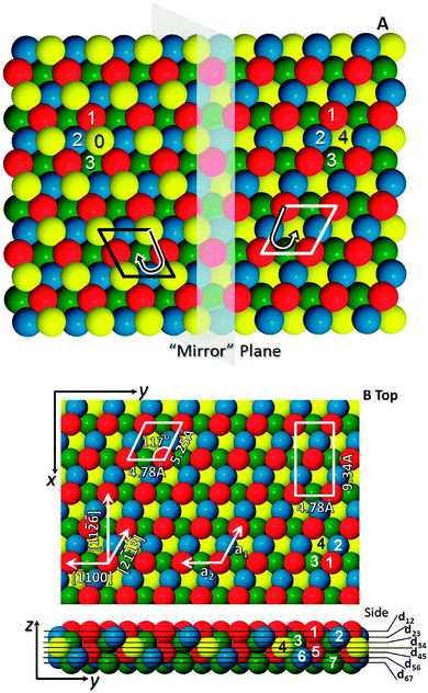 | ||
| Fig. 1 Representations of the chiral hcp (111) surface. (A) Shows the “mirror” plane which also defines a step edge in this image to show the two terraces with the l.h.s (the XDo termination) and the r.h.s (the XLo termination) differing in height by a monoatomic step. Atoms in each layer are numbered, and form a right or left handed descending spiral (B) shows top and side views of the XLo surface, in bulk positions, with crystallographic directions indicated by the arrows and the numbered atoms and interlayer spacings defined are as used in the LEED calculations. | ||
For ease of reference, the two terminations have been assigned labels XLo and XDo, according to the scheme introduced in ref. 7. A label beginning with the symbol X, in this scheme, indicates that this surface would display no chiral properties were it not for the presence of more than one atom within the bulk crystal's primitive unit cell. The presence of an additional symbol, L or D, indicates that each termination is designated either left- or right-handed, respectively (as determined by a well-defined, if essentially arbitrary, rule described in ref. 7). And finally, the subscript “o” is an indicator that the two terminations are necessarily degenerate.
With terraces larger or similar to the transfer width of the LEED experiment (∼100 Å, see STM data below), the LEED-IV data acquired at three different angles of incidence is an incoherent sum of the diffracted electron waves emerging from each terrace type as no spots are unique to a single terrace. Analysis was performed starting from the bulk crystal structure and it was assumed (and verified by STM) that both terraces were in equal abundance. The normal incidence data were used first to optimise the z-coordinates of the top eight layers and to trial a range of starting positions. The final structure was determined from the simultaneous fitting of the three angles of incidence data through optimisation of the x, y and z coordinates of the top six atomic layers and all polar and azimuthal incidence angles. This search yielded an RP of 0.263. The non-geometric parameters were then adjusted to achieve a better fit at this minimum resulting in RP of 0.260 ± 0.077. The uncertainty associated with each variable was determined by displacing each structural parameter (coordinates) from their minimum positions until the RP value changed by RR × RP,min while the other parameters were kept at constant. Typical experimental LEED-IV curves and their agreement with the calculated data are shown in Fig. 2; the best-fit atomic positions are shown in Table 1 for the XLo termination (the corresponding XDo coordinates being the mirror image of these across a plane perpendicular to the y axis).
 | ||
| Fig. 2 Sample LEED-IV curves used to calculate the structure of clean Re(111) with associated RP. The black curve represents the experimental data and the red curves are the theoretical fits. | ||
1) surface using simultaneous fit of three datasets taken at different incident angles (polar angles: 0°, +10°, −7°). The results show a large vertical contraction in the first interlayer spacing with a significant lateral displacement with respect to bulk positions in the top layer. All distances are measured in Å
| Layer (rms) | Bulk termination | Result from LEED-IV analysis | |||||||||
|---|---|---|---|---|---|---|---|---|---|---|---|
| X | Y | Z | X | Y | Z | ΔX | ΔY | ΔZ | d n,n+1 | Relaxation (%) | |
| 1 (0.11) | 0.000 | 0.000 | 0.000 | 0.006 (±0.11) | −0.166 (±0.13) | −0.247 (±0.05) | 0.006 (±0.11) | −0.166 (±0.13) | −0.247 (±0.05) | 0.449 (±0.05) | −32 (±10) |
| 2 (0.08) | −2.537 | 0.797 | −0.659 | −2.500 (±0.10) | 0.823 (±0.12) | −0.696 (±0.05) | 0.037 (±0.10) | 0.026 (±0.12) | −0.037 (±0.05) | 0.657 (±0.05) | 0 (±7) |
| 3 (0.04) | −0.409 | −2.391 | −1.319 | −0.344 (±0.11) | −2.379 (±0.10) | −1.353 (±0.04) | 0.064 (±0.11) | 0.012 (±0.10) | −0.034 (±0.04) | 0.589 (±0.04) | −11 (±6) |
| 4 (0.05) | −2.945 | −1.594 | −1.978 | −2.952 (±0.11) | −1.623 (±0.13) | −1.942 (±0.04) | −0.007 (±0.11) | −0.029 (±0.13) | 0.036 (±0.04) | 0.797 (±0.04) | 21 (±5) |
| 5 (0.06) | −0.817 | −4.782 | −2.637 | −0.787 (±0.09) | −4.793 (±0.11) | −2.739 (±0.05) | 0.030 (±0.09) | −0.011 (±0.11) | −0.102 (±0.05) | 0.581 (±0.05) | −12 (±9) |
| 6 (0.06) | −3.354 | −3.985 | −3.297 | −3.344 (±0.11) | −3.966 (±0.13) | −3.320 (±0.07) | 0.009 (±0.11) | 0.019 (±0.13) | −0.023 (±0.07) | 0.656 (±0.07) | 0 (±11) |
| 7 (0.06) | −1.226 | −7.173 | −3.956 | Fixed bulk | N/A | ||||||
| R P | 0.260 | ||||||||||
| RR | 0.077 | ||||||||||
| Energy range/eV | 5429.5 | ||||||||||
The results show that the first interlayer spacing is contracted very significantly, by 32% with respect to the bulk positions, whereas the second interlayer spacing is barely altered. The third interlayer spacing is contracted by 11% followed by a large expansion of the fourth interlayer spacing by 21%. The fifth interlayer spacing shows a 12% contraction. The displacements in the surface-normal direction are thus very similar to those found on the Pt(531) surface4,6 with a large contraction in the first interlayer spacing and a large expansion in the fourth (−33% and +43% respectively). The only other chiral metal surface structure determined to date, that of Cu(531),5 shows the same trends but with less dramatic magnitude.
In order to accommodate the large contraction of the first interlayer spacing, we find that the atoms in the top layer move considerable distances laterally (−0.166 ± 0.13 Å) towards the in-plane projection of the third-layer atom, while the second layer shifts a smaller amount in the opposite direction. The lateral relaxations effectively straighten the zig-zag row formed by the top two layers. In comparison with the only existing DFT calculation in the literature23 the overall contraction summed over the first two interlayer spacings is in good agreement. However, the individual values of the two interlayer spacings differ significantly. The DFT calculations in ref. 23 predict that the first interlayer spacing contracts by −15% and the second by −20%, versus −32 ± 10% and 0 ± 7% from LEED. Both experiment and DFT agree on a large expansion of the fourth interlayer spacing. In ref. 23 no lateral movements were reported, so we performed new detailed DFT calculations to fully consider the lateral movements of the atoms in the surface.
Our DFT results (for the 48-layer slab) are shown as displacements from bulk positions,24 alongside the experimental results, in Table 2. The r.m.s. distance between atomic coordinates of measured and calculated position in each layer are shown to facilitate discussion. Very good agreement is achieved for the pattern of movements of the atoms. In particular the lateral displacement of the top atom, −0.186 Å for theory vs. −0.166 Å for experiment agrees well within experimental error. The calculated interlayer relaxations in the surface-normal direction are d12 = −14%, d23 = −21%, d34 = −14%, d45 = +25%, d56 = −9%, d67 = −5%, d78 = +0% and d89 = +5%.‡ Thus, even when lateral displacements are considered, the calculations agree with those of Kaghazchi and Jacob23 in predicting a contraction of the second interlayer spacing that is significantly larger than found in experiment. A similar discrepancy occurs in the comparison between experiment and DFT for the Pt(531) surface, where the combined relaxations of the top two spacings agree well but are more evenly spread in DFT than experiment (in which the top interlayer spacing dominates the relaxation4). This is also apparent here, where the total contraction of the top two interlayer spacings is comparable between LEED and DFT, but the DFT results spread this evenly whereas in experiment it is concentrated in the first interlayer spacing. The origin of the discrepancy between DFT and LEED interlayer separation, which appears to be systematic, may well be a dynamic effect caused by thermal vibrations of the very open surface atoms, which is not included in the DFT calculations. Our optimal LEED fit has quite large r.m.s. displacements in the first and second layer atoms (0.11 Å and 0.08 Å respectively). Further work, for example conducting the experiment at low temperature, would be required to resolve this issue.
| Layer and distance/Å | ΔX/Å | ΔY/Å | ΔZ/Å | Δdn,n+1/% |
|---|---|---|---|---|
| 1 LEED | +0.006 | −0.166 | −0.247 | −32 |
| 1 DFT | −0.044 | −0.204 | −0.234 | −14 |
| LEED–DFT distance = 0.064 | ||||
| 2 LEED | +0.037 | +0.026 | −0.037 | 0 |
| 2 DFT | +0.093 | +0.060 | −0.145 | −21 |
| LEED–DFT distance = 0.126 | ||||
| 3 LEED | +0.064 | +0.012 | −0.034 | −11 |
| 3 DFT | +0.025 | +0.034 | +0.006 | −14 |
| LEED–DFT distance = 0.053 | ||||
| 4 LEED | −0.007 | −0.029 | +0.036 | +21 |
| 4 DFT | −0.040 | −0.021 | −0.085 | +25 |
| LEED–DFT distance = 0.060 | ||||
| 5 LEED | +0.030 | −0.011 | −0.102 | −12 |
| 5 DFT | +0.056 | −0.018 | −0.080 | −9 |
| LEED–DFT distance = 0.050 | ||||
| 6 LEED | +0.009 | +0.019 | −0.023 | 0 |
| 6 DFT | −0.046 | −0.002 | −0.024 | −5 |
| LEED–DFT distance = 0.043 | ||||
Overall, the atomic positions show remarkably good agreement, to within 0.07 Å, for all layers other than the second, which lends confidence to the finding of an unexpectedly large lateral displacement of the top most atoms.
STM
The STM images of the clean sample (Fig. 3) show very flat surfaces, with an r.m.s. roughness of just 0.65 Å, composed of irregular terraces separated by step edges that show no clearly preferred orientation. Atomic resolution STM imaging of the surface shows the atoms in each terrace with very low corrugation (Fig. 3b). The step heights between the terraces are measured to be ∼0.6–0.8 Å, which is consistent with one interlayer spacing. There are significant numbers of adatoms and small clusters of adatoms on the surface. The large number of step edges may be considered to arise due to the very low co-ordination of the outermost atoms. Atoms have the same coordination at step edges, within an island as part of a terrace or even as an adatom on the terrace so there are not expected to be large energy differences in the stabilities of these structures. | ||
| Fig. 3 STM images of the clean Re(111) surface. (a) (4000 Å × 4000 Å, 1.0 V bias 1 nA tunneling current) shows a large area image of a macroscopically flat surface. There are a large number of terraces in the image with no clearly preferred step directions. (b) (100 Å × 100 Å, 0.01 V bias 2 nA tunneling current) STM image at atomic resolution displaying the uppermost surface atoms of the unit cell. More than one terrace is visible, separated by ∼0.7 Å steps, with a centred rectangular motif. The differences in chirality due to lower atoms cannot be discriminated. | ||
In the presence of a low coverage of oxygen (either deliberately adsorbed or due to residual oxygen from incomplete cleaning, measured by XPS to be ∼0.2 ML or 3.6 × 10¹⁴ atoms cm−2) the flat morphology remains. In large area images such as Fig. 3a, the surface topography was found not to exceed 6 Å in height from the background plane. However, a global planar background subtraction is misleading, as Fig. 4a reveals. A local plane fit to an apparent terrace shows that the surface contains a multitude of short straight step edges running along the [2![[3 with combining macron]](https://www.rsc.org/images/entities/char_0033_0304.gif) ] direction which terminate abruptly. The height of these steps is on average around 3.38 Å which encompasses approximately 5 interlayer spacings. At first sight the short sections appear to be terminated by pairs of screw dislocations at either end. However on closer examination of the terraces, Fig. 4b, we see the different contrast in the highlighted region of the image due to terraces separated by irregular steps (∼0.7 Å high) which are difficult to discriminate at this scale. There are also shorter sections of step bunches that run in the [2] direction and join the other bunches to form pointed step structures.
] direction which terminate abruptly. The height of these steps is on average around 3.38 Å which encompasses approximately 5 interlayer spacings. At first sight the short sections appear to be terminated by pairs of screw dislocations at either end. However on closer examination of the terraces, Fig. 4b, we see the different contrast in the highlighted region of the image due to terraces separated by irregular steps (∼0.7 Å high) which are difficult to discriminate at this scale. There are also shorter sections of step bunches that run in the [2] direction and join the other bunches to form pointed step structures.
 | ||
| Fig. 4 Low coverage (∼0.2 ML) oxygen on the Re(111) surface. (a) Shows a large area image with short discontinuous segments across a macroscopically flat surface (2000 Å × 2000 Å, 0.01 V bias 2 nA tunneling current). (b) Is a medium resolution section in which subtle terraces can be seen in the boxed region (500 Å × 500 Å, 0.01 V bias 3 nA tunneling current). The apparent sharp step edges are in fact step bunches and have a height of several angstroms. | ||
By increasing the oxygen coverage on the surface we find that the length and frequency of occurrence of both the straight step-bunch segments and the step-bunches forming a point increases. A zig-zag step bunch morphology (see Fig. 5 at ∼1 ML or 1.8 × 10¹⁵ atoms cm−2) rapidly forms. The direction of the step bunches in the surface plane ([2] and [2]) is consistent with the formation of microfacets just a few atoms wide of the {100} family of planes. Interestingly, the [2] and [2] directions either run along or across the close packed rows defined by the top two atoms in the XLo and XDo terminated terraces. Thus the {100} family of microfacets may terminate at a terrace either along a row or at an oblique angle to these atomic rows. These different atomic configurations are not expected to be degenerate. Creating a microfacet furthermore requires the addition or removal of substrate atoms which, for the (111) surface, will change the terrace handedness if a single (or odd integer) number of layers is removed. Thus we expect the local terrace geometry to influence the initial stages of facet formation. This sensitivity is probably the cause of the complex step bunch morphology, with “pseudo” screw dislocation formation, and the reason most surface structures appear to be step bunches composed of multiple layers. Ultimately the fully facetted surface appears after extensive exposure to oxygen at elevated temperature and is reported to contain pyramids of (100), (010), (101) and (011) oriented facets.8,11,23,25
 | ||
| Fig. 5 The Re(111) surface with a medium oxygen coverage (20 L O2 adsorbed at 300 K vacuum annealed at 1000 K for 2 minutes, imaged at 1 V and 1 nA). The surface has now departed from planar and shows an ordered array of microfacets which is a precursor to the fully facetted surfaces. The measured oxygen coverage is approximately 1 ML, 1.8 × 10¹⁵ atoms cm−2. | ||
Thus we conclude that the step-bunches are caused by oxygen adsorption and that the step bunching is the pre-cursor to a micro-facetted surface matching that observed in ref. 25. While the intersection of the microfacets and surface now lead to a clearly zig-zag surface morphology the surface also shows bands of step edges and terraces running approximately parallel to [100]. More prolonged exposure drives the surface into the thermodynamically stable fully facetted regime.
Surface energy and stress
To investigate how one might lift the degeneracy of the two chiral surface terminations, we have used first-principles calculations to assess the surface energy and surface stress components. Values of the total supercell energy per unit cross-sectional area and in-plane two-dimensional stress are listed in Table 3. These quantities include surface contributions from either side of the slab, together with bulk contributions that should be linear in the number of layers. Extrapolating back to a hypothetical slab thickness of zero, and dividing the result by two, therefore allows us to extract the contribution from each surface of the slab. The surface energy is then found to be 215 meV Å−2 (3.45 J m−2), in excellent agreement with the value of 220 meV Å−2 (3.53 J m−2) quoted by Kaghazchi and Jacob,23 while the surface stress components are σxx = 342.38 meV Å−2, σxy = −46.93 meV Å−2 and σyy = 102.76 meV Å−2 for the XLo surface termination; the sign of σyy is simply reversed for the XDo termination.| Number of layers | Energy/area | σ xx | σ xy | σ yy |
|---|---|---|---|---|
| 36 | −4011.08 | 498.11 | −67.62 | 55.59 |
| 38 | −4233.94 | 494.75 | −69.24 | 69.24 |
| 40 | −4456.85 | 492.88 | −62.38 | 83.13 |
| 42 | −4679.67 | 458.29 | −52.97 | 47.18 |
| 44 | −4903.53 | 450.44 | −56.65 | 41.69 |
| 46 | −5125.39 | 453.31 | −56.65 | 30.66 |
| 48 | −5348.25 | 444.64 | −63.44 | 26.49 |
Diagonalising the surface stress tensor, we obtain normal stress eigenvalues of 93.90 meV Å−2 and 351.24 meV Å−2, directed 11° clockwise (anticlockwise) from the [100] and [11![[6 with combining macron]](https://www.rsc.org/images/entities/char_0036_0304.gif) ] directions for the XLo (XDo) termination. For reference, the [2] and [2] directions run approximately 27° clockwise and anticlockwise from the [11] direction, respectively. The normal stress ellipses corresponding to these parameters are shown in Fig. 6, which emphasises the fact that the stress tensor of a chiral surface termination is not tied to any particular crystallographic axes (cf. the surface stress ellipses calculated previously for a family of chiral bcc surfaces26). For comparison, the isotropic surface stress of Re(0001) has previously been calculated as 212 meV Å−2, while the anisotropic stress of Re(100) was calculated to have eigenvalues 221 meV Å−2 and 309 meV Å−2 along and across its close-packed atomic rows respectively.27
] directions for the XLo (XDo) termination. For reference, the [2] and [2] directions run approximately 27° clockwise and anticlockwise from the [11] direction, respectively. The normal stress ellipses corresponding to these parameters are shown in Fig. 6, which emphasises the fact that the stress tensor of a chiral surface termination is not tied to any particular crystallographic axes (cf. the surface stress ellipses calculated previously for a family of chiral bcc surfaces26). For comparison, the isotropic surface stress of Re(0001) has previously been calculated as 212 meV Å−2, while the anisotropic stress of Re(100) was calculated to have eigenvalues 221 meV Å−2 and 309 meV Å−2 along and across its close-packed atomic rows respectively.27
 | ||
| Fig. 6 Normal surface stress ellipses for the XLo and XDo terminations (left and right panels, respectively). The radius of the ellipse in any particular azimuth is proportional to the normal surface stress in that direction. The central panel shows the normal stress ellipses superposed, with the directions of maximum normal stress difference between the two terminations marked. | ||
Now, these parameters imply that the normal stress difference between the XLo and XDo terminations is maximised along axes running at 15° from the [11] direction. For an axis running 15° clockwise from [11], the XLo termination will have a normal tensile stress of 341.63 meV Å−2, while the same property for the XDo termination will take a value of just 188.80 meV Å−2, the situation being reversed along an axis running 15° anticlockwise from [11]. In either case, the normal stress difference amounts to 152.83 meV Å−2.
To determine whether this stress difference is of any practical significance, we note that, to first order, the energy difference that develops between the two enantiomeric terminations under the application of a uniaxial normal surface strain will simply equal the difference between their surface stresses along the axis of strain, multiplied by the fractional strain. A 1% tensile strain directed along an axis 15° clockwise from the [11] direction would therefore generate an energy difference of 0.0015 meV Å−2 in favour of the XDo termination, with the reverse being true for a strain directed 15° anticlockwise from [11]. For reference, the calculated surface energy difference favouring the missing row (1 × 2) reconstruction on the Pt(311) surface also amounts to just 0.0015 meV Å−2, and yet this is distinctly favoured over the (1 × 1) phase in experiments. It therefore seems likely that a modest strain, amounting to just a few percent, may well be able to drive this surface towards a single chiral termination. Varying the direction of this strain would allow the chirality to be swapped at will, albeit possibly subject to simultaneous annealing.
Summary and conclusion
The experimental LEED and STM results confirm that this surface is globally racemic: that is, terminated by two chiral terrace structures that are stereoisomers and degenerate in energy. The surface atoms in each chiral hcp terrace are found to relax in a similar pattern to the chiral fcc(531) Pt and Cu surfaces (which are uniterminated) with a large 32% contraction of the first interlayer spacing, negligible changes in the second interlayer spacing, an 11% contraction of the third interlayer spacing, followed by a large expansion of the fourth by 21%. The top-layer atoms also move laterally to a substantial degree. The quantitative LEED structure results are supported by DFT calculations with excellent agreement apart from the second layer. The clean surface is surprisingly flat and has a very low r.m.s. roughness. The surface does, however, display a multitude of small terraces. Adsorption of oxygen, and other small adsorbates, is well known to induce faceting of this surface. We have shown that the earliest stage of oxygen adsorption leads to step bunching, re-organisation of the terrace structure and the establishment of {100} microfacets that decorate the surface giving the appearance of short stepped sections running in the [2] direction. Increasing the surface coverage of O atoms extends the length of the step bunches and allows new [2] directed segments to grow which eventually lead to the partially facetted surfaces seen in previous work.
While adsorption at elevated temperature leads to large-scale mass transport and faceting, one can envisage at lower temperatures that mass transport of surface Re atoms is facile due to their low coordination on this surface. The two chiral surface terminations are interchangeable through the addition or subtraction of just the uppermost atoms. We suggest that by inducing a bias stabilising one chiral termination over the other, for example through the adsorption of a low coverage of chiral modifiers or application of a magnetic or strain field, it may be possible to induce one set of the uppermost atoms in an unfavourable terrace to migrate to form adatom and vacancy islands on that terrace. Adatom and vacancy islands on an unfavourable terrace will have the opposite (and more favourable) chirality separated by double height step edges. The result would be the creation of a switchable homochiral surface structure built from a racemic crystal, which may be able to controllably direct stereochemical reactions. Our calculations indicate that even a modest strain can lift the degeneracy between terraces of opposing chirality by an amount consistent with the possibility of surface reconstruction. In this work, we have shown that step edges can readily be bunched by adsorbates, and future work will look at inducing bias in chiral surface termination and the stabilisation of even-numbered step bunches.
Acknowledgements
The authors would like to thank the Royal Society/Wolfson foundation for refurbished laboratory space and HAE would like to thank the EPSRC for a PhD studentship.References
- Z. W. Wang and R. E. Palmer, Nano Lett., 2012, 12, 5510 CrossRef CAS PubMed.
- A. Tadich, J. Riley, L. Thomsen, B. C. C. Cowie and M. J. Gladys, Phys. Rev. Lett., 2011, 107, 175501 CrossRef CAS.
- T. Mallat, E. Orglmeister and A. Baiker, Chem. Rev., 2007, 107, 4863 CrossRef CAS PubMed.
- S. R. Puisto, G. Held, V. Ranea, S. J. Jenkins, E. E. Mola and D. A. King, J. Phys. Chem. B, 2005, 109, 22456 CrossRef CAS PubMed.
- G. Jones, M. J. Gladys, J. Ottal, S. J. Jenkins and G. Held, Phys. Rev. B: Condens. Matter Mater. Phys., 2009, 79, 165420 CrossRef.
- S. R. Puisto, G. Held and D. A. King, Phys. Rev. Lett., 2005, 95, 036102 CrossRef CAS.
- S. J. Jenkins and S. J. Pratt, Surf. Sci. Rep., 2007, 62, 373 CrossRef CAS PubMed.
- H. Wang, PhD thesis, Rutgers University, 2008.
- P. Kaghazchi, T. Jacob, H. Wang, W. Chen and T. E. Madey, Phys. Rev. B: Condens. Matter Mater. Phys., 2009, 79, 132107 CrossRef.
- T. E. Madey, W. H. Chen, H. Wang, P. Kaghazchi and T. Jacob, Chem. Soc. Rev., 2008, 37, 2310 RSC.
- X. Yang, B. E. Koel, H. Wang, W. Chen and R. Bartynski, ACS Nano, 2012, 6, 1404 CrossRef CAS PubMed.
- H. A. Etman, Z. V. Zheleva, G. Held and R. A. Bennett, J. Phys. Chem. C, 2011, 115, 4191 CAS.
- R. A. Bennett, J. S. Mulley, H. A. Etman, A. Sparkes, T. Eralp, G. Held, S. A. Cavill and S. S. Dhesi, Phys. Rev. B: Condens. Matter Mater. Phys., 2012, 86, 045454 CrossRef.
- http://www.reading.ac.uk/web/FILES/chemistry/Georg_Held_LEED_Description.pdf .
- G. Held and W. Braun, CLEED manual, available from the authors.
- M. A. Van Hove, W. H. Weinberg and C. M. Chan, Low Energy Electron Diffraction, Springer, New York, 1986 Search PubMed.
- J. B. Pendry, Low Energy Electron Diffraction, Academic Press, London, 1974 Search PubMed.
- J. B. Pendry, J. Phys. C, 1980, 13, 937 CrossRef CAS.
- S. J. Clark, M. D. Segall, C. J. Pickard, P. J. Hasnip, M. J. Probert, K. Refson and M. C. Payne, Z. Kristallogr., 2005, 220, 567 CrossRef CAS.
- D. Vanderbilt, Phys. Rev. B: Condens. Matter Mater. Phys., 1990, 41, 7892 CrossRef.
- J. P. Perdew, J. A. Chevary, S. H. Vosko, K. A. Jackson, M. R. Pederson, D. J. Singh and C. Fiolhais, Phys. Rev. B: Condens. Matter Mater. Phys., 1992, 46, 6671 CrossRef CAS.
- H. J. Monkhorst and J. D. Pack, Phys. Rev. B: Solid State, 1976, 13, 5188 CrossRef.
- P. Kaghazchi and T. Jacob, Phys. Rev. B: Condens. Matter Mater. Phys., 2010, 82, 165448 CrossRef.
- We have rigidly shifted the raw DFT structure by (0.030, 0.020, −0.022) Å to minimise the r.m.s. distance between atomic positions obtained by LEED and DFT.
- P. Kaghazchi, D. Fantauzzi, J. Anton and T. Jacob, Phys. Chem. Chem. Phys., 2010, 12, 8669 RSC.
- M. Blanco-Rey, S. J. Pratt and S. J. Jenkins, Phys. Rev. Lett., 2009, 102, 026102 CrossRef CAS.
- M. Blanco-Rey and S. J. Jenkins, J. Phys.: Condens. Matter, 2010, 22, 135007 CrossRef CAS PubMed.
Footnotes |
| † Electronic supplementary information (ESI) available. See DOI: 10.1039/c3cp53165a |
| ‡ Test calculations within the local density approximation (LDA) gave almost identical interlayer relaxations of d12 = −16%, d23 = −22%, d34 = −15%, d45 = +24%, d56 = −7%, d67 = −3%, d78 = −0% and d89 = +3%, giving us confidence that our results are not very sensitive to the particular choice of functional that we made. |
| This journal is © the Owner Societies 2013 |