 Open Access Article
 This Open Access Article is licensed under a
 Creative Commons Attribution 3.0 Unported Licence
Atmospheric pressure chemical vapour deposition of boron doped titanium dioxide for photocatalytic water reduction and oxidation†
Penelope Carmichaela,
David Hazafyb,
Davinder S. Bhachua,
Andrew Millsb,
Jawwad A. Darra and
Ivan P. Parkin*a
aDepartment of Chemistry, University College London, 20 Gordon Street, London, WC1H 0AJ, UK. E-mail: i.p.parkin@ucl.ac.uk; Fax: +44 (0)20 7697463; Tel: +44 (0)20 76794669
bSchool of Chemistry and Chemical Engineering, Queen's University Belfast, Stranmillis Road, Belfast BT9 5AG, UK
First published on 22nd August 2013
Abstract
Boron-doped titanium dioxide (B-TiO2) films were deposited by atmospheric pressure chemical vapour deposition of titanium(IV) chloride, ethyl acetate and tri-isopropyl borate on steel and fluorine-doped-tin oxide substrates at 500, 550 and 600 °C, respectively. The films were characterised using powder X-ray diffraction (PXRD), which showed anatase phase TiO2 at lower deposition temperatures (500 and 550 °C) and rutile at higher deposition temperatures (600 °C). X-ray photoelectron spectroscopy (XPS) showed a dopant level of 0.9 at% B in an O-substitutional position. The ability of the films to reduce water was tested in a sacrificial system using 365 nm UV light with an irradiance of 2 mW cm−2. Hydrogen production rates of B-TiO2 at 24 μL cm−2 h−1 far exceeded undoped TiO2 at 2.6 μL cm−2 h−1. The B-TiO2 samples were also shown to be active for water oxidation in a sacrificial solution. Photocurrent density tests also revealed that B-doped samples performed better, with an earlier onset of photocurrent.
Introduction
The past five years have seen a greater than two-fold increase in global investment in clean energy with the fastest growing area in the renewable energy industry being solar photovoltaics (PV).1 Despite the ubiquity of PV in the solar industry, costly energy storage solutions are required. A more practical and potentially cheaper option is to take inspiration from nature and directly convert solar energy into a chemical fuel (such as hydrogen), which can be stored and then used as required. Since Honda and Fujishima's discovery of biased photochemical water-splitting using titanium dioxide,2 this material has become the most intensely investigated photocatalyst, owing in large part to its low cost, high activity and remarkable stability. Due to the large band gap of TiO2 (3.2 eV for anatase) and thus its absorption solely in the UV region, a number of doping studies have been conducted in order to facilitate visible light absorption and increase the efficiency of solar harvesting.3,4 In particular non-metallic elements have been shown to be promising dopants,5–9 enhancing visible light absorption but not suffering from charge-carrier recombination as is often the case with metal dopants.10Boron is an attractive candidate as dopant in TiO2 as not only have there have been reports on powder samples that show visible light photocatalysis,11,12 but also of improved UV activity.13 Here we report the facile synthesis of boron doped titania (B-TiO2) films using atmospheric pressure chemical vapour deposition (APCVD) onto steel substrates, which could easily be scaled to a reel-to-reel process.14 Titanium dioxide coatings on steel offer the potential to act part of a water splitting photodiode. In a photodiode water can be reduced to hydrogen on the reverse side relative to illumination by means of an additional hydrogen catalyst (such as platinum) and oxidised on the front face by the photocatalyst (which can be coupled with an oxidation co-catalyst).15,16 Due to a potential difference, electrons and holes generated in the photocatalyst are vectorially separated; holes remain in the photocatalyst and electrons can travel through the metal substrate to the hydrogen catalyst on the reverse (Fig. 1). The photodiode can be sandwiched between two water containing sources and oxygen and hydrogen are generated in spatially remote compartments avoiding the need for a costly downstream separation step. Herein, the authors show that incorporation of boron into the TiO2 lattice changes the morphology and orientation of the crystallites and significantly increases the rate of sacrificial hydrogen production.
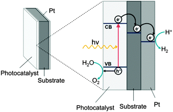 | ||
| Fig. 1 Schematic of a photodiode for water oxidation and reduction, showing band structure (not absolute band energies) and vectorial separation of holes and electrons. | ||
Experimental procedure
Preparation of photodiode
Thin films of boron doped TiO2 were synthesised in a custom-built cold walled CVD reactor using APCVD. The reaction chamber consisted of a quartz tube 330 mm in length and 105 mm in diameter and contained a graphite reactor bed, heated by three Whatman cartridges inserted into the block. Films were deposited onto isopropanol cleaned 304 grade steel substrates of area 25 × 25 mm2 which had been placed on Pilkington float glass of dimension 220 × 85 mm2 and fluorine-doped-tin oxide (FTO) subtrates (Pilkington) of area 25 × 25 mm2 which were placed directly on the graphite block. Titanium(IV) chloride (Aldrich, 99.9%), ethyl acetate (Fischer, reagent grade) and triisopropyl borate (Aldrich, 99.9%) were used as precursors and were located in heated bubblers at 70, 40 and 75 °C respectively. Nitrogen (BOC, 99%) was used as a carrier gas in order to transport the precursors through heated lines, all with a flow rate of 0.5 L min−1. Titanium(IV) chloride and ethyl acetate were introduced into one mixing chamber and triisopropyl borate into a second with additional nitrogen flow rates of 4.8 and 1.6 L min−1, respectively. The mixing chambers were held at 250 °C to avoid condensation of precursors. The two gas flows were then passed through a 2.5 cm baffle manifold into the reaction chamber. Depositions were carried out at 500, 550 and 600 °C for 30 s to 3 min. Platinum was then coated onto the reverse side of the substrates in an argon atmosphere using an EMScope SC500 sputter coater at a pressure of 0.1 Torr and current of 35 μA for 4 min.Characterisation and analysis
To confirm the phase of titania formed, powder X-ray diffraction (PXRD) and Raman spectroscopy were used. PXRD of steel coupons was performed using a Bruker D4 Bragg–Brentano theta-2 theta reflection geometry machine equipped with Cu Kα1+2 source powered at 40 kV, 30 mA coupled with a post-sample graphite monochromator and scintillation counter detector. PXRD of films on glass was carried out using a Bruker D8 diffractometer with parallel beam and grazing incidence angle optics equipped with Cu Kα1+2 source powered at 40 kV, 40 mA and coupled with a LynxEye silicon strip detector. In both cases scans were performed with a 0.05° step for 2 s per step and 0.5 slits and for analysis of films on glass a 0.5° incidence angle was used.Raman spectroscopy was conducted using a Renishaw in Via spectrometer equipped with a 532 nm wavelength laser. X-ray photoelectron spectroscopy (XPS) was used to determine the composition of the films and spectra were recorded on a Kratos Axis Nova spectrometer equipped with a monochromated Al Kα X-ray source and delay line detector. Survey spectra were recorded with energy of 160 eV and higher resolution spectra were recorded at 80 eV.
A Filmetrics F20 single spot thin film machine was used to analyse the thicknesses of the samples. Scanning electron microscopy (SEM) was used to observe surface morphology of the films and was carried out using a JEOL 6301 SEM with secondary electron imaging and accelerating voltage of 5 kV.
The ability of the films to produce hydrogen was tested in 50 mL of a stirred sacrificial solution of 1![[thin space (1/6-em)]](https://www.rsc.org/images/entities/char_2009.gif) :1 0.2 M HCl:absolute ethanol. The ethanol was used as a hole scavenger and the remaining photogenerated electrons performed the reduction reaction. A pH bias was used in order to shift the band position of the titania, a well-known phenomenon.17 The samples were suspended from a rubber septum in a sealed glass vessel equipped with a water cooled jacket and which was filled with 50 mL of sacrificial solution leaving a headspace of 15 mL. They were then irradiated with two 8 W Vilber 365 nm black light lamps and 250 μL of gas was collected from the headspace every 15 minutes for two hours and analysed using gas chromatography. In order to quantify the amount of hydrogen present, the counts were compared to a sample of pure hydrogen.
:1 0.2 M HCl:absolute ethanol. The ethanol was used as a hole scavenger and the remaining photogenerated electrons performed the reduction reaction. A pH bias was used in order to shift the band position of the titania, a well-known phenomenon.17 The samples were suspended from a rubber septum in a sealed glass vessel equipped with a water cooled jacket and which was filled with 50 mL of sacrificial solution leaving a headspace of 15 mL. They were then irradiated with two 8 W Vilber 365 nm black light lamps and 250 μL of gas was collected from the headspace every 15 minutes for two hours and analysed using gas chromatography. In order to quantify the amount of hydrogen present, the counts were compared to a sample of pure hydrogen.
Oxygen evolution testing was carried out in a sacrificial electron acceptor solution consisting of aqueous solutions of 20 mL of 0.2 M NaOH and 20 mL of 0.02 M Na2S2O8. The solution was placed in a gas tight round glass reactor attached to an oxygen electrode (Rank Brothers), under constant stirring. The oxygen concentration in the aqueous phase was measured as an oxygen reducing electrical current using a potentiostat. The photodiode was then immersed into the solution, purged with argon and then re-purged before each irradiation cycle. The sample was irradiated for a set time interval using a 150 W xenon arc lamp equipped with filters (WG 320 and UG5 filters), simulating a UV solar output, with a UVA irradiance of 15 mW cm−2. The irradiation was repeated three times for every sample.
The photocurrent density generated by samples was recorded using a Metrohm Autolab potentiostat. Samples were placed in a three electrode glass cell using an Ag/AgNO3 reference electrode (via a Luggin capillary), Pt wire counter electrode (area ca. 1.6 cm2) and working electrode (area ca. 3.2 cm2). An aqueous 0.1 M KNO3 was used as an electrolyte (pH ca. 5.5). The potential range (usually −0.8 to 1.0 V) was scanned at 50 mV s−1 and three cycles were completed; the first two with light being chopped and the last one with light on (note: sample was always in dark when the potential was swept in the negative direction). A 200 W xenon arc lamp was used to illuminate the sample. UG320 and UG5 band-pass filters were used to simulate the sun's UV profile with an irradiance of 10 mW cm−2.
Results and discussion
Structural characterisation
Titanium dioxide and boron doped TiO2 films were deposited onto steel substrates at 500, 550 and 600 °C, with thicknesses between 200–1500 nm. The films were crack-free and well adhered, with no evidence of delamination on application of the Scotch tape test. The thinner films were deposited for functional testing as it has been shown that 200 nm is an optimum thickness for the TiO2 photocatalyst in a water-splitting diode.16 The thickest films were selected for detailed powder X-ray diffraction studies, which revealed crystalline material; films deposited at 500 and 550 °C corresponded to anatase, as observed previously,18 and those deposited at 600 °C were rutile, TiO2 (Fig. 2a).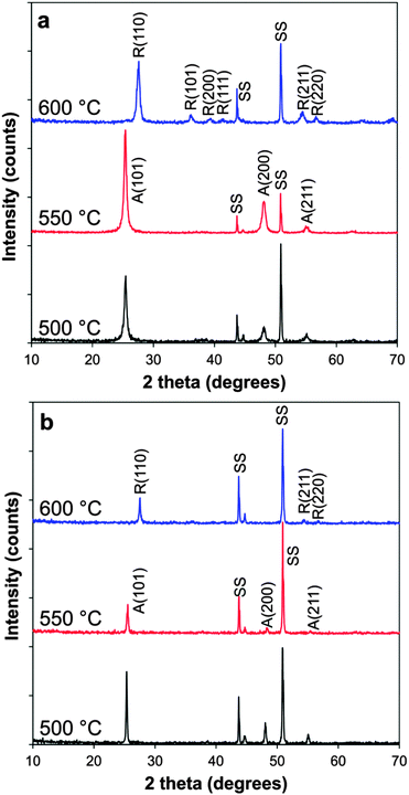 | ||
| Fig. 2 XRD patterns of (a) B-doped TiO2 films and (b) non-doped TiO2 deposited at varying temperatures. A = anatase; R = rutile; SS = stainless steel substrate. | ||
No additional phases were observed in any spectra, (and in particular no crystalline B2O3), indicating any boron present is incorporated into the TiO2 lattice, is an amorphous form or is below the detection limit. Diffraction patterns were also taken of the thinner films and were found to contain the same phases and relative intensities though were generally poorer quality due to higher background signal from the steel substrate.
SEM showed that upon B-doping of the TiO2 films there was a marked change in the morphology of the particles. The non-doped samples were composed of densely packed, highly faceted particles of typical size around 100 nm, whereas the doped samples were elongated and blade-like, of typical size around 400 nm, (Fig. 3). The crystallite size was estimated from the broadening of the anatase (101) peak and the rutile (110) peak using the Scherrer equation (Table 1) and it was observed that smaller crystallites are obtained when the TiO2 films were doped with boron, a phenomenon which has been reported previously in powder samples.13 Interestingly with increasing deposition temperature the crystallite size actually decreased, which may indicate higher rates of nucleation during the CVD process.
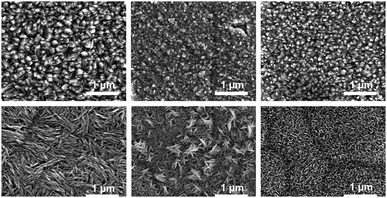 | ||
| Fig. 3 SEM images of non-doped (top row) and boron doped (bottom row) TiO2 CVD samples made at 500, 550 and 600 °C left to right. | ||
| Sample | Reflection TC (hkl) | Crystallite size (nm) | Lattice parameter (Å) | |||||||
|---|---|---|---|---|---|---|---|---|---|---|
| A(101) | A(200) | A(211) | R(110) | R(200) | R(211) | R(220) | a-axis | c-axis | ||
| TiO2 500 °C | 1.1 | 0.9 | — | — | — | — | — | 66 | 3.7867(3) | 9.5068(57) |
| TiO2 550 °C | 1.1 | 0.6 | — | — | — | — | — | 31 | 3.7820(3) | 9.61002(52) |
| TiO2 600 °C | — | — | — | 1.7 | — | 0.3 | 4.8 | 51 | — | — |
| B-TiO2 500 °C | 1.4 | 1.0 | 0.4 | — | — | — | — | 20 | 3.7871(4) | 9.48438(69) |
| B-TiO2 550 °C | 1.4 | 1.5 | 0.4 | — | — | — | — | 18 | 3.7826(24) | 9.473(12) |
| B-TiO2 600 °C | — | — | — | 2.7 | 1.8 | 1.2 | 1.3 | 14 | — | — |
Lattice parameters for the B-doped and undoped systems were calculated using the general structure analysis system (GSAS), where the patterns were fit employing a Le Bail model. For fitting ease and accuracy, PXRD patterns were obtained of films on the underlying glass substrates so no contributions from the steel substrates were present. For the anatase B-doped films deposited at 500 and 550 °C the lattice parameter along the c-axis decreased by 0.02 and 0.137 Å respectively (Table 1), as compared to the undoped films and 0.03 and 0.04 Å as compared to reference values (44882-ICSD). Lattice parameters were not calculated for the films deposited at 600 °C as the films on glass were found to be anatase, a directing effect which has been observed previously.15 The orientation of crystallites in TiO2 is known to affect the material's properties, such as wettability,19 as well as photocatalytic activity.20–22 The crystallite orientations of the B-doped and undoped TiO2 films were semi-quantitatively evaluated by calculating the texture coefficient through comparison of the relative peak intensities with anatase and rutile powder diffraction standards (anatase: 44882-ICSD, rutile: 44881-ICSD). Those reflections in which enhanced or suppressed orientation were identified are outlined in Table 1. It was observed that for anatase phase TiO2 in both doped and non-doped samples the most intense reflection was the (101) plane which is known to be the most thermodynamically stable and prevalent in nanocrystalline TiO2,23 and that the degree of orientation in the (101) plane was greater in the boron doped samples. Interestingly, growth in the remaining crystal planes was suppressed in all samples with the exception of the boron doped samples, where the (200) plane had a 50% increased orientation when the film was deposited at 550 °C. The average surface energies of the different crystal faces in anatase have been shown to follow the order: {110} at 1.09 J m−2 > {001} at 0.9 J m−2 > {100} at 0.53 J m−2 > {101} at 0.44 J m−2,24,25 and so the growth of thin films with increased orientation of higher energy facets is highly desirable. In the rutile sample increased orientation in the (110) plane was observed in the doped and undoped samples but this was greater with the boron dopant present. In the undoped rutile sample, all other crystal faces were suppressed whereas in the doped sample the (200), (211) and (220) all had increased texturing. For rutile, the {110} has been shown to be the most active reduction site for catalysis and so this is likely to enhance the material's catalytic ability.26
Raman spectroscopy was used to probe the chemical environment of the atoms in the film as it is very sensitive to local crystallinity and microstructures of a material. The characteristic Raman peaks of anatase TiO2 lie at 144, 396, 516 and 639 cm−1 and can be assigned to the Eg, B1g, A1g or B1g, and Eg modes, respectively.27 The main rutile peaks lie at 144, 447 and 609 cm−1 and can be assigned to the B1g, A1g and Eg modes, respectively. A peak also is present at ∼232 cm−1 and is caused by a multi-phonon scattering process.28
The Raman spectra showed a phase transformation from anatase at lower deposition temperature, (500 and 550 °C) to rutile at higher temperatures (600 °C), agreeing with the XRD data. Crucially in the doped samples, a shift in the anatase Eg band is observable, from 145.6 cm−1 in undoped TiO2 to 151.3 cm−1 for both doped samples (Fig. 4a). A blue shift in the anatase Eg peak has been attributed to phonon confinement and oxygen deficiencies.29–31 Phonon confinement can be caused by several factors, including an expansion in the unit cell volume caused by the introduction of a dopant. An example of this is in W-doped TiO2, where a direct correlation was drawn between W concentration and the extent of the Eg shift.29 Another mechanism by which phonon confinement is reported to occur is through a reduction in particle size.32,33 In the case of the results presented here, a combination of the presence of a dopant, as well as a decrease in particle size compared to non-doped TiO2 is likely to account for the large blue shift.
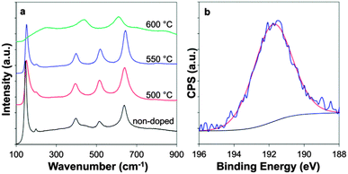 | ||
| Fig. 4 (a) Raman spectra of B-TiO2 at varying temperature and (b) XPS spectra of B-doped TiO2 deposited at 550 °C. | ||
The samples were analysed using XPS to determine the boron content as well as the chemical environment of the doped species. There have been many discrepancies in the literature regarding the chemical environment of boron doped into powder TiO2 samples. The characteristic peaks of cationic B in B2O3 and anionic B in TiB2 lie at 193.1 and 187.5 eV respectively.34,35 Typically intermediate values are observed for B-TiO2. Generally peaks at ∼190–191 eV have been attributed to boron in an oxygen substitutional position,11,36,37 and peaks in the range ∼191–192 eV to interstitial boron.37,38
XPS was carried out on ten different B-doped CVD samples and it was found that the Ti peak was located at an average chemical shift of 459.2 ± 0.1 eV, indicative of Ti4+ with no reduced Ti3+ species (ESI 1†).39 The O 1s peak was located at 530.4 ± 0.2 eV (ESI 2†). The B 1s peak was observed at an average chemical shift of 191.4 ± 0.2 eV, which combined with the contraction in the c-axis of the unit cell observed from the PXRD data (Table 1) is likely attributable to boron in substitutional position.36 The position of the peak did not vary with phase (anatase vs. rutile) and the average dopant level was found to be 0.9 ± 0.3 at%, Fig. 4b sample deposited at 550 °C, (see ESI 3† for samples deposited at 500 and 600 °C).
Photocatalytic water reduction and oxidation
The ability of the films to produce hydrogen was tested in sealed vessel containing a sacrificial solution. Samples were irradiated using 365 nm UV light of irradiance 2 mW cm−2. Samples of thickness ∼200 nm were selected for testing, as this has been demonstrated to be an optimum thickness for water reduction using a TiO2 photodiode.16 The gas produced was analysed using gas chromatography and in all samples, a steady rate of hydrogen production was observed (Fig. 5b). No H2 production was observed when the samples were held in the dark, indicating that the reaction was a photocatalytic and not a chemical one.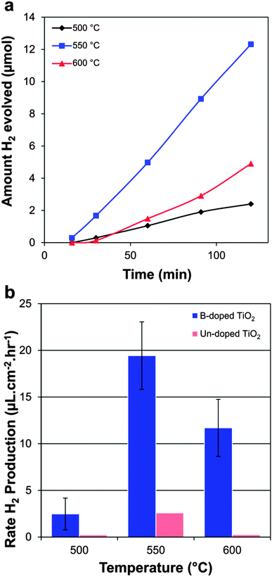 | ||
| Fig. 5 Photocatalytic production of hydrogen by boron doped and undoped samples; (a) moles of hydrogen in the headspace with time of B-TiO2 deposited at varying temperature and (b) average hydrogen production rates of doped and non-doped samples. | ||
Four different doped samples deposited at each temperature were tested, from which an average hydrogen production rate was calculated (Fig. 5a). The sample with the highest hydrogen production rate was tested again for 4 hours and a similar rate of hydrogen production was observed (ESI 4†) indicating the films are stable during use. Samples deposited at 550 °C generally gave the highest hydrogen production rates and doped samples far outperformed their undoped counterparts, with activities an order of magnitude higher. The best B-doped sample gave a hydrogen production rate of 24 μL cm−2 h−1, as compared to the best non doped sample which gave a rate of 2.6 μL cm−2 h−1. The B-doped samples also surpassed similar systems in the literature, where undoped TiO2 photodiode and undoped Pt- loaded TiO2 thin film systems gave hydrogen production rates of 3 and 7 μL cm−2 h−1 respectively.16,40 It is likely that the enhancement in rate is due not only to the presence of the boron dopant (which is known to improve UV activity of certain photocatalysts,13) but also due to the enhanced orientation along the (200) face observed in the samples deposited at 550 °C, which saw a 50% increase as compared to powder diffraction standards (Table 1). The {100} plane is a high energy face in anatase and its abundance has been shown to increase the rate of photocatalysis.41,42 If the enhancement in rate were due the presence of B alone, higher rates would be expected from samples deposited at 500 °C, which are also anatase containing a similar %B content, but average orientation on the (200) face.
Visible light harvesting was enhanced by the B-dopant (ESI 6†) and so the visible light activity of the samples was assessed by irradiation in sacrificial solution with light λ > 400 nm for 4 h, but no hydrogen was detected. As a result it is thought that the use of a co-dopant such as nitrogen may be necessary to facilitate visible light photocatalysis, as observed by other authors.43
The best performing boron doped samples were tested for their water oxidation capabilities in a sacrificial solution using UVA illumination of irradiance 15 mW cm−2. The degassed vessel containing the sample was sealed and left for a period of time before the light was turned on to ensure any oxygen observed was from the sample and not due to leaks (ESI 5a and b†). The sample deposited at 500 °C was inactive for oxygen production and the samples deposited at 550 and 600 °C gave oxygen evolution rates of 6.6 and 22.0 μL cm−2 h−1 respectively. Interestingly the rutile sample deposited at 600 °C performed better than the anatase sample deposited at 550 °C in the water oxidation test, but worse in the water reduction test. The relative poor performance of the anatase samples for water oxidation could be accounted for by the suppression of the {001} face, which has been shown to be the anatase oxidation site.26 In order to improve the activity of the anatase samples for water photooxidation a co-catalyst could be used.44,45
UV light sources of different irradiances were used for the hydrogen and oxygen evolution tests (2 and 15 mW cm−2 respectively) and so in order to compare the results apparent quantum yields were calculated using the formula: AQY (%) = (number of reacted electrons or holes)/(number of incident photons) × 100.46 The B-TiO2 sample deposited at 550 °C gave better hydrogen production but the sample deposited at 600 °C gave stoichiometric AQYs of hydrogen and oxygen (Table 2).
| Sample | AQY hydrogen production (%) | AQY oxygen production (%) |
|---|---|---|
| B-TiO2 500 | 1.0 | 0.0 |
| B-TiO2 550 | 8.1 | 0.7 |
| B-TiO2 600 | 4.9 | 2.4 |
The photocurrent density as a function of applied voltage produced by the samples deposited on FTO was assessed using filters to simulate the sun's UV content and is presented in Fig. 6a and b. The light was chopped during the positive sweep, showing that any current produced was indeed photocurrent and not caused by photocorrosion and the sample was held in the dark on the negative sweep showing that the dark current is negligible. The B-TiO2 samples showed a 0.5 V smaller overpotential against water photo-oxidation (more rapid onset of current) than the non-doped samples and a steep profile before reaching a plateau which is typical of an efficient photodiode,47,48 whereas the non-doped samples did not reach a stable photocurrent. This improvement of the photocurrent density with boron doping has been observed by Lu and co-workers, who fabricated B-TiO2 hollow nanotubes via anodisation, where they attributed the better performance to increased light absorption.49 The morphology of the crystallites has also been shown to effect the photoconversion efficiency,50–52 and so the change in the microstructure of the boron-doped material could also explain the improved photocurrent profile.
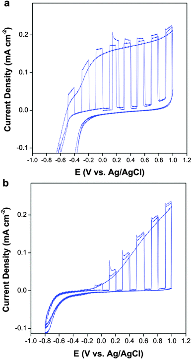 | ||
| Fig. 6 Photocurrent density of (a) B-TiO2 and (b) undoped TiO2 (both deposited at 550 °C) in 0.1 M KNO3 under simulated solar UV irradiation (10 mW cm−2). | ||
Conclusions
Boron doped TiO2 films were deposited using chemical vapour deposition of titanium(IV) chloride, ethyl acetate and triisopropyl borate, which to the authors' knowledge is the first example of thin film boron doped TiO2 made by CVD. The films were analysed using XRD and Raman spectroscopy and were crystalline TiO2 with no additional phases present. The samples made at lower temperature (500 and 550 °C) were anatase and rutile at higher temperatures (600 °C). Raman spectroscopy revealed a shift in the Eg anatase band for B-doped samples, attributed to the presence of the dopant and decrease in crystallite size as compared to undoped samples.The composition of the films was analysed using XPS and coupled with a contraction in the unit cell observed by calculation of lattice parameters of the films, it was thought the B dopant was incorporated into the TiO2 lattice in an O-substitutional position, changing the orientation and microstructure of the material. Remarkable rates of hydrogen production were observed in the doped films when compared to non-doped samples as well as having more favourable photocurrent profiles. The films were also shown to be active for water oxidation. In light of this boron doped TiO2 APCVD films of low cost could be manufactured on a reel-to-reel process for photodiodes, which could be used for water reduction and oxidation. The improvement in photocatalysis on boron doping could also be utilised in wider applications such as water purification, dye-sensitised solar cells and antimicrobial surfaces.
Acknowledgements
The authors would like to thank the EPSRC (EPSRC grant codes EP/J500136/1, EP/J500148/1) for funding as well as Tata Steel, Teer Coatings and TWI for allied funding. X-ray photoelectron spectra were obtained at the National EPSRC XPS User's Service (NEXUS) at Newcastle University, an EPSRC Mid-Range Facility.Notes and references
- J. L. Sawin and E. Martinot, REN21, 2011.
- A. Fujishima and K. Honda, Nature, 1972, 238, 37–38 CrossRef CAS.
- R. Dholam, N. Patel, A. Santini and A. Miotello, Int. J. Hydrogen Energy, 2010, 35, 9581–9590 CrossRef CAS PubMed.
- T. Sun, J. Fan, E. Liu, L. Liu, Y. Wang, H. Dai, Y. Yang, W. Hou, X. Hu and Z. Jiang, Powder Technol., 2012, 228, 210–218 CrossRef CAS PubMed.
- R. Asahi, T. Morikawa, T. Ohwaki, K. Aoki and Y. Taga, Science, 2001, 293, 269–271 CrossRef CAS PubMed.
- J. C. Yu, J. G. Yu, W. K. Ho, Z. T. Jiang and L. Z. Zhang, Chem. Mater., 2002, 14, 3808–3816 CrossRef CAS.
- T. Umebayashi, T. Yamaki, H. Itoh and K. Asai, Appl. Phys. Lett., 2002, 81, 454–456 CrossRef CAS.
- H. Q. Sun, S. B. Wang, H. M. Ang, M. O. Tade and Q. Li, Chem. Eng. J., 2010, 162, 437–447 CrossRef CAS PubMed.
- S. U. M. Khan, M. Al-Shahry and W. B. Ingler, Science, 2002, 297, 2243–2245 CrossRef CAS PubMed.
- W. Y. Choi, A. Termin and M. R. Hoffmann, J. Phys. Chem., 1994, 98, 13669–13679 CrossRef.
- S. In, A. Orlov, R. Berg, F. Garcia, S. Pedrosa-Jimenez, M. S. Tikhov, D. S. Wright and R. M. Lambert, J. Am. Chem. Soc., 2007, 129, 13790–13791 CrossRef CAS PubMed.
- V. Gombac, L. De Rogatis, A. Gasparotto, G. Vicario, T. Montini, D. Barreca, G. Balducci, P. Fornasiero, E. Tondello and M. Graziani, Chem. Phys., 2007, 339, 111–123 CrossRef CAS PubMed.
- D. Chen, D. Yang, Q. Wang and Z. Y. Jiang, Ind. Eng. Chem. Res., 2006, 45, 4110–4116 CrossRef CAS.
- K. L. Choy, Prog. Mater. Sci., 2003, 48, 57–170 CrossRef CAS.
- G. Hyett, J. A. Darr, A. Mills and I. P. Parkin, Chem.–Eur. J., 2010, 16, 10546–10552 CrossRef CAS PubMed.
- G. Hyett, J. A. Darr, A. Mills and I. P. Parkin, Chem. Vap. Deposition, 2010, 16, 301–304 CrossRef CAS.
- A. J. Nozik, Annu. Rev. Phys. Chem., 1978, 29, 189–222 CrossRef CAS.
- A. J. Cross, C. W. Dunnill and I. P. Parkin, Chem. Vap. Deposition, 2012, 18, 133–139 CrossRef CAS.
- X. J. Feng, J. Zhai and L. Jiang, Angew. Chem., Int. Ed., 2005, 44, 5115–5118 CrossRef CAS PubMed.
- G. Liu, J. C. Yu, G. Q. Lu and H. M. Cheng, Chem. Commun., 2011, 47, 6763–6783 RSC.
- U. Diebold, Surf. Sci. Rep., 2003, 48, 53–229 CrossRef CAS.
- A. Fujishima, X. T. Zhang and D. A. Tryk, Surf. Sci. Rep., 2008, 63, 515–582 CrossRef CAS PubMed.
- V. Shklover, M. K. Nazeeruddin, S. M. Zakeeruddin, C. Barbe, A. Kay, T. Haibach, W. Steurer, R. Hermann, H. U. Nissen and M. Gratzel, Chem. Mater., 1997, 9, 430–439 CrossRef.
- M. Lazzeri, A. Vittadini and A. Selloni, Phys. Rev. B: Condens. Matter Mater. Phys., 2001, 63, 155409 CrossRef.
- M. Lazzeri, A. Vittadini and A. Selloni, Phys. Rev. B: Condens. Matter Mater. Phys., 2002, 65, 1 Search PubMed.
- T. Ohno, K. Sarukawa and M. Matsumura, New J. Chem., 2002, 26, 1167–1170 RSC.
- W. F. Zhang, Y. L. He, M. S. Zhang, Z. Yin and Q. Chen, J. Phys. D: Appl. Phys., 2000, 33, 912–916 CrossRef CAS.
- T. Ohsaka, F. Izumi and Y. Fujiki, J. Raman Spectrosc., 1978, 7, 321–324 CrossRef.
- A. Kafizas and I. P. Parkin, J. Am. Chem. Soc., 2011, 133, 20458–20467 CrossRef CAS PubMed.
- D. Bersani, P. P. Lottici and X. Z. Ding, Appl. Phys. Lett., 1998, 72, 73–75 CrossRef CAS.
- J. C. Parker and R. W. Siegel, J. Mater. Res., 1990, 5, 1246–1252 CrossRef CAS.
- Z. Zhang, S. Brown, J. B. M. Goodall, X. Weng, K. Thompson, K. Gong, S. Kellici, R. J. H. Clark, J. R. G. Evans and J. A. Darr, J. Alloys Compd., 2009, 476, 451–456 CrossRef CAS PubMed.
- A. S. Pottier, S. Cassaignon, C. Chaneac, F. Villain, E. Tronc and J. P. Jolivet, J. Mater. Chem., 2003, 13, 877–882 RSC.
- J. A. Schreifels, P. C. Maybury and W. E. Swartz, J. Catal., 1980, 65, 195–206 CrossRef CAS.
- G. Mavel, J. Escard, P. Costa and J. Castaing, Surf. Sci., 1973, 35, 109–116 CrossRef CAS.
- W. Zhao, W. H. Ma, C. C. Chen, J. C. Zhao and Z. G. Shuai, J. Am. Chem. Soc., 2004, 126, 4782–4783 CrossRef CAS PubMed.
- X. Ding, X. Song, P. Li, Z. Ai and L. Zhang, J. Hazard. Mater., 2011, 190, 604–612 CrossRef CAS PubMed.
- Y. M. Wu, M. Y. Xing and J. L. Zhang, J. Hazard. Mater., 2011, 192, 368–373 CAS.
- M. Murata, K. Wakino and S. Ikeda, J. Electron Spectrosc. Relat. Phenom., 1975, 6, 459–464 CrossRef CAS.
- M. Kitano, M. Takeuchi, M. Matsuoka, J. A. Thomas and M. Anpo, Catal. Today, 2007, 120, 133–138 CrossRef CAS PubMed.
- X. Zhao, W. Jin, J. Cai, J. Ye, Z. Li, Y. Ma, J. Xie and L. Qi, Adv. Funct. Mater., 2011, 21, 3554–3563 CrossRef CAS.
- J. M. Li and D. S. Xu, Chem. Commun., 2010, 46, 2301–2303 RSC.
- N. Feng, A. Zheng, Q. Wang, P. Ren, X. Gao, S.-B. Liu, Z. Shen, T. Chen and F. Deng, J. Phys. Chem. C, 2011, 115, 2709–2719 CAS.
- S. Elouali, A. Mills, I. P. Parkin, E. Bailey, P. F. McMillan and J. A. Darr, J. Photochem. Photobiol., A, 2010, 216, 110–114 CrossRef CAS PubMed.
- M. W. Kanan and D. G. Nocera, Science, 2008, 321, 1072–1075 CrossRef CAS PubMed.
- A. Kudo and Y. Miseki, Chem. Soc. Rev., 2009, 38, 253–278 RSC.
- M. G. Walter, E. L. Warren, J. R. McKone, S. W. Boettcher, Q. Mi, E. A. Santori and N. S. Lewis, Chem. Rev., 2010, 110, 6443–6936 CrossRef PubMed.
- F. Meng, J. Li, S. K. Cushing, J. Bright, M. Zhi, J. D. Rowley, Z. Hong, A. Manivannan, A. D. Bristow and N. Wu, ACS Catal., 2013, 3, 746–751 CrossRef CAS.
- N. Lu, X. Quan, J. Y. Li, S. Chen, H. T. Yu and G. H. Chen, J. Phys. Chem. C, 2007, 111, 11836–11842 CAS.
- S. Saremi-Yarahmadi, K. G. U. Wijayantha, A. A. Tahir and B. Vaidhyanathan, J. Phys. Chem. C, 2009, 113, 4768–4778 CAS.
- T. K. Townsend, E. M. Sabio, N. D. Browning and F. E. Osterloh, Energy Environ. Sci., 2011, 4, 4270–4275 CAS.
- J. X. Zhu, Z. Y. Yin, D. Yang, T. Sun, H. Yu, H. E. Hoster, H. H. Hng, H. Zhang and Q. Y. Yan, Energy Environ. Sci., 2013, 6, 987–993 CAS.
Footnote |
| † Electronic supplementary information (ESI) available. See DOI: 10.1039/c3cp52665h |
| This journal is © the Owner Societies 2013 |