 Open Access Article
Creative Commons Attribution 3.0 Unported Licence
Individual dispersion of carbon nanotubes in epoxy via a novel dispersion–curing approach using ionic liquids†
Nishar
Hameed
*a,
Nisa V.
Salim
a,
Tracey L.
Hanley
b,
Mrunali
Sona
a,
Bronwyn L.
Fox
a and
Qipeng
Guo
*a
aInstitute for Frontier Materials, Deakin University, Locked Bag 2000, Geelong, Victoria 3220, Australia. E-mail: nishar.hameed@deakin.edu.au; qguo@deakin.edu.au
bInstitute Materials Engineering, Australian Nuclear Science and Technology Organisation, Lucas Heights, New South Wales 2234, Australia
First published on 15th May 2013
Abstract
The effective dispersion of carbon nanotubes (CNTs) in a thermoset was achieved using ionic liquid as the dispersion–curing agent. We preferentially dispersed multiwalled carbon nanotubes (MWCNTs) down to individual tube levels in epoxy resin. Here the dispersion is ruled by the depletion of physical bundles within the MWCNT networks, for which molecular ordering of ionic liquids is considered responsible. The quantitative analyses using ultra small angle X-ray scattering (USAXS) confirmed the dispersion of individual MWCNTs in the matrix. The distance between the dispersed nanotubes was calculated at different nanotube loadings using the power law fitting of the USAXS data. The fine dispersion and subsequent curing, both controlled by ionic liquid, lead to composites with substantially enhanced fracture mechanical and thermomechanical properties with no reduction in thermal properties. Merging processing techniques of nanocomposites with ionic liquid for efficient dispersion of nanotubes and preferential curing of thermosets facilitates the development of new, high performance materials.
Introduction
Development of high performance materials by the incorporation of carbon nanotubes (CNTs) into polymer matrices has been difficult because thermodynamic and kinetic barriers inhibit the effective dispersion of nanotubes. The incorporation and uniform dispersion of carbon nanotubes in epoxy thermosets could facilitate engineers to create materials that potentially compete with the most advanced materials in nature.1 The unique combination of outstanding mechanical, thermal, and electrical properties of CNTs makes them excellent nanofillers for the fabrication of advanced materials. Successful enhancement in mechanical and electrical properties via reinforcement is expected only when the nanofillers are well dispersed within the polymer matrix. Moreover, the orientation, as well as the CNT/matrix interfacial strength, also determines the effective physical properties of these materials.2–5 However, CNTs, having a high aspect ratio and a large π-electronic surface, typically assemble to give bundles which are heavily entangled with one another. The common dispersing methods such as solution mixing for the preparation of nanocomposites are a concern as CNTs repel most polar and nonpolar solvents.6 Surface functionalization has been used to improve the dispersion of CNTs,7,8 however it deteriorates the intrinsic properties of these fillers except for some very recent studies.9 Therefore, the dispersion of CNTs down to an individual tube level in polymers remains a great challenge and despite numerous advances, polymer–CNTs composites have yet to demonstrate the expected property improvements.Fukushima et al., achieved a superior dispersion of CNTs in room temperature ionic liquid (IL) by mixing single walled carbon nanotubes (SWCNTs) with 1-butyl-3-methylimidazolium tetrafluoroborate (BMIMBF4).10 These SWCNT–IL mixtures or ‘bucky gels’ are highly stable and the nanotubes are finely dispersed due to the orientation of CNTs in IL by possible ‘imidazolium cation–π’ interactions.11 Generally CNTs adhere tightly to each other due to strong π–π stacking interactions, making it very difficult to disperse by common solvents. When CNTs and IL mixed together the shear force detaches the nanotubes from the bundles and the tubes are then wrapped by IL.12 It is proposed that the π–π stacking interactions of nanotubes are shielded by the high dielectric constants of IL restricting them from rebundling. Moreover it is found that IL can disperse a higher concentration of CNTs than surfactants or DNA.13 This molecular ordering and interaction may initiate the dispersion of CNTs in ILs and high performance polymer based composites can be efficiently prepared by taking advantage of a strong affinity of the imidazolium ion toward the π-electronic nanotube surface. In another important study, ILs were used as thermally latent initiators for polymerization of epoxy resins.14,15 BMIMBF4 and recently, 1-ethyl-3-methylimidazolium dicyanamide [EmiN(CN)2] have been successfully used as the hardener for epoxy resins. The ionic liquid is incorporated into the polymer during curing and forms a cross-linked epoxy network with bulky counterions.15–18
In this work, we present an investigation of highly dispersed multiwalled carbon nanotubes (MWCNTs) in epoxy by combining the outstanding dispersing and hardening efficiency of ILs. The ionic liquid, BMIMBF4, was used to disperse MWCNTs in epoxy and then composites with superior mechanical properties were prepared. In other words BMIMBF4 acts as both a dispersing agent for MWCNTs and a curing initiator for epoxy resin. In the final material, BMIMBF4 becomes a part of the crosslinked matrix. Here, the cost advantage of MWCNTs over SWCNTs and dispersing potential of BMIMBF4 over other ILs can provide an alternative route for the preparation of new functional materials. Recent studies of epoxy nanocomposites try to achieve maximum properties at low filler concentrations to make them cost-effective and therefore, composites at low nanotube loadings were investigated. Moreover, the cost of IL is also equitable considering the relatively small fraction of ILs used here as an additive. The whole process has thus a potential to make cost-effective composites to be used in aerospace and automotive applications.
Results and discussion
Epoxy suspensions and composites containing 0.05 to 1 wt% of MWCNTs were prepared using the IL dispersion–curing method. The MWCNT dispersion capacity of ionic liquids in epoxy was verified using USAXS techniques. Epoxy–MWCNT suspensions containing 0.5% BMIMBF4 were used to analyze the dispersion properties. A dedicated analysis of USAXS data at various q regions enables us to quantitatively demonstrate the rigid rod behavior and crossover network behavior of viscous CNT solutions and their cured composites. The level of dispersion was measured first in viscous suspensions of epoxy + BMIMBF4 + MWCNTs prior to curing. We have physically observed that, below 0.5 wt% of MWCNT concentration, the suspensions flow freely under the influence of gravity and above this point, the suspensions show physical gel behavior as shown in Fig. 1.19 This gelation implies that further dispersion is achievable, however eventually network formation will limit the degree of dispersion that could be achieved. The gelation is apparently due to the formation of networks owing to the overlapping of individual MWCNTs or their bundles depending on the dispersion state (Fig. 1d). The average distance between the two neighboring contact points in the network is the mesh size (ξ).19 The concentration dependence of ξ can be determined from SAXS intensity profiles to quantify the network crossover effect. The ξ value is expected to decrease with increasing CNT concentrations.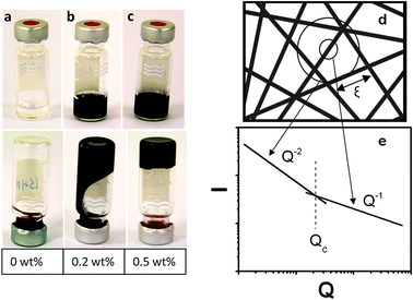 | ||
| Fig. 1 Photographs of MWCNT suspensions in epoxy + BMIMBF4 mixtures. The concentration of BMIMBF4 is 0.5 wt% to epoxy. (a) Epoxy + BMIMBF4 mixture without MWCNTs, flows slowly when turn upside down. (b) Suspension containing 0.2 wt% MWCNTs. (c) Suspension containing 0.5 wt% MWCNTs forms a physical gel. (d) Possible structure of MWCNT dispersion in suspensions, ξ is the crossover point that gives the average distance between the intersections of the crosslinked network. (e) The typical scattering profile model illustrating the crossover point in a suspension.19 | ||
CNTs can be considered as rigid rods and scattering intensity from stable solutions of individual CNTs or rod-like CNT bundles is expected to exhibit a Q−1 intensity variation.20 On the other hand weakly dispersed CNT solutions show Q−2 variation in scattering intensity. The USAXS scattering profiles of MWCNT suspensions stabilized by BMIMBF4 and epoxy are shown in Fig. 2. The upturn in scattering for samples containing MWCNTs at Q < 0.01 A−1 is due to the presence of dispersed nanotubes.21 The rigid rod (Q−1) and network structure (Q−2) contributions are highlighted in each figure and Qc represents the crossover point. In the USAXS profiles the low Q scattering is due to the MWCNTs dispersed in the solution and it clearly demonstrates the power law behavior. The intermediate scattering that arises from the epoxy + BMIMBF4 mixture and the higher flat Q region is the incoherent scattering. Considering distinct scattering patterns, the total scattering intensity can be divided into three parts namely; power law MWCNT scattering, solvent scattering from the epoxy + BMIMBF4 mixture and the incoherent background scattering.
 | (1) |
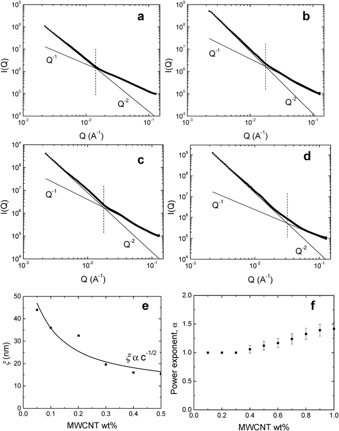 | ||
| Fig. 2 USAXS scattering profiles of epoxy + BMIMBF4 + MWCNT suspensions at low nanotube concentrations. The concentration of BMIMBF4 was kept constant at 0.5 wt% of epoxy. (a) 0.05 wt%, (b) 0.1 wt%, (c) 0.2 wt%, and (d) 0.3 wt% of MWCNTs. The solid lines in figures (a–d) represent the best fit values to eqn (1) in the text and the vertical dotted lines represent the crossover points. (e) The variation in mesh size (ξ) with concentration of MWCNTs. The solid line represents the theoretical change in mesh size according to the explanation in the text. (f) The power law exponents of suspensions with respect to the MWCNT concentration. | ||
The mesh size ξ was determined by the crossover point of Q−1 to Q−2 power law behavior (ξ = 2π/Qc) and the observed values for MWCNT suspensions in the epoxy + BMIMBF4 mixture are given in Fig. 2e. The value of ξ decreases indicating that the nanotubes are getting close to each other with an increase in concentration of MWCNTs. Theoretically for cylindrical rods in semidilute concentration regimes the mesh size is proportional to the concentration (c) of rods, i.e., ξ ∝ 1/√c.23 This relation is also shown by solid lines in Fig. 2e. From the figure, it is clear that the composites show less deviation from the theoretical values. The crossover behavior was observed for suspensions up to 0.3 wt% of MWCNTs however above this composition, a power law dependence on exponents having values higher than 1 (α > 1) was observed. The value of α can be used to quantitatively determine the level of dispersion; a better dispersion can be assumed if α is close to 1. Fig. 2f shows the α for different suspensions at varying MWCNT concentrations. The α increases with an increase in the nanotube concentrations which is attributed to the formation of MWCNT bundles and a wide distribution of size and structures.22 The results of epoxy suspensions containing BMIMBF4 were also compared with those without BMIMBF4 to see the level of dispersion where scattering intensity behavior with α > 2 was observed in all cases (not given here). This demonstrates the excellent capability of BMIMBF4 to disperse carbon nanotubes.
Epoxy composites containing 0.1–1 wt% of MWCNTs were prepared using the mixture 4,4′-methylenedianiline (MDA) + BMIMBF4 as a curing agent. The amount of BMIMBF4 was previously optimized to be 0.5% of epoxy for the best dispersion and mechanical performance and then a stoichiometric amount of MDA was employed (ESI†). The efficacy of the BMIMBF4 in exfoliating and dispersing MWCNTs in epoxy composites is again demonstrated using SAXS data shown in Fig. 3a–c. The SAXS measurements were acquired on 25 mm × 25 mm × 2 mm composite strips using a 1 mm beam at 2 mm intervals. The scattering profiles of 1 wt% MWCNT composites are shown in Fig. 3b and c. The SAXS profiles of composites prepared using BMIMBF4 as dispersing medium are identical at all positions of the strip (Fig. 3b) whereas those without ionic liquid differ both in intensity and scattering vector, Q-values (Fig. 3c).
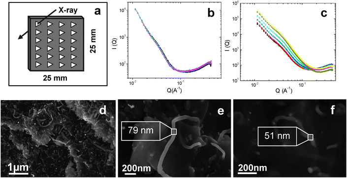 | ||
| Fig. 3 (a) A representation of SAXS mapping experiments on 25 mm × 25 mm × 2 mm composite strips where measurements were taken at every 2 mm intervals to investigate the homogeneity of dispersion. (b) The SAXS profiles of epoxy + BMIMBF4 + MWCNTs (1 wt%) composites taken according to a. (c) The SAXS profiles of epoxy + MWCNT composites with no BMIMBF4. (d) High resolution SEM image of 1 wt% MWCNT composites with BMIMBF4. (e) The magnified SEM image of an individual nanotube in 1 wt% MWCNT composites with BMIMBF4 (diameter ∼80 nm), and (f) the magnified view individual nanotube in 1 wt% MWCNT composites without BMIMBF4 where the diameter is only ∼50 nm. | ||
The finely dispersed MWCNTs in the epoxy matrix can be observed in the high resolution scanning electron microscope (SEM) image shown in Fig. 3d. The SEM images show dispersed and randomly oriented individual MWCNTs in 1 wt% composites. It can be suggested that due to the interaction between MWCNTs and ionic liquid, large nanotube aggregates would split into small segregates or individual tubes and become well dispersed in the epoxy matrix. To investigate the level of adhesion between the matrix and nanotubes, a comparison in the size of the individual nanotubes has been performed using the SEM images of composites prepared with and without BMIMBF4. It is surprising that the average diameter of nanotubes is ∼80 nm in composites where BMIMBF4 was added as a dispersing–curing agent. These individual nanotubes in the epoxy matrix are shown in Fig. 3e. The larger diameters observed suggest that the nanotubes were wrapped in or covered by a BMIMBF4 + epoxy layer, indicating good adhesion between the matrix and MWCNTs. On the other hand, the average diameter of nanotubes was found to be around 50 nm in the case of composites prepared without BMIMBF4 (Fig. 3f). This is consistent with the diameter range of as-received MWCNTs as provided by the manufacturer (40–60 nm), indicating that there is no epoxy wetting or adhesion between MWCNTs and the matrix.
The composite samples were further examined using Raman spectroscopy (Fig. 4) to verify that the dispersion of MWCNTs using BMIMBF4 resulted in physical adsorption at the interface rather than disturbing the CNT structure to introduce defects. The two most distinguished features of CNTs in Raman spectra are the D and G bands observed at wave numbers of ∼1350 cm−1 and ∼1580 cm−1, respectively. The G band represents sp2 hybridized carbon networks and the G band denotes the disorder-induced character. The integrated ratio of intensity of these bands (ID/IG) can be used as an indication of defect density of nanotubes. It can be seen that there is no significant changes in the position or intensity of D and G bands or the intensity ratio in samples with and without ionic liquid. This indicates that the dispersion of MWCNTs using BMIMBF4 was effective in epoxy without damaging nanotube walls. Moreover, the interaction between the matrix and MWCNTs can be verified by a peak width change in the spectra.24 It is observed that the peak at 1270 cm−1 is shifted to a higher wavenumber region (1274 cm−1) in composites containing IL and its width is narrower compared to the one without IL. This is due to the interaction of MWCNTs with surrounding polymer chains at the interface.25
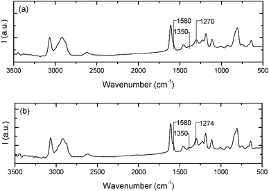 | ||
| Fig. 4 Raman spectra of (a) epoxy + BMIMBF4 + MWCNTs and (b) epoxy + MWCNT composites (1 wt%) in the frequency range 3500–500 cm−1. | ||
The thermomechanical properties of neat epoxy and nanocomposites are presented in Fig. 5a–d. The glass transition temperature (Tg) and storage modulus of the different samples, at several temperatures, are summarized in Table 1. The storage modulus of nanocomposites is remarkably higher than that of the neat epoxy at temperatures below Tg and then this value becomes similar for all the samples above Tg. The incorporation of only 0.1 wt% of MWCNTs led to 33% improvement in the storage modulus of glassy epoxy at 30 °C which is considered to be significant. The storage modulus value steadily increases with the amount of MWCNTs up to 1 wt% and becomes marginal above this concentration. All the composites showed higher Tg values compared to neat epoxy. The synergic behavior in Tg was again confirmed from differential scanning calorimetry (DSC) experiment results. Interestingly Tg of all composites show higher values, the maximum Tg was shown by 0.5 wt% composites (∼182 °C) which is about 9 degree higher than the neat epoxy thermoset (Fig. S1 in the ESI†). Generally there appears to be a reduction in Tg of epoxy upon the addition of any fillers. However, it was proven in our previous experiments that epoxy cured using the BMIMBF4 + MDA mixture shows an improvement in Tg by at least 8–10 °C than that cured with MDA alone (Table S1, ESI†). Here, this synergic effect was retained even after the addition of MWCNTs. Moreover it was confirmed from thermal decomposition experiments that the thermal stability of the composites was increased marginally with the addition of MWCNTs (Fig. S2, ESI†).
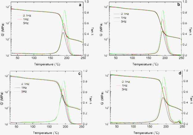 | ||
Fig. 5 Variation in storage modulus (G′) and tan![[thin space (1/6-em)]](https://www.rsc.org/images/entities/char_2009.gif) δ with temperature at different frequencies (0.1, 1 and 5 Hz) of epoxy + BMIMBF4 + MWCNT composites containing (a) 0 wt%, (b) 0.1 wt% (c) 0.5 wt% and (d) 1 wt% MWCNTs. δ with temperature at different frequencies (0.1, 1 and 5 Hz) of epoxy + BMIMBF4 + MWCNT composites containing (a) 0 wt%, (b) 0.1 wt% (c) 0.5 wt% and (d) 1 wt% MWCNTs. | ||
| Wt% of MWCNTs in epoxy | Tensile strength (MPa) | Young's modulus (GPa) | Tensile strain (%) | T g (DMTA) (°C) | Storage modulus (GPa) (DMTA) | ||
|---|---|---|---|---|---|---|---|
| At 30 °C | 150 °C | At rubbery plateau (Tg + 50 °C) | |||||
| 0 | 55.68 ± 3 | 2.32 ± 0.05 | 6.17 | 190 | 7.53 | 4.76 | 0.09 |
| 0.1 | 59.25 ± 2 | 2.48 ± 0.09 | 7.79 | 191 | 9.65 | 5.56 | 0.10 |
| 0.5 | 68.25 ± 2 | 2.62 ± 0.05 | 8.39 | 192 | 10.60 | 6.08 | 0.10 |
| 1 | 60.09 ± 2 | 2.36 ± 0.03 | 6.16 | 192 | 11.16 | 7.14 | 0.11 |
The fracture toughness was measured to investigate the effect of efficient nanotube dispersion on the fracture mechanical properties. The plain-strain fracture toughness (K1C) and critical energy release rate (G1C) values of the neat epoxy and nanocomposites are summarized in Fig. 6a and b. It is clear that the resistance to fracture was significantly improved by the addition of MWCNTs. The largest improvement in K1C by 95% compared to neat epoxy was observed for 0.7 wt% MWCNT composites. The increase in fracture toughness can be attributed to the good level of MWCNT dispersion in IL up to 0.7 wt% concentration. This improvement is significant considering the fact that the total loading of CNT is only 0.7 wt% and the epoxy has a high cross-link density.
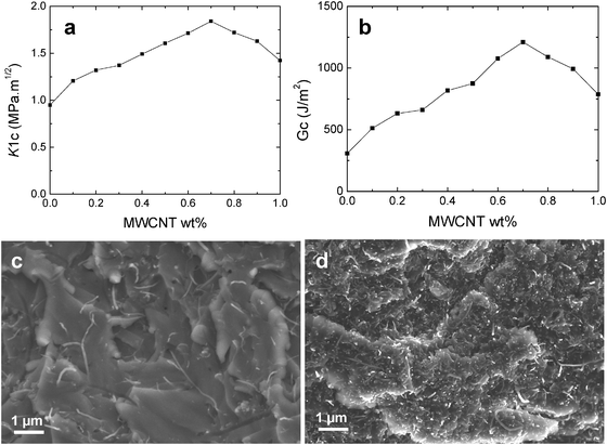 | ||
| Fig. 6 (a) K1C and (b) G1C fracture properties of the epoxy composites with different MWCNT contents. (c) SEM fracture images of composites without BMIMBF4 dispersion. Individual nanotubes are randomly distributed on the fractured surface showing no interfacial compatibility between the matrix and the nanotubes. (d) Composites with BMIMBF4 as the dispersion–curing agent. MWCNTs are dispersed well within the matrix showing excellent adhesion. | ||
Generally the increase in toughness is at the expense of tensile strength and Young's modulus in the case of epoxy blends and composites. However, here the tensile properties of the composites are also increased at low MWCNT addition as shown in Table 1. It can be suggested that BMIMBF4 addition in epoxy composites has led to a higher interfacial bonding. The SEM images of the fractured surface at high magnification of composites with and without ionic liquid have been compared. The images are shown in Fig. 6c and d respectively. In the case of composites without ionic liquid, nanotubes are pulled out from the matrix and randomly seen on the surface that underlines a poor adhesion. Although with ionic liquid BMIMBF4 as a dispersion–curing agent, nanotubes break at fracture instead of slipping and appear to be projecting out of the fracture surface which indicates a good interfacial adhesion. It is difficult to ascertain the mechanism of fracture toughness improvement at this point; however, a possible assumption is that the formation of a unique epoxy network structure with a definite asymmetric distribution of cross-links around the carbon nanotubes enhances the ductility of the matrix.
The thermomechanical and fracture properties of the composites prepared using IL have been compared with existing epoxy–CNT composites prepared via other routes and are shown in Table S2 (ESI†). The most common methods involve the use of solvents, surfactants or block copolymers as dispersing agents for CNTs or functionalization of CNTs. Most of the studies reported an unchanged Tg or a reduction in Tg occurs by the incorporation of nanotubes into the matrix.26–34 From Table S2 (ESI†), it is clear that IL is the simple and effective dispersion–curing agent that can significantly improve the toughness of the matrix without deteriorating other physical properties. This is obviously due to the high level of nanotube dispersion achieved in IL as proven by the scattering studies.
Conclusions
The dispersion–curing method using ionic liquid outlined here allows the fabrication of highly dispersed nanotubes/epoxy suspensions and nanocomposites with superior properties. The role of the ionic liquid is to function as a dispersing agent prior to curing and later as a curing agent. It can be assumed that the addition of the ionic liquid also has an effect on the wetting behavior, and on the interfacial adhesion, which in return has an impact on the ionic liquid's ability to exfoliate the nanotubes. The composites at low nanotube loading showed exceptionally high fracture mechanical strength and modulus without reduction in tensile properties. The interfacial chemistry of carbon nanotubes with the ionic liquid and epoxy should be an important subject for future research.Experimental section
Multiwalled carbon nanotubes (MWCNTs) were obtained from Shenzhen Nano-Tech Co Ltd. The nanotubes were with a diameter of 40–60 nm and a length of 1–2 μm. The epoxy precursor diglycidyl ether of bisphenol A (DGEBA) with epoxide equivalent weight of 172–176 and the curing agent 4,4′-methylenedianiline (MDA) were purchased from Aldrich Chemical Co. The ionic liquid 1-butyl-3-methylimidazolium tetrafluoroborate (BMIMBF4) was from Merck. The chemicals were used as received to simplify the process.For USAXS measurements the MWCNTs were suspended in a solution of the epoxy + BMIMBF4 mixture, sonicated for 1 hour and then mechanically stirred for 2 hours. For the fabrication of epoxy composites a method based on the mixing of MWCNTs and resin was used. Pre-weighed amounts of MWCNTs were first suspended in the epoxy + BMIMBF4 mixture and then sonicated for 1 hour. The suspension was then mechanically stirred for 2 hours using an Ika Werke RW16 high speed mixer at 1200 rpm and then MDA was added. After complete dissolution of MDA, the whole mixture was poured into pre-heated moulds and cured at 150 °C for 10 hours and then post-cured at 180 °C for 2 hours.
USAXS experiments were performed at the Australian Synchrotron on the ultra-small and small angle X-ray scattering beamline utilizing an undulator source that allows measurement at a very high flux to moderate scattering angles and a good flux at the minimum q limit. The experiments were conducted at room temperature and the wavelength of X-ray was 0.062 nm. The intensity profiles were interpreted from the plot of scattering intensity (I) versus scattering vector, q = (4π/λ)![[thin space (1/6-em)]](https://www.rsc.org/images/entities/char_2009.gif) sin(θ/2) (θ is the scattering angle). Raman spectra were recorded with a Perkin Elmer Raman station 400 spectrometer using Helium laser excitation. The samples were scanned from 400 cm−1 to 3624 cm−1 at a resolution of 4 cm−1. Dynamic mechanical tests were performed on a dynamic mechanical thermal analyzer (DMTA) (TA Q800, USA) in a cantilever mode. The frequency was 1 Hz at a heating rate of 3 °C min−1. The specimen dimensions were 60 × 12 × 3 mm3. The storage modulus, loss modulus and tan
sin(θ/2) (θ is the scattering angle). Raman spectra were recorded with a Perkin Elmer Raman station 400 spectrometer using Helium laser excitation. The samples were scanned from 400 cm−1 to 3624 cm−1 at a resolution of 4 cm−1. Dynamic mechanical tests were performed on a dynamic mechanical thermal analyzer (DMTA) (TA Q800, USA) in a cantilever mode. The frequency was 1 Hz at a heating rate of 3 °C min−1. The specimen dimensions were 60 × 12 × 3 mm3. The storage modulus, loss modulus and tan![[thin space (1/6-em)]](https://www.rsc.org/images/entities/char_2009.gif) δ were measured from 30 to 250 °C. The Tg was taken as the maximum of the tan
δ were measured from 30 to 250 °C. The Tg was taken as the maximum of the tan![[thin space (1/6-em)]](https://www.rsc.org/images/entities/char_2009.gif) δ curve in the glass transition region. For fracture toughness measurements, the single-edge-notch three point-bending (SENB) test was used according to ASTM standard D5045. The tests were performed on an Instron 30 kN instrument at a test speed of 2 mm min−1. An initial crack was generated carefully by tapping the thumbnail shape crack front using a fresh razor blade prior to testing. K1C and G1C of the samples were determined by testing five specimens. The tensile properties of the composites were measured on an Instron 30 kN SD tensile testing machine. The tests were conducted with dumb-bell shaped specimens according to ASTM standard D638. At least five specimens were tested to obtain the average values of tensile properties for all the specimens.
δ curve in the glass transition region. For fracture toughness measurements, the single-edge-notch three point-bending (SENB) test was used according to ASTM standard D5045. The tests were performed on an Instron 30 kN instrument at a test speed of 2 mm min−1. An initial crack was generated carefully by tapping the thumbnail shape crack front using a fresh razor blade prior to testing. K1C and G1C of the samples were determined by testing five specimens. The tensile properties of the composites were measured on an Instron 30 kN SD tensile testing machine. The tests were conducted with dumb-bell shaped specimens according to ASTM standard D638. At least five specimens were tested to obtain the average values of tensile properties for all the specimens.
Acknowledgements
SAXS/WAXS research was undertaken at the Australian Synchrotron, Victoria, Australia, and the authors thank Dr Nigel Kirby and Dr Adrian Hawley for their assistance. The authors thank Dr Joel Davis at Australian Nuclear Science and Technology Organisation (ANSTO) for SEM imaging. The authors thank Dr Muthu Pannirselvam at the Rheology and Materials Processing Centre (RMPC), RMIT University for Raman experiments. We also thank the Australian Institute of Nuclear Science and Engineering (AINSE) Ltd for an award (ALNGRA 11157) for the SAXS measurements.References
- S. M. Liff, N. Kumar and G. H. McKinley, Nat. Mater., 2007, 6, 76 CrossRef CAS.
- P. M. Ajayan, L. S. Schadler, C. Giannaris and A. Rubio, Adv. Mater., 2000, 12, 750 CrossRef CAS.
- P.-C. Ma, S.-Y. Mo, B.-Z. Tang and J.-K. Kim, Carbon, 2010, 48, 1824 CrossRef CAS.
- L. Schadler, Appl. Phys. Lett., 1998, 73, 3842 CrossRef CAS.
- J. Suhr, N. Koratkar, P. Keblinski and P. Ajayan, Nat. Mater., 2005, 4, 134 CrossRef CAS.
- L. Jeongwoo, K. Myunghun, K. H. Chang and E. S. Sang, Meas. Sci. Technol., 2007, 18, 3707 CrossRef.
- J. Zhu, J. Kim, H. Peng, J. L. Margrave, V. N. Khabashesku and E. V. Barrera, Nano Lett., 2003, 3, 1107 CrossRef CAS.
- J. Zhu, H. Peng, F. Rodriguez-Macias, J. L. Margrave, V. N. Khabashesku, A. M. Imam, K. Lozano and E. V. Barrera, Adv. Funct. Mater., 2004, 14, 643 CrossRef CAS.
- O. Osazuwa, K. Petrie, M. Kontopoulou, P. Xiang, Z. Ye and A. Docoslis, Compos. Sci. Technol., 2012, 73, 27 CrossRef CAS.
- T. Fukushima, A. Kosaka, Y. Ishimura, T. Yamamoto, T. Takigawa, N. Ishii and T. Aida, Science, 2003, 300, 2072 CrossRef CAS.
- J. C. Ma and D. A. Dougherty, Chem. Rev., 1997, 97, 1303 CrossRef CAS.
- J. Wang, H. Chu and Y. Li, ACS Nano, 2008, 2, 2540 CrossRef CAS.
- M. Zheng, A. Jagota, E. D. Semke, B. A. Diner, R. S. McLean, S. R. Lustig, R. E. Richardson and N. G. Tassi, Nat. Mater., 2003, 2, 338 CrossRef CAS.
- K. Krzysztof and S. Tadeusz, Ionic liquids as convenient latent hardeners of epoxy resins: Rapid communications, Industrial Chemistry Research Institute, Warszawa, POLOGNE, 2003, p. 48 Search PubMed.
- M. A. M. Rahmathullah, A. Jeyarajasingam, B. Merritt, M. VanLandingham, S. H. McKnight and G. R. Palmese, Macromolecules, 2009, 42, 3219 CrossRef CAS.
- H. Zhang, Z. Wang, Z. Zhang, J. Wu, J. Zhang and J. He, Adv. Mater., 2007, 19, 698 CrossRef CAS.
- Z. Wang, X. Yang, Q. Wang, H. T. Hahn, S. Lee, K. H. Lee and Z. Guo, Int. J. Smart Nano Mater., 2011, 2, 176 CrossRef CAS.
- Z. Wang, H. A. Colorad, Z. H. Guo, H. Kim, C. L. Park, H. T. Hahn, S. G. Lee, K. H. Lee and Y. Q. Shang, J. Mater. Res., 2012, 15, 510 CrossRef CAS.
- L. A. Hough, M. F. Islam, B. Hammouda, A. G. Yodh and P. A. Heiney, Nano Lett., 2006, 6, 313 CrossRef CAS.
- W. Zhou, Chem. Phys. Lett., 2004, 384, 185 CrossRef CAS.
- K. Yurekli, C. A. Mitchell and R. Krishnamoorti, J. Am. Chem. Soc., 2004, 126, 9902 CrossRef CAS.
- H. Wang, W. Zhou, D. L. Ho, K. I. Winey, J. E. Fischer, C. J. Glinka and E. K. Hobbie, Nano Lett., 2004, 4, 1789 CrossRef CAS.
- C. F. Schmidt, M. Baermann, G. Isenberg and E. Sackmann, Macromolecules, 1989, 22, 3638 CrossRef CAS.
- Q. Zhao and H. D. Wagner, Philos. Trans. R. Soc., A, 2004, 362, 2407 CrossRef CAS.
- L. Valentini, J. Biagiotti, J. M. Kenny and S. Santucci, Compos. Sci. Techol., 2003, 63, 1149 CrossRef CAS.
- M. R. Loos, J. Yang, D. L. Feke and I. Manas-Zloczower, Compos. Sci. Techol., 2012, 72, 482 CrossRef CAS.
- L. Guadagno, B. De Vivo, A. Di Bartolomeo, P. Lamberti, A. Sorrentino, V. Tucci, L. Vertuccio and V. Vittoria, Carbon, 2011, 49, 1919 CrossRef CAS.
- L. C. Tang, H. Zhang, J. Han, X. Wu and Z. Zhang, Compos. Sci. Techol., 2011, 72, 7 CrossRef CAS.
- G. Gkikas, N.-M. Barkoula and A. S. Paipetis, Composites, Part B, 2012, 43, 2697 CrossRef CAS.
- J. Shen, W. Huang, L. Wu, Y. Hu and M. Ye, Composites, Part A, 2007, 38, 1331 CrossRef.
- F. H. Gojny, M. H. G. Wichmann, B. Fiedler and K. Schulte, Compos. Sci. Techol., 2005, 65, 2300 CrossRef CAS.
- R. Hollertz, S. Chatterjee, H. Gutmann, T. Geiger, F. A. Nuesch and B. T. T. Chu, Nanotechnology, 2011, 22, 125702 CrossRef CAS.
- L. Sun, G. L. Warren, J. Y. O'Reilly, W. N. Everett, S. M. Lee, D. Davis, D. Lagoudas and H.-J. Sue, Carbon, 2008, 46, 320 CrossRef CAS.
- S. Cuia, R. Caneta, A. Derrea, M. Couzib and P. Delhaes, Carbon, 2003, 41, 797 CrossRef.
Footnote |
| † Electronic supplementary information (ESI) available: Ionic liquid optimization, Tg-composition plots, DSC thermograms and thermogravimetric curves. See DOI: 10.1039/c3cp00064h |
| This journal is © the Owner Societies 2013 |
