DOI:
10.1039/C2CE26253C
(Paper)
CrystEngComm, 2013,
15, 182-191
Self-assembled MgxZn1−xO quantum dots (0 ≤ x ≤ 1) on different substrates using spray pyrolysis methodology
Received
5th August 2012
, Accepted 12th October 2012
First published on 16th October 2012
Abstract
By using the spray pyrolysis methodology in its classical configuration we have grown self-assembled MgxZn1−xO quantum dots (size ∼4–6 nm) in the overall range of compositions 0 ≤ x ≤ 1 on c-sapphire, Si (100) and quartz substrates. Composition of the quantum dots was determined by means of transmission electron microscopy-energy dispersive X-ray analysis (TEM-EDAX) and X-ray photoelectron spectroscopy. Selected area electron diffraction reveals the growth of single phase hexagonal MgxZn1−xO quantum dots with composition 0 ≤ x ≤ 0.32 by using a nominal concentration of Mg in the range 0 to 45%. Onset of Mg concentration about 50% (nominal) forces the hexagonal lattice to undergo a phase transition from hexagonal to a cubic structure which resulted in the growth of hexagonal and cubic phases of MgxZn1−xO in the intermediate range of Mg concentrations 50 to 85% (0.39 ≤ x ≤ 0.77), whereas higher nominal concentration of Mg ≥ 90% (0.81 ≤ x ≤ 1) leads to the growth of single phase cubic MgxZn1−xO quantum dots. High resolution transmission electron microscopy and fast Fourier transform confirm the results and show clearly distinguishable hexagonal and cubic crystal structures of the respective quantum dots. A difference of 0.24 eV was detected between the core levels (Zn 2p and Mg 1s) measured in quantum dots with hexagonal and cubic structures by X-ray photoemission. The shift of these core levels can be explained in the frame of the different coordination of cations in the hexagonal and cubic configurations. Finally, the optical absorption measurements performed on single phase hexagonal MgxZn1−xO QDs exhibited a clear shift in optical energy gap on increasing the Mg concentration from 0 to 40%, which is explained as an effect of substitution of Zn2+ by Mg2+ in the ZnO lattice.
Introduction
The development of nanotechnology, both at academic and industrial levels, has allowed an advance in the miniaturization of optoelectronic and electronic devices and it has allowed a significant step to the increase in data storage capacity.1–3 In order to improve the existing technology, intense research is being carried out on nanostructured materials, namely on zero dimensional materials. Zero dimensional materials, known as quantum dots (QDs), in which the electronic motion is confined in all the three spacial dimensions, are of technological importance due to interesting enhanced excitonic radiative recombination and size-dependent tuning of spectral emissions towards short-wavelength region.4 Quantum confinement effects modify the profile of density of states in quantum dots so that the transfer integral at the band-edge enhances much higher than in bulk or quantum wells, facilitating efficient stimulated emission and resulting in high efficient operation of devices at low threshold energy density.5 Due to the technological importance, quantum dots of various materials InAs, GaAs, InP, CdS, ZnO are being widely studied. More in particular, ZnO has gained utmost attention among researchers due to its possible applications in short-wavelength lasers and LEDs.5–9 One of the features of ZnO is its band gap potential tunability to a wide range from 3.37 to 6.7 eV via magnesium incorporation into ZnO lattice (MgxZn1−xO).10 Films of MgxZn1−xO exist in two different phases with hexagonal and cubic structures depending on the Mg concentration.10,11 Maintaining hexagonal structure the optical band gap of MgxZn1−xO could be enhanced up to 4.3 eV,11 whereas the cubic phase takes the advantage of extending the band gap to a value very close to 6.7 eV.10 The possibility of tuning the band gap in MgxZn1−xO to higher energies is encouraging for current technology of UV lasers and photo-detectors. Until now, major research works have been focused on MgxZn1−xO thin films,12–14 and there are only few reports published on the growth of MgxZn1−xO QDs15 or free nanoparticles/nanostructures.16–20 In particular, Zeng et al.15 obtained MgxZn1−xO QDs of size ∼9 nm on Si (100) substrates using low pressure Metal Organic Chemical Vapour Deposition (MOCVD) technique. However the study was limited only up to 2.3 at% of Mg incorporation into the ZnO lattice. Table 1 summarizes the range of compositions, sizes and the different phases of MgxZn1−xO nanoparticles obtained by various researchers using different growth techniques.21,22
Table 1 Range of compositions, sizes and some details of the MgxZn1−xO nanoparticles obtained by using different growth techniques
| Serial No. |
Authors |
Range of ‘x’ |
Growth technique |
Substrate |
Cubic (C)/Hexagonal (H) |
| 1. |
Manoranjan et al.16 |
0 ≤ x ≤ 0.17 |
Solution route |
— |
H |
| (size: 10–12 nm) |
x ≥ 0.2 |
Mixed phase |
| 2. |
Manuel et al.21 |
0 < x < 0.19 |
Polymer based method |
— |
H |
| (size: 95–172 nm) |
x ≥ 0.19 |
Mixed phase |
| 3. |
Guangqiang et al.20 |
0 < x < 0.21 |
Polymer based method |
— |
H |
| (size: 20–50 nm) |
0.21 ≤ x ≤ 0.73 |
Mixed phase |
|
x ≥ 0.82 |
C |
| 4. |
Xianyong et al.22 |
x = 0.3 |
Sono-chemical method |
— |
H |
| (size: 180 nm) |
| 5. |
John et al.18 |
x ≤ 0.3 |
Thermal decomposition |
— |
H |
| (size: 40 nm) |
x > 0.3 |
Mixed phase |
| 6. |
Zeng et al.15 |
x = 0.01 and 0.23 |
LP-MOCVD |
Si |
H |
| (size: 9 nm) |
Recently our group showed the availability of the spray pyrolysis (SP) methodology for the growth of zero dimensional ZnO QDs on various substrates (c-Al2O3, quartz and glass).23 By controlling the precursor concentration, growth temperature and growth time, a wide range of QD densities (∼2 × 10¹⁰ to 3.5 × 10¹¹ QDs cm−2) and sizes (5 to 14 nm) were obtained. In the present work, by using the SP technique we focus on the growth of MgxZn1−xO quantum dots on c-sapphire and Si (100) substrates, which have different crystal structures and are present in current technology. We have carried out a systematic study of the incorporation of Mg into the ZnO lattice, and vice versa, Zn on the MgO lattice, in the overall range of compositions (0 ≤ x ≤ 1). The SP methodology has been adopted and adapted for the growth of MgxZn1−xO QDs because it is one of the most inexpensive, simple and easily scalable techniques used for the deposition of semiconductor, metal oxide thin films and nanostructures.23–25 Compared with other current epitaxial growth technology, SP technique would benefit the industrial scale production. To date no reports have been published, to the best of our knowledge, on the growth of MgxZn1−xO quantum dots on substrates in the overall range of Mg concentration (0 ≤ x ≤ 1), and hence this work opens up a new way for obtaining the QDs and application of these QDs in devices operating in the UV range.
Experimental
Magnesium zinc oxide nanoparticles were deposited onto pre-heated substrates with various crystal structures (hexagonal c-sapphire, cubic Si (100) and amorphous quartz) from solid free zinc diacetate dihydrate (Zn(CH3COO)2·2H2O) and magnesium acetate (Mg(CH3COO)2·4H2O) (Fisher Scientific, Laboratory reagent grade) solution dissolved in methanol (Scharlau, reagent grade). Composition of Mg in the MgxZn1−xO nanoparticles is controlled by adjusting the Mg concentration (magnesium acetate) in the starting precursor solution. From the previous study on ZnO QDs we have selected a set of experimental conditions in order to obtain a narrow range of sizes and densities.23 Precursor concentration of 0.0125 M and growth temperature of 315 °C were used for depositing the QDs. The atomised precursor, generated by means of a spray nozzle, was sprayed onto the substrates using nitrogen as carrier gas (99.999%). The rate of spray was kept constant at 14.7 ml min−1 while the substrate to nozzle distance was kept constant for the experiments at 28 cm, so that a uniform spray of about 21 cm in diameter span arrived at the substrate. The morphology of the samples was studied by using a Hitachi S-4800 field emission electron microscope (acceleration voltage: 30 kV). A conductive layer of gold–palladium was deposited over the QDs using dc-sputtering prior to the scanning electron microscopy (SEM) analysis. The thickness of gold-palladium coating was about 1 nm, so that an increase in size of about 2 nm of MgxZn1−xO QDs covered by the coating is expected. High resolution transmission electron micrographs (HR-TEM), energy dispersive X-ray analysis (EDAX) and selected area electron diffractions (SAED) were recorded with a Tecnai G2 F20 field emission gun transmission electron microscope under an acceleration voltage of 200 kV. For TEM-EDAX and SAED measurements, MgxZn1−xO QDs were deposited on TEM support carbon film on copper grid substrates (C-grid) placed over a heated c-sapphire substrate. Particle size and morphology of the MgxZn1−xO QDs were studied by analysing over 200–300 particles from HR-TEM. Fast Fourier transform (FFT) performed on HRTEM recorded from QDs were used to determine the crystal structure of the MgxZn1−xO QDs. TEM-EDAX spectra were recorded from MgxZn1−xO QDs by using an EDAX-AMETEK detector and composition of the MgxZn1−xO QDs was determined. X-ray photoelectron spectroscopy (XPS) measurements of ZnO and MgxZn1−xO QDs were performed in an ultra-high vacuum system ESCALAB210 (base pressure 1.0 × 10⁻¹⁰ mbar) from Thermo VG Scientific. The samples were fixed onto the sample holder and a contact was made from the sample surface to the holder by means of silver paint to prevent the sample from becoming extensively charged while emitting electrons. The measurements were taken over an area of 1 mm2. Photoelectrons were excited by using the Al Kα line (1.4866 keV). As a reference in the binding energy, we used the C 1s peak (fixed to 285 eV). XPS compositional analyses were performed on MgxZn1−xO QDs grown on sapphire substrate (Mg concentration: 0 to 100%) by considering empirical atomic sensitivity factors of the Mg 1s and Zn 2p core levels.26 Thus the atomic sensitivity factor of the Mg 1s core level was found to be 3.5 when photoelectrons are excited by the Al Kα line.26 Nevertheless, available atomic-sensitivity-factor value for the Zn 2p3/2 core level (4.8) was related to photoelectrons excited from this level by using a Mg Kα line. Taking in mind that we have excited with the Al Kα line, the use of that atomic-sensitivity-factor value for the Zn 2p3/2 core level limits, a little bit, the quantitative accuracy, in particular in the middle and Zn-rich composition regions. Finally, the room temperature absorption coefficient has been estimated for the MgxZn1−xO QDs deposited on quartz using a Jasco V650 spectrophotometer working in transmission mode. A reference quartz template without MgxZn1−xO QDs has been measured and the signal subtracted from the MgxZn1−xO spectra. The spectrophotometer covers the 200 to 800 nm spectral region by using a deuterium and a halogen lamp, and thus nominally allows the analysis of material with band gap energies up to ∼6–6.5 eV.
Results and discussion
As said before, on the basis of the previous study on ZnO QDs we have fixed precursor concentration and growth temperature to obtain MgxZn1−xO QDs of sizes in the range of ∼4–6 nm, and densities in the order of ∼1011 QD cm−2 to cover about ∼13% of the substrate.23 Representative scanning electron micrographs are depicted in Fig. 1–3. As a first finding, the study shows that under the experimental conditions here chosen, the MgxZn1−xO QDs can be grown irrespective of the crystal structure of the substrate (c-Al2O3, Si (100) and amorphous quartz), without any significant difference in the morphological characteristics of the QDs. The most probable reason to obtain similar surface morphology irrespective of the crystal structure of the substrate may be due to the growth of QDs over a wetting layer, which is formed underneath the QDs 23. Uniform and well isolated MgxZn1−xO QDs ranging between ∼4–6 nm in size, densities in the range of ∼1011 QDs cm−2 and a Mg nominal concentration between 0 and 40% over c-Al2O3 substrate can be seen in Fig. 1a and b (and on silicon in Fig. 2a and b). For Mg nominal concentrations ≥50%, and maintaining same growth conditions, a decrease in the QD density and size was observed (due to decrease of growth rate). Hence to obtain QDs of similar size and densities, growth time was varied between 1 and 4 minutes for growth in the range of Mg concentrations 0.09 < x < 0.81, whereas a growth time of 6 minutes was used for the growth of MgO QDs.
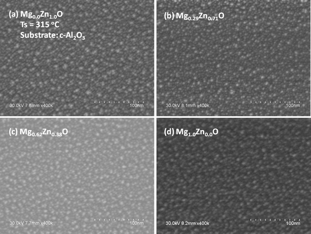 |
| | Fig. 1 SEM micrographs of MgxZn1−xO QDs grown on c-Al2O3 with Mg concentration (nominal) (a) 0%, (b) 40%, (c) 80% and (d) 100% at a growth temperature of 315 °C. | |
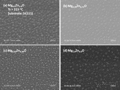 |
| | Fig. 2 SEM micrographs of MgxZn1−xO QDs grown on Si (100) with Mg concentration (nominal) (a) 0%, (b) 40%, (c) 80% and (d) 100% at a growth temperature of 315 °C. | |
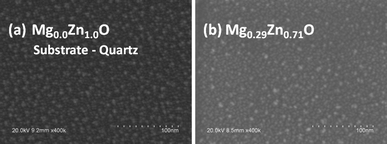 |
| | Fig. 3 SEM micrographs of MgxZn1−xO QDs grown on quartz with Mg concentration (nominal) (a) 0% and (b) 40%. | |
Structural characterisation of MgxZn1−xO QDs
Taking into account the low influence of the substrate (Si (100), c-Al2O3, quartz and glass)23 on the morphological properties of ZnO QDs under the experimental conditions used in this study, TEM and SAED analysis of the MgxZn1−xO QDs with various Mg concentrations were performed on samples deposited over carbon-grid substrates, maintaining similar growth conditions. Fig. 4 and 5 depict the TEM images of MgxZn1−xO QDs grown over C-grid with Mg concentrations ranging from 0 to 50% and 70 to 100% (nominal), respectively. Uniform and isolated QDs of sizes in the range of 2–4 nm can be observed from the TEM micrographs (Fig. 4 and 5). It is worth to note that the QDs size measured using SEM image gives an overestimated value due to the Au–Pd coatings and SEM microscope's resolution.27
 |
| | Fig. 4 TEM images of MgxZn1−xO QDs grown on C-grid with Mg nominal concentration (a) 0%, (b) 10%, (c) 30% and (d) 50% at a growth temperature of 315 °C. | |
 |
| | Fig. 5 TEM images of MgxZn1−xO QDs grown on C-grid with Mg nominal concentration (a) 70%, (b) 80%, (c) 90% and (d) 100% at a growth temperature of 315 °C. | |
SAED spectra were recorded on those samples deposited over C-grid substrates (Mg nominal concentration: 0 to 100%) and the electron diffraction rings were indexed (Fig. 6). The radius of the electron diffraction ring r(hkl) and the inter-planar lattice spacing d(hkl) are related by r(hkl) × d(hkl) = Lλ, where Lλ = 1 is the camera constant of the transmission electron microscope. From the electron diffraction pattern, r is measured and the lattice spacing d is determined. The experimental d-values determined from the SAED pattern of Mg0.0Zn1.0O (ZnO) QDs are 2.819, 2.6319, 2.5100, 1.9500, 1.6630, 1.5065 and 1.4050 Å corresponding to the planes (100), (002), (101), (102), (110), (103) and (200) respectively, which are indexed as the wurtzite phase of ZnO (JCPDS: 36-1451) with space group P63mc (Fig. 6a). It is worth noticing that no diffraction rings corresponding to metallic Zn, Mg or any other impurities are observed, showing the purity of the MgxZn1−xO QDs grown using SP. Similarly, the electron diffraction rings recorded from the Mg1.0Zn0.0O (MgO) QD samples were indexed to the cubic MgO (space group Fm3m) (Fig. 6f). The d-values determined from the MgO QD sample were 2.5608, 2.2078, 1.5873, 1.2944, 0.9732 and 0.8933 Å corresponding to the planes (111), (200), (220), (311), (331) and (422) respectively (JCPDS: 045-0946).
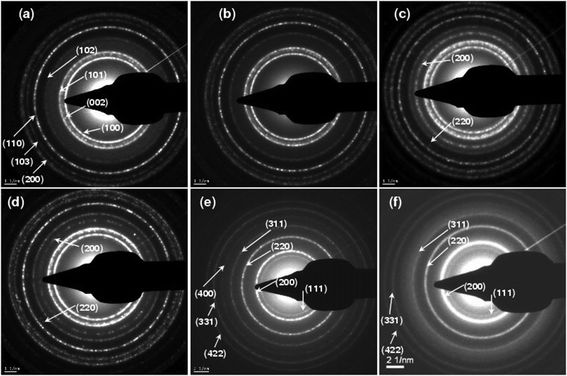 |
| | Fig. 6 SAED patterns recoded from MgxZn1−xO QDs samples deposited on C-grid with Mg concentration (a) 0%, (b) 30%, (c) 50%, (d) 70%, (e) 90% and (f) 100%. | |
Careful analysis of electron diffraction patterns for the MgxZn1−xO QD samples reveals that only diffraction rings corresponding to the hexagonal alloy MgxZn1−xO are present up to a Mg nominal concentration of 45%. No diffraction rings from the MgO phase were observed in SAED patterns, indicating that the material (MgxZn1−xO) is present only in its hexagonal phase (single phase) and magnesium has been incorporated into the ZnO lattice. Onset of Mg content (in the precursor solution) about 50% resulted in appearance of additional diffraction rings along (200) and (220) planes corresponding to the cubic MgxZn1−xO alloy, showing co-existence of hexagonal and cubic phases of the QDs in the range 50 to 85%. Further increase in Mg concentration to values greater than or equal to 90% in the precursor solution results in the growth of a single phase cubic alloy with characteristic electron diffraction rings of the cubic MgxZn1−xO. All the diffraction rings corresponding to hexagonal phase of MgxZn1−xO were absent for those nominal concentrations higher than 90% (showing a complete phase transition from hexagonal P63mc space group to cubic Fm3m space group).
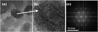
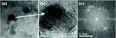
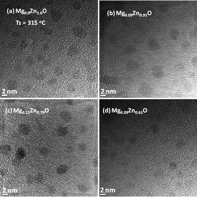
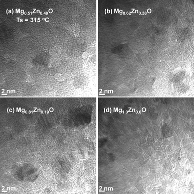
High resolution TEM characterization has been used to have a close look at the crystalline properties of the MgxZn1−xO QDs. Fig. 7a depicts the HRTEM micrograph of the Mg0.21Zn0.79O nanoparticles (nominal concentration of Mg: 30%), whereas Fig. 7b shows the magnified HRTEM image of one nanoparticle (see Fig. 7a). The inter-planar distance measured from the HRTEM image is in good agreement with the values determined using SAED analysis. Fast Fourier transform (FFT) performed in the selected nanoparticle shows the associated hexagonal crystal structure (Fig. 7c). Similar FFT study conducted of Mg0.81Zn0.09O shows the cubic crystal structure corresponding to this composition (Fig. 8c). However, one can clearly distinguish the cubic and hexagonal phases of MgxZn1−xO alloy from HRTEM (Fig. 7b and 8b) and FFT (Fig. 7c and 8c) images. Thus by using HRTEM and FFT analysis it is possible to identify and distinguish the MgxZn1−xO QDs of various crystal structures. The HRTEM profile of cubic MgxZn1−xO thin film reported by Liang et al. closely matches with the profile obtained in the present study from cubic MgxZn1−xO QDs.28 In brief, high resolution TEM and SAED analysis proved that the hexagonal symmetry of the MgxZn1−xO are preserved/maintained up to a Mg nominal concentration of 45% (x ≤ 0.32) and Mg substitution does not lead to any change in crystal structure.
Effect of Mg incorporation
Compositional analysis of MgxZn1−xO QDs was carried out using XPS as well as TEM-EDAX measurements. TEM-EDAX spectra were recorded from MgxZn1−xO QD samples deposited on C-grid, whereas XPS compositional analyses were performed on MgxZn1−xO QDs grown on sapphire substrate (Mg concentration: 0 to 100%). Fig. 9 shows the evolution of measured atomic concentration of Mg from MgxZn1−xO QD samples (determined using EDAX and XPS) as a function of magnesium nominal concentration in the starting precursor solution. As the concentration of Mg in the precursor solution was increased, the actual Mg content in MgxZn1−xO QDs was gradually enhanced; however the actual concentration of Mg in the samples was less than the nominal concentration in the precursor solution. The low efficiency of Mg incorporation into ZnO lattice is an experimental fact due to the solubility limit of Mg in the hexagonal ZnO lattice. The hexagonal crystal structure of ZnO does not have atomic/Wyckoff positions to accommodate the excess Mg atoms supplied from the precursor solution, and hence the Mg atoms compete with the lattice to modify the crystal structure (from hexagonal to cubic) for accommodating higher number of Mg atoms. In a hexagonal ZnO unit cell there are two tetrahedrally-coordinated (Td) Zn atoms, whereas in cubic MgO unit cell there are four octahedrally-coordinated (Oh) Mg atoms.
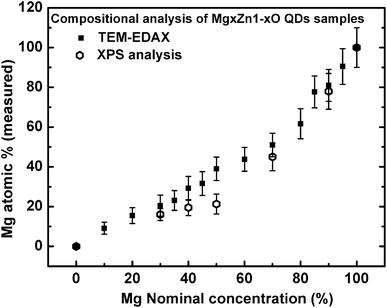 |
| | Fig. 9 Evolution of magnesium content in MgxZn1−xO QD samples (determined using TEM-EDAX and XPS) as a function of Mg nominal concentration in the starting precursor solution. | |
However, MgxZn1−xO QDs grown with Mg concentrations lower than 45% (nominal) were able to accommodate the Mg in a single hexagonal phase. Nevertheless on increasing the Mg concentration to a value of 50% (nominal), cubic phase of MgxZn1−xO appeared in the SAED spectrum, Fig. 6c. In fact, onset of the Mg concentration about 50% forces the hexagonal lattice to undergo a phase transition to cubic phase in order to accommodate more number of Mg atoms. Further increase of Mg concentration higher than 50% (nominal) resulted in a continuous increase in the overall Mg concentration (actual).
The lower Mg incorporation in ZnO QD (Mg concentration in the range 10 to 50% (nominal) can be understood in the frame of the lower impurity solubility limit in nanocrystals/QDs in accordance with the “self-purification” model proposed by Gustavo et al.29 One of the major factors that limits the doping efficiency or alloying of nanoparticles is the surface binding energy of the dopant atoms on the individual nanocrystals surface. It has been demonstrated in a classical paper by Steven et al. that the doping efficiency is determined by the binding energy of the dopant atoms on the individual nanocrystals surface.30 The surface binding energy for wurtzite nanocrystals is three times less than that of zinc-blende or rock-salt structures on (001) faces.16,30 Therefore in the present study, it seems that the lower incorporation of Mg in ZnO lattice with respect to the nominal concentration of Mg in the starting precursor solution is also related to the crystal structure of ZnO, in addition to other limits in the miscibility as could be inferred from the phase diagram corresponding to the alloy as a bulk crystal.31 Hence during the growth of MgxZn1−xO (at lower Mg concentrations) all the Mg atoms supplied from the precursor are not bound/incorporated to the lattice, and eventually get desorbed from the lattice resulting in the formation of MgxZn1−xO QDs with lower Mg concentration (with respect to the concentration in precursor solution). Unlikely, if we consider the incorporation of Zn in MgO lattice (cubic), the efficiency is higher, which resulted in the growth of Mg0.91Zn0.09O, Mg0.81Zn0.19O and Mg0.62Zn0.38O with a Zn concentration of 5, 10 and 20% in the starting precursor solution.
From the inter-planar distance (d-values) determined by means of SAED analysis, lattice parameters of hexagonal (“a”and “c”) and cubic (“a”) phases of MgxZn1−xO QDs were determined using the following relation, respectively:32
Fig. 10a shows the evolution of the “a” and “c” lattice parameters of the hexagonal alloy MgxZn1−xO with Mg nominal concentration ranging from 0 to 100%. To determine “a” and “c” lattice parameters of the hexagonal QDs, electron diffraction rings corresponding to the (100) and (103) planes were used, whereas “a” lattice constant of cubic MgxZn1−xO QDs was determined using the (200) electron diffraction ring. Standard value of “a” and “c” lattice parameters of ZnO with hexagonal wurtzite structure are 3.2498 Å and 5.2066 Å respectively (JCPDS: 36-1451). In the basis of the present study, we can observe an increase in the a-lattice parameter and a decrease in c-lattice parameter of hexagonal alloy MgxZn1−xO QDs upon increasing the Mg concentration. The variation in the value of lattice parameters recorded from MgxZn1−xO QD samples has been reported as clear evidence of the substitution of Zn2+ sites by Mg2+ in ZnO lattice to form a MgxZn1−xO alloy.11,21,33 The a-lattice parameter gradually increased with increase in Mg concentration up to 30% (measured value x = 0.21), thereafter the change in the lattice constant with increase in nominal Mg concentration was very small up to Mg concentration of 50%. The small change in lattice constant observed near the Mg concentration range where the secondary cubic phase appeared (50% nominal) indicated that the incorporation of Mg in ZnO lattice is very low in this concentration range. However further increase in the Mg concentration to 70 and 80% (nominal), exhibited wide change in a-lattice constant. A similar behavior was observed in the case of c-lattice constant, where the c-lattice constant decreased on increasing Mg concentration. This increase in the a-lattice constant (and decrease in c-lattice constant) is attributed to the hexagonal-to-cubic phase transition undergone on increasing the Mg concentration. However the presence of mixed phases (hexagonal and cubic) limits us to determine the actual stoichiometry of the sample at which the phase transition occurs. The variation in lattice parameter that appears on varying the Mg concentration is due to the substitution of tetrahedrally co-ordinated (Td) Zn2+ sites by Mg2+. However due to smaller ionic radius of Mg2+, substitution of Zn2+ by Mg2+ force the c-lattice parameter to shrink due to the strain exerted by the Mg substitution on the ZnO lattice upon increasing the Mg concentration.11,16,34 Similarly a corresponding elongation of a-lattice parameter is observed in ref. 21 and 32. Likewise, introducing Zn to the cubic MgO lattice resulted in substitution of octahedrally co-ordinated (Oh) Mg2+ by Zn2+ and a reduction in a-lattice parameter is observed (Fig. 10b), which is attributed to the distortion of the parent cubic MgO structure upon Zn incorporation. In addition a saturation of a-lattice parameter is observed in the mixed phase region, due to the solubility limit of Zn in cubic MgO lattice. When Mg is introduced into ZnO lattice, at an amount higher than 32 at%, ZnO starts to dissolve in the MgO matrix. Under such circumstances, mixed phases of cubic and hexagonal MgxZn1−xO co-exist. This is in accordance with the reported values of phase separation observed in MgxZn1−xO nanocrystals (>30 at%) by John et al.18 However Manoranjan et al.,16 Manuel et al.21 and Guangqiang et al.20 observed phase separation at about x ≥ 0.2 in MgxZn1−xO nanocrystals. The differences in the value of Mg concentration in which the phase separation appears point to the influence of growth method, presence or absence of a substrate and QDs size. It is worth noticing that the c-lattice constant of the MgxZn1−xO QDs (x = 0) observed in the present study (Fig. 10a) is higher than the standard value of hexagonal ZnO due to the surface stress on the ZnO nanocrystals. The stress causes a high lattice strain and leads to lattice expansion in order to relieve the strain.35 This fact indicates that in the MgxZn1−xO QDs grown using spray pyrolysis method, the stress relaxes elastically. Sameer et al. demonstrated in CeO2 nanoparticles (size 3 to 150 nm) that the surface stress induced by reduction in particle size modifies the lattice constant in a wide range.35 Similarly the cubic MgO QD also exhibited a higher value of a-lattice constant with respect to the standard bulk cubic MgO (c = 4.2112 Å) (Fig. 10), as a new evidence of the fact that the reduction in crystallite size influences the lattice constant of MgxZn1−xO QDs.
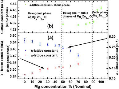 |
| | Fig. 10 Evolution of the lattice parameters of (a) hexagonal and (b) cubic magnesium zinc oxide alloy QDs as a function of magnesium concentration. The lines are drawn just to guide the reader's eyes. | |
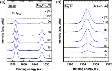 |
| | Fig. 11 XPS spectra of (a) Zn 2p and (b) Mg 1s core levels measured in MgxZn1−xO QDs grown on c-Al2O3. The nominal Mg concentration of the QDs is indicated on each curve. Solid blue lines are Gaussian fitting of the experimental results. Vertical dashed lines in each plot indicate the energy position of the Zn 2p3/2 and Mg 1s core levels in ZnO and MgO QDs, respectively, as obtained by the fitting of the XPS spectra. | |
![Shift of the Zn 2p (open circles) and Mg 1s (filled circles) core levels measured in MgxZn1−xO QDs, with respect to these recorded in ZnO and MgO QDs, respectively. These shifts have been obtained by Gaussian fitting of the experimental spectra and the error bars are the standard deviation of the fitting parameters. To guide discussion, we have indicated the structure of the MgxZn1−xO QDs [hexagonal (H), cubic (C), or mixed phases (C + H)].](/image/article/2013/CE/c2ce26253c/c2ce26253c-f12.gif) |
| | Fig. 12 Shift of the Zn 2p (open circles) and Mg 1s (filled circles) core levels measured in MgxZn1−xO QDs, with respect to these recorded in ZnO and MgO QDs, respectively. These shifts have been obtained by Gaussian fitting of the experimental spectra and the error bars are the standard deviation of the fitting parameters. To guide discussion, we have indicated the structure of the MgxZn1−xO QDs [hexagonal (H), cubic (C), or mixed phases (C + H)]. | |
Optical characterisation
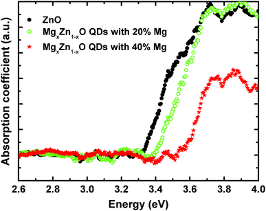
Optical absorption spectra in the wavelength range of 250–800 nm were recorded at room temperature from MgxZn1−xO QDs deposited on transparent quartz substrates. Samples with Mg concentrations ranging from 0 to 40% Mg (nominal values) were measured in transmission mode (Fig. 13), and the onsets to the optical absorption coefficient extracted from a linear extrapolation of the initial absorption slope. In this study we have focused on this range of magnesium content in which only a single hexagonal phase of MgxZn1−xO is present, avoiding disturbing effects due to the existence of mixed phases with undetermined singular composition.
As we can clearly observe in Fig. 13, the onset of the absorption coefficient, which approximately corresponds to the optical energy gap, shifted as a function of the Mg content from 0 to 40%, which is clear evidence of substitution of Zn2+ by Mg2+ in the ZnO lattice that yields an increase in the band gap energy. In order to confirm that the observed optical absorption actually results from the QDs and not from the wetting layer forming underneath, a sample was prepared only containing a wetting layer equivalent to that with the 40% Mg QDs (chosen to be representative sample of the series), but with no QDs on the surface. As seen in Fig. 14 the wetting layer by itself does not produce a measurable optical absorption. Thus, we can univocally assign the observed optical absorption coefficients to the wurtzite MgxZn1−xO QDs formed on the surface. Ning et al.36 performed optical transmission studies on MgxZn1−xO nanoparticles (30 nm size) in the range x = 0 to 0.2. These nanoparticles have been grown via sol–gel technique and dip coated on quartz substrates. Similarly as in our results a relatively small blue shift in optical absorption edge was observed on increasing Mg content. Our preliminary optical characterization confirms the ability of the alloy to modify significantly the ZnO optical properties by adding controlled amounts of magnesium without changing the crystalline structure.
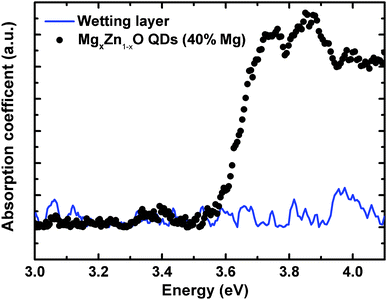 |
| | Fig. 14 Absorption spectra of MgxZn1−xO QDs and only wetting layer (without QDs) of same Mg content deposited on quartz substrate. | |
Conclusions
In summary, we have studied the growth of MgxZn1−xO QDs (0 ≤ x ≤ 1) on c-sapphire, Si (100) and quartz substrates by using the spray pyrolysis methodology. Composition of the Mg in MgxZn1−xO QDs is controlled by adjusting the Mg concentration in the starting precursor solution. The study proves that by controlling the Mg concentration from 0 to 45% (0 ≤ x ≤ 0.32, measured using TEM-EDAX) and 90 to 100% (0.81 ≤ x ≤ 1) the growth of single phase hexagonal MgxZn1−xO QDs or cubic MgxZn1−xO QDs can be successfully attained. The crystal structure suffer a phase transition from hexagonal to cubic structure on the onset of Mg concentration about 50%, which results in the growth of hexagonal and cubic phases of MgxZn1−xO in the intermediate range of Mg concentrations 50 to 85% (0.39 ≤ x ≤ 0.77). The study shows that the MgxZn1−xO QDs can be grown irrespective of the crystal structure of c-Al2O3 and Si (100) substrates, without any significant difference neither in the structural nor morphological characteristics of QDs. On the other hand, we have analysed the evolution of “a” and “c”-lattice parameters of the hexagonal MgxZn1−xO QDs with the increase in Mg concentration and similarly of the “a” parameter in the cubic MgxZn1−xO QDs. The study reveals that the surface binding energy and the crystal structure of the nanocrystals influence the incorporation of foreign atoms into the host lattice of nanocrystals. XPS measurements show that the segregation of cations is under the detection limit of the experimental setup and confirmed the substitution of tetrahedrally-coordinated (Td) Zn2+ by Mg2+ in the ZnO lattice. In addition to this, XPS results revealed that the core-level binding energies are determined by the structural properties and coordination of the QDs, irrespective of the cation. The optical measurements performed on MgxZn1−xO QDs exhibited the ability to tune the optical energy gap of the QDs to shorter wavelength of UV region, which is attributed to the substitution of Zn2+ by Mg2+ in the ZnO lattice. The ability, here shown, to obtain MgxZn1−xO QDs in an extended-range of concentrations on different substrates paves the way for additional studies that can shed light on the potential of the alloy in a zero dimensional configuration for devices operating in the UV region.
Acknowledgements
The authors are grateful to the Central Support Service in Experimental Research (SCSIE), University of Valencia, Spain for providing TEM and SEM facility. We are grateful to Antonio Jose Ibáñez González and Enrique Navarro Raga, SCSIE, University of Valencia for the co-operation during SEM measurements. The authors acknowledge funding received from Ministry of Science and Technology, Spain and EU (FEDER) through the projects MAT2007-66129, TEC 2011-28076, PIB2010JP-00279 and Generalitat Valenciana through the projects Prometeo/2011-035 and ISIC/2012/008 (Institute of Nanotechnologies for Clean Energies of the Generalitat Valenciana).
References
- K. Satoshi, S. Charles, H. Katsuyuki, G. Stephan, Y. Yoshihisa and A. Yasuhiko, Nat. Mater., 2006, 5, 887 CrossRef.
- T. Thomay, T. Hanke, M. Tomas, F. Sotier, K. Beha, V. Knittel, M. Kahl, K. M. Whitaker, D. R. Gamelin, A. Leitenstorfer and R. Bratschitsch, Opt. Express, 2008, 16, 9791 CrossRef CAS.
- L. Jang-Sik, C. Jinhan, L. Chiyoung, K. Inpyo, P. Jeongju, K. Yong-Mu, S. Hyunjung, L. Jaegab and C. Frank, Nat. Nanotechnol., 2007, 2, 790 CrossRef.
- L. Kuo-Feng, C. Hsin-Ming, H. Hsu-Cheng, L. Li-Jiaun and H. Wen-Feng, Chem. Phys. Lett., 2005, 409, 208 CrossRef.
- A. Ohtomo, M. Kawasakia, Y. Sakuraib, I. Ohkuboc, R. Shirokia, Y. Yoshidab, T. Yasudad, Y. Segawad and H. Koinumal, Mater. Sci. Eng., B, 1998, 56, 263 CrossRef.
- A. Tsukazaki, A. Ohtomo, T. Onuma, M. Ohtani, T. Makino, M. Sumiya, K. Ohtani, S. F. Chichibu, S. Fuke, Y. Segawa, H. Ohno, H. Koinuma and M. Kawasaki, Nat. Mater., 2005, 4, 42 CrossRef CAS.
- F. Shizuo, T. Hiroshi and F. Shigeo, J. Cryst. Growth, 2005, 278, 264 CrossRef.
- D. M. Bagnall, Y. F. Chen, Z. Zhu and T. Yao, Appl. Phys. Lett., 1997, 70, 2230 CrossRef CAS.
- Z. K. Tang, G. K. L. Wong, P. Yu, M. Kawasaki, A. Ohtomo, Y. Koinuma and Y. Segawa, Appl. Phys. Lett., 1998, 72, 3270 CrossRef CAS.
- J. Narayan, A. K. Sharma, A. Kvit, C. Jin, J. F. Muth and O. W. Holland, Solid State Commun., 2002, 121, 9 CrossRef.
- W. I. Park, Y. Gyu-Chul and H. M. Jang, Appl. Phys. Lett., 2001, 79, 2022 CrossRef CAS.
- A. K. Sharma, J. Narayan, J. F. Muth, C. W. Teng, C. Jin, A. Kvit, R. M. Kolbas and O. W. Holland, Appl. Phys. Lett., 1999, 75, 3327 CrossRef CAS.
- X. Mingshan, G. Qinlin, W. Kehui and G. Jiandong, J. Chem. Phys., 2008, 129, 234707 CrossRef.
- S. Choopun, R. D. Vispute, W. Yang, R. P. Sharma and T. Venkatesan, Appl. Phys. Lett., 2002, 80, 1529 CrossRef CAS.
- Y. J. Zeng, Z. Z. Ye, Y. F. Lu, J. G. Lu, L. Sun, W. Z. Xu, L. P. Zhu, B. H. Zhao and Y. Che, Appl. Phys. Lett., 2007, 90, 012111 CrossRef.
- G. Manoranjan and A. K. Raychaudhuri, J. Appl. Phys., 2006, 100, 034315 CrossRef.
- B. Leah, L. M. John, C. Xiang, H. Jesse and H. Heather, Appl. Phys. Lett., 2006, 88, 023103 CrossRef.
- L. M. John, H. Jesse, H. Heather, C. Erin, M. James, B. Leah and N. M. Grant, J. Appl. Phys., 2008, 104, 123519 CrossRef.
- H. Jesse, L. M. John, H. Heather, C. Erin, B. Leah, T. D. Pounds and M. G. Norton, Appl. Phys. Lett., 2007, 91, 111906 CrossRef.
- L. Guangqiang, L. Ingo and W. Gerhard, J. Am. Chem. Soc., 2006, 128, 15445 CrossRef.
- G. Manuel, R. Guillermo, A. Nuria and B. Salvador, J. Appl. Polym. Sci., 2011, 119, 2048 CrossRef.
- L. Xianyong, L. Zhaoyue, Z. Ying and J. Lei, Mater. Res. Bull., 2011, 46, 1638 CrossRef.
- R. Sreekumar, A. Said, R. Candid, F. S. R. Juan, M. T. M. Carmen and M. S. Vicente, Cryst. Growth Des., 2011, 11, 3790 Search PubMed.
- T. T. John, M. Mathew, K. C. Sudha, K. P. Vijayakumar, T. Abe and Y. Kashiwaba, Sol. Energy Mater. Sol. Cells, 2005, 89, 27 CrossRef CAS.
- T. Dedova, O. Volobujeva, J. Klauson, A. Mere and M. Krunks, Nanoscale Res. Lett., 2007, 2, 391 CrossRef CAS.
-
D. Briggs and M. P. Seah, in Practical Surface Analysis: Auger and X-ray Photoelectron Spectroscopy, ed. D. Briggs and M. P. Seah, John Wiley and Sons, Chichester, UK, 2nd edn, 1990, vol. 1, p. 156 Search PubMed.
- M. M. Haridas and J. R. Ballare, Colloids Surf., A, 1998, 133, 165 CrossRef CAS.
- J. Liang, H. Z. Wu, Y. F. Lao, N. B. Chen, P. Yu and T. N. Xu, Appl. Surf. Sci., 2005, 252, 1147 CrossRef CAS.
- M. D. Gustavo and R. C. James, Phys. Rev. Lett., 2006, 96, 226802 CrossRef.
- C. E. Steven, Z. Lijun, I. H. Michael, L. E. Alexander, A. K. Thomas and J. Norris, Nature, 2005, 436, 91 CrossRef.
- S. Detlev, B. Rainer, K. Detlef, S. Tobias and T. Elvira, J. Cryst. Growth, 2011, 33, 118 Search PubMed.
-
B. D. Cullity and S. R. Stock, Elements of X-rays Diffraction, Prentice Hall, New Jersey, USA, 3rd edn, 2001, p. 619 Search PubMed.
- A. Ohtomo, M. Kawasaki, T. Koida, K. Masubuchi, H. Koinuma, Y. Sakurai, Y. Yoshida, T. Yasuda and Y. Segawa, Appl. Phys. Lett., 1998, 72, 2466 CrossRef CAS.
- C. Y. Liu, H. Y. Xu, L. Wang, X. H. Li and Y. C. Liu, J. Appl. Phys., 2009, 106, 073518 CrossRef.
- D. Sameer, P. Swanand, V. N. T. K. Satyanarayana and S. Sudipta, Appl. Phys. Lett., 2005, 87, 133113 CrossRef.
- G.-H. Ning, X.-P. Zhao and J. Li, Opt. Mater., 2004, 27, 1 CrossRef CAS.
|
| This journal is © The Royal Society of Chemistry 2013 |
Click here to see how this site uses Cookies. View our privacy policy here.