 Open Access Article
 This Open Access Article is licensed under a Creative Commons Attribution-Non Commercial 3.0 Unported Licence
Toward optimal spatial and spectral quality in widefield infrared spectromicroscopy of IR labelled single cells
Eric C.
Mattson†
a,
Miriam
Unger†‡
a,
Sylvain
Clède
bcd,
François
Lambert
bcd,
Clotilde
Policar
bcd,
Asher
Imtiaz
e,
Roshan
D'Souza
e and
Carol J.
Hirschmugl
*a
aPhysics Dept., University of Wisconsin-Milwaukee, Milwaukee, WI, USA. E-mail: cjhirsch@uwm.edu
bEcole Normale Supérieure, Département de chimie, 24, rue Lhomond, 75005 Paris, France
cUniversité Pierre et Marie Curie Paris 6, 4, Place Jussieu, 75005 Paris, France
dLBM, CNRS, UMR7203, France
eMechanical Engineering Dept., University of Wisconsin-Milwaukee, Milwaukee, WI, USA
First published on 3rd July 2013
Abstract
Advancements in widefield infrared spectromicroscopy have recently been demonstrated following the commissioning of IRENI (InfraRed ENvironmental Imaging), a Fourier Transform infrared (FTIR) chemical imaging beamline at the Synchrotron Radiation Center. The present study demonstrates the effects of magnification, spatial oversampling, spectral pre-processing and deconvolution, focusing on the intracellular detection and distribution of an exogenous metal tris-carbonyl derivative 1 in a single MDA-MB-231 breast cancer cell. We demonstrate here that spatial oversampling for synchrotron-based infrared imaging is critical to obtain accurate diffraction-limited images at all wavelengths simultaneously. Resolution criteria and results from raw and deconvoluted images for two Schwarzschild objectives (36×, NA 0.5 and 74×, NA 0.65) are compared to each other and to prior reports for raster-scanned, confocal microscopes. The resolution of the imaging data can be improved by deconvolving the instrumental broadening that is determined with the measured PSFs, which is implemented with GPU programming architecture for fast hyperspectral processing. High definition, rapidly acquired, FTIR chemical images of respective spectral signatures of the cell and 1 shows that 1 is localized next to the phosphate- and Amide-rich regions, in agreement with previous infrared and luminescence studies. The infrared image contrast, localization and definition are improved after applying proven spectral pre-processing (principal component analysis based noise reduction and RMie scattering correction algorithms) to individual pixel spectra in the hyperspectral cube.
1 Introduction
Widefield Fourier Transform infrared (FTIR) spectromicroscopy is emerging as an invaluable tool for performing chemically-specific microscopy in a variety of disciplines ranging from biology and medicine1–5 to materials science.6,7Widefield synchrotron-based FTIR spectromicroscopy, combining high density spatial and high signal-to-noise broadband spectral information, has recently been developed at the Synchrotron Radiation Center in Madison, WI.8,9 There are two main components of the beamline dedicated to this experimental technique that distinguish it from previous synchrotron based Infrared beamlines equipped with FTIR microspectrometers.10–16 The first unique component of the beamline is the large swath of radiation that has been collected, divided and recombined to create a homogeneous widefield illumination at the sample plane in the microscope. The extended area that is illuminated is approximately 40 × 40 micrometers2 for the central, homogeneously, illuminated section, but can also illuminate up to 140 × 140 micrometers2 with reduced signal levels in the outer most areas of the field of view. The second component of the beamline that is critical is a multi-element detector, which is employed to collect multiple spectra simultaneously, retaining spatial definition. Both of these attributes are critical components to achieve rapid IR imaging with high spatial definition.In general FTIR spectroscopy is an attractive technique for bio-imaging, as excitations in the IR do not induce photo-bleaching contrary to what is observed with organic fluorophores in the visible or UV-range.17 Interestingly, IR specific biomarkers such as metal-carbonyl derivatives show an intense absorption in the IR transparency window of biological media in the 1850–2200 wavenumber region18 and have already been used as IR-labels.17,19–22 Moreover, they are relevant tools for biological studies since they are stable in biological environment and cause few steric disturbances because of their small size. The rhenium tris-carbonyl derivative 1 (Scheme 1), synthesized and studied as previously described,19 has two carbonyl absorption bands at 1915 cm−1 (E-band, asymmetric stretching, doubly degenerate) and at 2025 cm−1 (A1-band, symmetric stretching). Absorption at 2100 cm−1 is attributed to the azide moiety. Here, widefield synchrotron-based FTIR spectromicroscopy provides high spatial definition and rapid detection of 1 at a single cell level, inside breast cancer cells (MDA-MB-231) incubated in the micro-molar range (25 μM, 1 h, 37 °C). The resulting chemical images show clear detection and localization of the biomarker and cellular components.
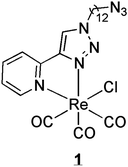 | ||
| Scheme 1 Chemical structure of the derivative, named 1. | ||
Spectrochemical images collected in the configuration employed at IRENI are diffraction limited. Diffraction-limited imaging is dependent on the wavelength of the probe light and on the NA of the objectives. The common Rayleigh criterion, which describes the ability of an imaging system to resolve two neighbouring point sources, is defined as d = 0.61λ/NA, where d is the minimum separation required to resolve the points, l is the probing wavelength, and NA is the numerical aperture of the imaging system. At this minimum separation, the contrast between two point sources is equal to 26.4%, and this contrast criterion is used in practice as a criterion to determine whether two objects are considered resolved according to the Rayleigh law. In the present case, Schwarzschild objectives are employed, leading to a different description that is not available in closed form, but a similar contrast criterion can be employed. Mid-infrared spectra are broadband; the wavelengths range from 2 to 10 μm, and thus it is impossible to collect high definition data for all wavelengths simultaneously if one uses only apertures and a single point detector. One must compromise either signal or spatial definition. Spatial oversampling is one strategy to obtain diffraction-limited, spatially resolved images across this bandwidth. The contrast resolution for confocal, dual aperture systems is predicted to be superior to one aperture systems, since the point spread function (PSF) is a multiplicative effect of two Schwarzschild objective PSFs, resulting in a narrower central peak and suppressed sidelobes at each wavelength.23 Reports of the contrast resolution determined from sufficiently spatially oversampled, raster-scanned data for confocal microscope optics with no apertures illuminated with a synchrotron beam were similar11,24 to the predicted values with dual apertures. For the widefield geometry employed in the present experiment, which is also apertureless, the pixel size, and thus spatial oversampling is based on the magnification of the objective that projects a certain area of the sample onto the detector pixels. Here the combination of spatial oversampling and NA influences the resolution of synchrotron-based widefield imaging. Results employing an array detector will be compared to results in the literature11,23,24 for synchrotron-based confocal, dual aperture, raster-scanning systems. We show that they are, within experimental noise, identical for deconvoluted image data and raster-scanned data from the confocal microscope, which is significant since samples are measured more quickly with the array detector. Analysis of spectrochemical images acquired from test samples and breast cancer cells using two distinct optical throughputs will be compared. In particular, two Schwarzschild objectives with varying magnification and NA (36×, 0.5 NA and 74×, 0.65 NA), both used in the Bruker Hyperion 3000 microscope, will be used to demonstrate this. While the highest magnification is likely desirable in most cases, experimental constraints sometimes require the inherently larger working distance (i.e. environmental controlled stages) and or the lower numerical aperture (i.e. tomography25) that are available with the lower magnification and lower NA objective. The comparison between the different magnifications and NAs allows an examination of the impact of spatial oversampling on the contrast resolution for both test samples and single breast cancer cells.
Chemical images obtained from hyperspectral cubes can be impacted by the quality of both the spatial and spectral information. Measurements of FTIR spectra of tissues and cells in transmission mode often produce spectra with inherent baseline effects and derivative shapes as a result of resonant Mie scattering. The scattering effect is particularly strong near edges of the cell or when features with a high contrast in refractive index are approximately the same size as the wavelength of the irradiating light. As a consequence, to provide a more quantitative analysis of effected cells, a resonant Mie scattering correction algorithm can be employed to removed these scattering effects from each spectrum in the hyperspectral cube.26–29 In this article we demonstrate the impact of employing a noise reduction algorithm based on a principal component analysis (PCA) followed by resonant Mie scattering spectral corrections and spatial deconvolution corrections to data for single cells. These proven algorithms are useful, since the biomarker is used in small concentrations and results in relatively weak absorption bands. The resulting data show both improved signal-to-noise for single pixel spectra, and higher contrast in the chemical images generated from the absorption features due to the biomarker specific functional groups.
2 Materials and methods
2.1 Sample preparation
MDA-MB-231 breast cancer cells obtained from the Human Tumour Cell Bank were used for the experiments. Both control and treated cells were processed in a similar way. They were seeded on CaF2 slides (deposited in 35 × 10 mm Petri dishes) in order to reach confluency after 48 h of incubation at 37 °C under an atmosphere of 95% air/5% CO2. Medium was removed and fresh growth medium (2 mL DMEM charcoal desteroided) was added to each flask of control cells. In the case of treated cells, 2 mL of a solution of 1 in fresh growth medium (25 μM prepared from a 5 × 10⁻³ M stock solution in DMSO) were added. The cells were incubated at 37 °C under an atmosphere of 95% air/5% CO2 for a period of 1 h. The media was then removed and the cells were washed twice with phosphate buffered saline (D-PBS, 1×, 2 mL). Cells were fixed by 4% paraformaldehyde (1.5 mL) for 8 minutes at room temperature and washed once with D-PBS (1×, 2 mL) and once with pure water (2 mL). Slides were then air-dried.2.2 IRENI FTIR spectroscopic imaging measurements
For the present investigations, each FTIR hyperspectral cube (x, y, A(ν)) was recorded in transmission mode using one of two optical setups: (1) a 74× objective (NA = 0.65) and a 20× condenser (NA = 0.65) or (2) a 36× objective (NA = 0.5) and a 15× condenser (NA = 0.4). The size of the FPA detector was set to 64 × 64 pixels, and 4096 individual spectra were measured simultaneously. With the former setup the measured area was 34 × 34 μm2 with an effective geometric pixel size of 0.54 × 0.54 μm2, and the latter setup measured an area of 70 × 70 μm2 with an effective geometric pixel size of 1.1 × 1.1 μm2. Spectra were acquired with a spectral resolution of 4 cm−1 and 128 scans. The measurement time for each sample was about 5 minutes. The resulting spectra and FTIR imaging data were evaluated by using the IR imaging software IRidys running under IGOR Pro 6.22.2.3 Spatial deconvolution applied to hyperspectral cubes
The deconvolution approach has been described in detail in a recent publication.30 Fast parallel algorithms have been implemented on graphics processing units (GPUs) for spatial deconvolution using NVIDIA's CUDA. NVIDIA CUDA has a library called CUFFT for efficiently computing discrete Fourier Transform.31 The library provides an interface for computing parallel fast Fourier transforms (FFTs), the most computationally expensive component of the algorithm, on GPU.32 This allows multiple transforms of any dimension to be executed in parallel in batches. The hyperspectral deconvolution algorithm involves the computation of FFTs three times for every wavelength in the data set, so efficiently parallelizing FFTs was significant in achieving a higher speed up. We also used Thrust library from NVIDIA to implement some other parts of the algorithm. Efficient implementations of the generic parallel reduction algorithms combined with transform iterators were used in particular to perform image scaling33 in parallel. Our GPU implementation achieved a speed up of 20× as compared to the previous implementation of algorithm on centralized processing unit (CPU) and Matlab. In brief, Fourier Transform (FT) based image deconvolution methods have been developed based on the measured and simulated PSFs, which have been measured and are distinct for each optical setup. Each image is deconvoluted independently and is subsequently rescaled by requiring equal transmitted light in the original and processed data. Finally, the data are reassembled in a hyperspectral cube.2.4 Spectral pre-processing
Spectral pre-processing was performed using Matlab Version 2012a (MathWorks Inc, Palo Alto, CA). Noise reduction based on PCA was applied to each hyperspectral dataset image to further improve the signal-to-noise ratio (SNR) for the individual spectra in each pixel. The process involves performing PCA, retaining a number of PCs and then reconstructing the original data from the remaining PCs. The appropriate number of PCs (here, 20 PCs) was chosen by examining the residual that is calculated from the original data matrix minus the reconstructed matrix.34Following PCA noise reduction, the RMieS algorithm was used to correct the data for resonant Mie (RMie) scattering effects. Generally, the algorithm takes a scatter free reference spectrum (Zref) (Matrigel, a commercial extra cellular matrix that contains all components expected for tissues/cells; nothing was added to the Matrigel standard to account for the biomarker) and uses this to reconstruct the raw spectrum (Zraw) to be corrected. This is done by assuming that Zraw is the superposition of Zref and a number of scattering curves that are determined from the broadband signal in each spectrum from the hyperspectral cube. The impact of the mixing of the real and imaginary part of the index of refraction due to the broadband Mie scattering effects is taken into account. The mathematical background of RMie scattering correction is described in detail elsewhere.26–28
3 Results and discussion
3.1 Spatial resolution of 36× (NA = 0.5) and 74× (NA = 0.65) objectives
In Fig. 1, we compare simulated resolutions based on the parameters determined from the experimental PSFs30 for both objectives with the experimentally-determined wavelength-dependent resolution of both objectives. First, we evaluated the experimentally measured PSFs to find the PSF contrast resolution (PSFCR), which is similar to the Rayleigh criterion for the Airy function, for the two objectives (solid lines, right axis). Two objects are considered resolved if the contrast difference between them exceeds 26.4%,35 so the full width at 73.6% maximum is the PSFCR. The determined PSFCR is wavelength dependent, and smaller for the 74× than for the 36× objective, particularly at the longest wavelengths. As expected, the NA of the objectives is the dominating factor in the experimental PSFCR, as described within the framework of the Rayleigh criterion. We compare these results to experimentally resolved USAF targets, both the original experimental (open circles) and deconvoluted (solid triangles), as described elsewhere.8,9,30,36 The original data (0.54 × 0.54 μm2 projected sample area per pixel) for the 74× magnification is only slightly above that predicted by the simulated PSFCRs. In contrast, the original data for the 36× show a poorer agreement with the predicted PSFCR, likely due to the coarser spatial sampling (1.1 × 1.1 μm2 projected sample area per pixel), employed in this configuration. In order to achieve optimal spatial resolution, the data must be sampled with at least 8 pixels spanning the dimension of the Airy disk for any given wavelength.35 Using the conventional Rayleigh criterion for the shortest wavelength in the mid-IR (2.5 μm), this corresponds to a pixel size no larger than 0.6 μm for the 74× objective, which is larger than the effective pixel size in the geometry employed here. Conversely, this sampling criterion for the 36× objective requires a pixel spacing no larger than 0.76 μm, which is smaller than the effective pixel size. Thus the optical setup for the 36× geometry is undersampled for wavelengths below 3.6 μm (2770 cm−1). Following deconvolution, however, both objectives yield resolutions exceeding the predicted PSFCR criterion, yet still retain their dependence on wavelength and NA as expected. This suggests that instrumental broadening is successfully removed through deconvolution, and a more faithful image is recovered in both cases. Importantly, this resolution is similar to and slightly exceeds that observed when using a confocal dual-aperture, raster scanning microscope.11,17,18 In sum, with the correct oversampling, and therefore projected sample pixel size that is matched to the NA of the objective, one achieves similar spatial resolution results for dual aperture confocal geometries.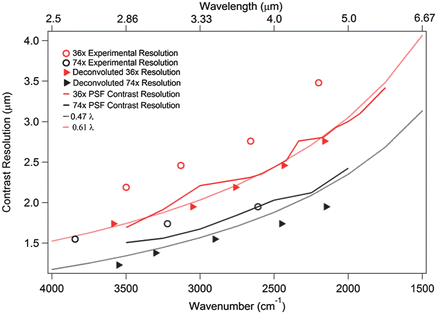 | ||
| Fig. 1 Predicted and experimental spatial resolutions of original and deconvoluted data. Contrast resolution (solid lines) of the PSF for the 36× (NA 0.5) and 74× (NA 0.6NA) objectives compared to the experimentally determined resolution limit for the 36× (NA 0.5) and 74× (NA 0.6NA) objectives before (open circles) and after (filled triangles) deconvolution, and with reported NA dependent trends for confocal, raster scanning resolution limits (dotted lines). | ||
3.2 Chemical images of control and labelled cells
In order to determine the distribution of 1 in a MDA-MB-231 cell, chemical images collected with the 74× objective were generated by integrating the area under individual absorption bands that are distinctive for the single cell and 1. The following integration parameters were used, (with straight baselines from the integration endpoints) Amide I: 1680–1612 cm−1, phosphate: 1260–1200 cm−1, A1 mode of 1: 2033–2013 cm−1 and E mode of 1: 1932–1890 cm−1.19 The Amide I and phosphate absorption bands are representative for the nucleus of the cell,37 while E- and A1-bands characterize the localization of 1. In Fig. 2, the visible (VIS) images and the integrated intensity of the Amide I, phosphate, E and A1 bands of a controlled and incubated cell are displayed. The contour colors vary between red (high intensity) to dark violet (low intensity), and the intensity corresponds to the integrated band intensity. For better comparison of the chemical images, constant scaling of the contour colors has been applied as a visualization tool for each individual functional group for displaying the differences of the controlled and incubated cell. Based on the chemical images of the cell incubated with 1 (Fig. 2B), it can be seen, that 1 is heterogeneously distributed in the cell and co-localized in regions of low Amide I and phosphate absorptions. Furthermore, to demonstrate the ability of IRENI to monitor variation of the spectra from pixel to pixel, stacks of single pixel data, spaced 2.2 micrometers apart from one another, along the dashed lines in Fig. 2B of the cell incubated with 1 are depicted in Fig. 3. In agreement with the integrated chemical images, specific absorption bands of 1 are predominant in the central region of the cell and are displaced slightly from the Amide-rich nuclear region.37 The images presented here are consistent with results previously described,19 since a perinuclear distribution of 1 was observed using SR-FTIR raster scanning. In addition imaging of cells labelled with both 1 and a fluorescent Golgi tracker inside MDA-MB-231 cells was performed, 1 being both luminescent and infrared active.19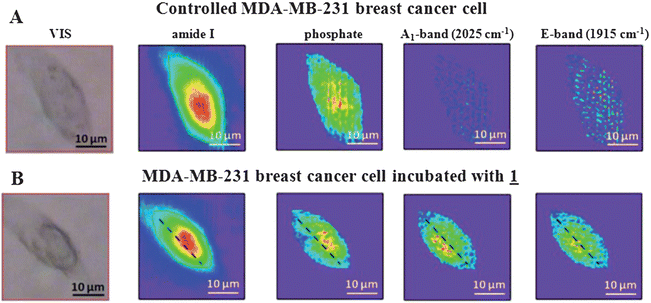 | ||
| Fig. 2 Visible and FTIR chemical images of MDA-MB-231 cells generated based on specific band integrations (Amide I: 1680–1612 cm−1, phosphate: 1260–1200 cm−1, A1-band: 2013–2033 cm−1 and E-band: 1890–1932 cm−1). (A) Top row: controlled cell, (B) bottom row: cell incubated with 1. | ||
 | ||
| Fig. 3 Stacks of spectra taken from individual pixels along the dashed line in Fig. 2B. The spectra come from pixels that are 2.2 μm apart. (A) shows the entire midinfrared spectral region, while (B) focuses on the region in which the specific bands of the biomarker can be found. | ||
3.3 Comparison of hyperspectral deconvolution of spectrochemical datasets of labelled cells with 36× (NA = 0.5) and 74× (NA = 0.65) objectives
In Fig. 4, we show integrated images of the protein specific (Amide I) and metal carbonyl (A1) functional groups within a second MDA-MB-231 incubated cell generated from both the raw and deconvoluted data sets taken with the 36× and 74× objectives No spectral pre-processing has been applied in this case. In the raw data taken with both objectives, the distribution of the Amide shows a slight displacement from the localization of the biomarker signature, which is discussed further below. Upon comparison of the raw and deconvoluted data from both objectives, it is clear that in all cases the deconvoluted images show sharper, more well-defined features with enhanced contrast.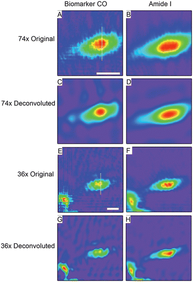 | ||
| Fig. 4 Original and deconvoluted chemical images of a breast cancer cell labelled with 1 taken with both 74× and 36× objectives. (A) and (B) show original chemical images (color scales: purple (low intensity) – red (high intensity)) of the cell as measured with the 74× objective generated by integrating under A1 mode of the biomarker (A), and Amide I (B). Scale bar in a is 20 μm. (C) and (D) show the results of deconvolution of the data used to generate (A) and (B). (E) and (F) show the analogous data of (A) and (B) as measured with the 36× objective. Scale bar in (E) is 20 μm. (G) and (H) show the results of deconvolution of the data used to generate (E) and (F). | ||
To more qualitatively address the effect of deconvolution on the data from both objectives, we compare intensity profiles through the same position of the cell for both datasets (Fig. 5). The location of the profile used for the 74× data set is indicated by the white line in Fig. 4A; all of the 74× profiles in Fig. 5 from the different functional groups are extracted from the exact same location. The location from which the profiles from the 36× data are extracted is shown by the white line in Fig. 4E. We first consider the relative distributions of the Amide I and the biomarker features within the cell as indicated by the original and deconvoluted 36× data (Fig. 5A). A comparison of the profiles from the Amide I chemical images from the original and deconvoluted datasets shows that the deconvolution results in a narrowing of the Amide distribution and a sharper edge at the periphery of the cell. Several informative quantities will be considered to evaluate the data. First, we will consider the effective spacing between the Amide and biomarker distributions as measured from the distance between the peak values of the Amide and biomarker profiles as shown in Fig. 5. Next, to quantify subcellular distances in this sample, we will consider, as a figure of merit, the distance between the peak value of the integrated intensity to the point where it reaches its minimum value (e.g., the peak-to-edge distances) for all of the profiles shown in Fig. 5. Lastly, to explore the relationship between error propagation and spatial oversampling, we will discuss a simple error analysis of the conclusions drawn on the Amide and biomarker distributions.
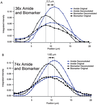 | ||
| Fig. 5 Line profiles through chemical images of the labelled cell shown in Fig. 4. (A) Original and deconvoluted line profiles of the Amide and biomarker chemical images shown in Fig. 4E–H. The profiles all come from the location indicated by the white line in Fig. 4E. The displacement between the Amide and biomarker signatures is measured to be 2.2 μm. (B) Original and deconvoluted line profiles of the Amide and biomarker chemical images shown in Fig. 4A–D. The profiles all come from the location indicated by the white line in Fig. 4A. The displacement between the Amide and biomarker signatures is measured to be 1.62 μm. | ||
We first evaluate the relative displacements between the Amide and biomarker signatures in the 36× and 74× datasets. In Fig. 5A, both the original and deconvoluted data sets show that the distance between the maximum values of the Amide and biomarker signals is 2 pixels, or 2.2 μm given the effective geometric pixel size at the sample plane for the 36× objective. The same quantity for the 74× objective in Fig. 5B is exactly 3 pixels, corresponding to an effective geometric distance of 1.62 μm at the sample plane. This discrepancy between the 2 objectives is a direct result of the coarser sampling of the 36× objective. While the difference between the two values is only 0.58 μm, this difference is a significant deviation of 35.8% from the Amide/biomarker separation measured between the 74× objective and corresponds to, nearly identically, the effective geometric size of one pixel using the 74× objective geometry (0.54 μm). Thus, these data indicate that sufficient spatial oversampling is critical in applications such as subcellular microscopy of biological specimens.
We now consider the peak-to-edge distances in the profiles shown in Fig. 5 to evaluate the change between raw and deconvoluted data for the two objectives. These distances for the Amide I and biomarker signatures before and after deconvolution are summarized in Table 1. We begin with Amide profiles derived from the 36× objective (Fig. 5A); the distance from the centre of the cell (the point of highest intensity in the Amide profile) to the bottom edge of the cell (where the intensity profile approaches its minimum value) is 7.8 μm in the original data set and 6.4 μm in the deconvoluted dataset, indicating a decrease of approximately 18% in the peak-to-edge spatial distribution of the Amide. In the case of the biomarker, the distance from the point of highest intensity of the biomarker to the bottom edge of the cell where the biomarker signal drops to zero changes from 10 μm in the original intensity profile to 7.7 μm in the deconvoluted profile. This corresponds to a decrease of 23% in the spatial distribution of the biomarker following the application of deconvolution. For the case of the 74× objective, shown in Fig. 4B, a similar trend showing a narrowing of the Amide and biomarker distributions is observed following deconvolution. In this case, the Amide peak-to-edge distance decreases from 8.7 μm in the original data to 6.55 μm in the deconvoluted data, corresponding to a change of 24%. Similarly, the peak-to-edge distance of the biomarker signature decreases from 10.8 μm in the raw data to 8.1 μm in the deconvoluted data, a change of 25%. These data give a direct demonstration of the impact of spatial oversampling on the effectiveness of deconvolution; the decrease in the effective distribution of the biomarker and Amide signatures shows a greater improvement for the case of the 74× oversampling than that of the 36×. For example, the change in peak-to-edge distance of the Amide I and biomarker distributions following deconvolution are 18% and 23%, respectively, for the 36× geometry. The same values for the 74× geometry are 24% and 25%; as before, these data indicate that the application of deconvolution has a greater impact in the case of sufficiently oversampled data. The relatively similar improvements between the Amide I and biomarker signatures in the 74× geometry upon deconvolution (24% and 25%) are consistent with the very similar wavelengths that the biomarker and Amide absorptions occur. With twice the pixel spacing of the 74× geometry, the 36× geometry has a measurement uncertainty that is 0.56 μm greater than that of the 74× geometry. This uncertainty, though small, can have a large impact on the assessment of distances and overall image detail when performing microscopy at the diffraction limit. This uncertainty is likely accountable for the comparatively large discrepancy in the changes in the peak to edge distances of the Amide I and biomarker distributions following deconvolution (18% and 23%, respectively).
We now discuss this measurement uncertainty in more detail. Consider first the measurement of the change in peak to edge distance in the Amide I distribution in the cell following deconvolution (decrease from 7.8 μm to 6.4 μm in the 36× data, Table 1). A measurement error of 1.1 μm in the peak to edge distances in the original and deconvoluted data will give a contribution of 4% toward the measurement error of the percent change in this distance, giving an error of 18 ± 18%. Similarly, the error in the peak to edge measurement of the biomarker in the 36× data is 23 ± 14%. The corresponding errors for the 74× data given an uncertainty of 0.54 μm are 24 ± 8% and 25 ± 6% for the Amide and biomarker changes, respectively. These data show that spatial oversampling has an important, measurable effect on both overall spatial resolution as well as measurement error, and underline the critical importance of spatial oversampling when performing diffraction-limited spectromicroscopy.
3.4 Impacts of spectral pre-processing of spectrochemical dataset
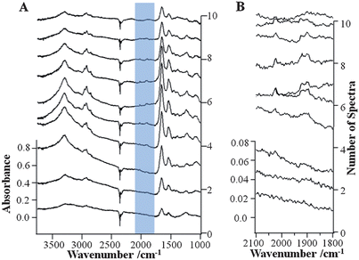
To further explore the effect of data processing methods on the spectral quality of the FTIR imaging data of the MBA-MD-231 cell incubated with 1, algorithms for PCA noise reduction and RMie scattering correction have been applied. The results of RMie scattering corrections for the PCA noise reduced hyperspectral cube of data of the MBA-MD-231 cell incubated with 1 are shown in Fig. 6A. To compare the spectral improvements due to PCA noise reduction and RMieS algorithms, individual FTIR spectra extracted from identical pixels in the respective hyperspectral cubes (see dashed black lines in Fig. 2B) are shown in Fig. 3A and 6A, respectively. When comparing these stacks of spectra, the corrected data (Fig. 6A) contain lower noise and have no baseline fluctuations. Fig. 6B depicts the stack of data with a portion of the spectral range and an enlarged absorption scale. Thus, further enhancement is observed in the absorption region (2100–1800 cm−1) of 1 for the corrected data in contrast to the raw FTIR spectra (Fig. 3B). The well-defined absorption bands that are indicative of the biomarker can be much more clearly evaluated in the corrected data in Fig. 6B. These results demonstrate the effect of applying the PCA noise reduction followed by RMie scattering correction algorithms, improving the quality of the spectral data and the absorption band-specific infrared images.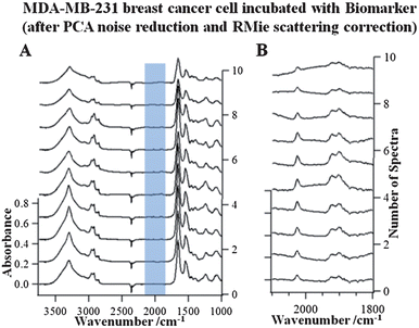 | ||
| Fig. 6 Stacks of extracted single FTIR spectra (spaced 2.2 micrometers apart from one another), along the dashed line indicated in the images in Fig. 2B of the PCA and RMie scatter-corrected data of the breast cancer cell incubated with 1 in the wavenumber range 3750–1000 cm−1 (A) and 2100–1800 cm−1 (B). | ||
3.5 Impacts of combining spectral pre-processing and spatial deconvolution of spectrochemical datasets
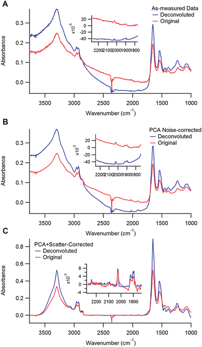
Since both the spatial and spectral corrections described in the previous sections impact the spatial contrast, it is important to explore the impact of combining these analytical approaches that are performed on individual frequency dependent images and on single pixel spectra. Thus, Fig. 7 shows a series of images of the biomarker distribution (generated from the A1 band) after applying various corrections. The images in the first column are derived from the original data, before (top) and after (middle) deconvolution. The images in the second column are obtained from PCA corrected data, before (top) and after (middle) deconvolution. The last column contains images generated by applying both PCA correction followed by RMie scattering correction algorithms. The final row of figures shows the overlapping distributions of the original or pre-processed (blue) and deconvoluted biomarker A1 (red) images to demonstrate the impacts on spatial contrast. In Fig. 8, spectra from the same pixel in all 6 original, pre-processed and deconvoluted data sets are shown. The location from which the spectra are extracted are indicated by the cross in Fig. 7B. The plots correspond to the similar columns in Fig. 7. Spectra plotted in red are original or pre-processed results, and blue are after deconvolution has been implemented. There are several conclusions about data analysis that can be drawn from Fig. 7 and 8. First note that the biomarker spectral signal is weak; thus, the signal to noise ratio is small compared to strong absorbers such as the Amide I absorption band. The results in the left-hand most column, showing the original and deconvoluted results of data with no spectral pre-processing, show that applying deconvolution to data with severe noise emphasizes both spectral and spatial features associated with low SNR due to the fact that noise becomes effectively blurred by Fourier Filtering. In addition, deconvolution can also enhance scattering contributions (more severe in this case than in the data in Fig. 4 and 5), which are indistinguishable from actual absorbance, resulting in more severe baselines (blue spectra in Fig. 8A). These anomalous baselines inevitably effect the quality of the resulting data and the potential of deconvolution to enhance spatial resolution and contrast. PCA-noise reduction, shown in Fig. 8C and F, improves the spectral SNR and contrast in the images; however, the deconvolution still enhances the scattering baseline. Finally, applying the RMie scattering correction to the PCA corrected data allows for much greater improvement in the deconvolution process. First the images show a larger contrast difference between the before and after deconvolution; the final blue/red overlapped image indicates a much narrower spatial distribution of the biomarker signature following deconvolution. Also, the baseline artefacts are clearly reduced (spectra in Fig. 8C), and not enhanced with the deconvolution step.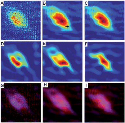 | ||
| Fig. 7 Effect of spectral pre-processing on deconvoluted chemical images of the localization of 1 (A1 mode). The top (A–C) row indicates original data with or without pre-processing. The middle row (D–F) shows the results of deconvolution on the corresponding datasets in the top row. The bottom row (G–I) shows red/blue overlays of the previous two rows to demonstrate the impact of deconvolution; original data is displayed as red and deconvoluted data as blue. The columns are aligned such that the left column (A, D, and G) has no spectral pre-processing, the middle column (B, E, and H) has been treated with PCA noise-reduction, and the right column (C, F, and I) has been treated with PCA noise-reduction followed by RMie scatter-correction. | ||
 | ||
| Fig. 8 Original (red) and deconvoluted (blue) spectra from the datasets in Fig. 7. Spectra are extracted from the pixel indicated by the cross in Fig. 7B. (A) shows the results for spectra from Fig. 7A and D (no pre-processing, deconvolution applied to as-measured data). (B) shows the results for spectra from Fig. 7B and E (PCA noise-correction applied prior to deconvolution) and (C) shows the results for spectra from Fig. 7C and F (PCA noise-correction and RMie scatter-correction applied prior to deconvolution). The insets show the spectral region from 1800–2300 cm−1 to illustrate the importance of the corrections for the weak biomarker signatures. | ||
These results demonstrate the effect of applying the PCA noise reduction followed by RMie scattering correction algorithms and spatial deconvolution, in a sequence with deconvolution applied last, all improve the quality of the spectral data and the absorption band specific, infrared images.
4 Conclusions
Synchrotron based widefield FTIR microspectroscopy studies the imaging capabilities of different objectives with different demonstrate impact of NA, spatial oversampling and PSF deconvolution on spatial resolution. Measurements of incubated MDA-MB-231 breast cancer cells demonstrate the ability to create chemically specific images with high spatial contrast and detect a low concentration exogenous metal-CO derivative 1 with a weak infrared signature at the single cell level. Images from distinct functional groups show that 1 is partly overlaid with a region rich in Amide and phosphate absorptions, which is consistent with previous correlative infrared and luminescence studies where we demonstrated 1 had a perinuclear distribution attributed to the Golgi apparatus.19 Different magnification and spatial oversampling conditions provide direct comparisons between these optical choices. The original data, which is rapidly collected with two different objectives, has only slightly poorer spatial resolution to reported values for data collected with raster-scanned, confocal optics with similar NA. Nevertheless, in both cases, PSF deconvolution can be applied to the data to remove instrumental broadening and improve the spatial resolution to the reported values for confocal optics with similar NA, and simultaneously improve spectral purity of the hyperspectral cube. Spatial oversampling is also critical for achieving optimum spatial resolution; our results demonstrate that high spatial oversampling coupled with large NA promotes greater impact in the results of deconvolution and lower measurement uncertainty. Applying spatial deconvolution to hyperspectral cubes has been successful, improving the spatial contrast of the images and SNR of the spectra. In addition, spectral pre-processing such as PCA-based noise reduction and RMie scattering corrections were applied to improve the SNR and remove the phenomenon of resonant Mie scattering in the data sets, respectively. These improvements were demonstrated by comparing the FTIR images and the extracted single-pixel spectra before and after the correction procedures.Acknowledgements
The authors are gratefully acknowledging Dr Caryn Hughes (University of Manchester, UK) for helpful discussions particularly on the data analysis. IRENI was developed under the grant MRI-DMR-0619759. This work was supported by the NSF under grant CHE-1112433. The SRC is funded by UW-Madison and UW-Milwaukee. CP and SC want to acknowledge ENS for PhD fellowship for SC and GIS-groupe français de chimie bioinorganique for financial support.Notes and references
- C. Sandt, J. Frederick and P. Dumas, J. Biophotonics, 2013, 6, 60–72 CrossRef CAS.
- S. W. Fogarty, Patel II, J. Trevisan, T. Nakamura, C. J. Hirschmugl, N. J. Fullwood and F. L. Martin, Analyst, 2013, 138, 240–248 RSC.
- M. J. German, A. Hammiche, N. Ragavan, M. J. Tobin, L. J. Cooper, S. S. Matanhelia, A. C. Hindley, C. M. Nicholson, N. J. Fullwood, H. M. Pollock and F. L. Martin, Biophys. J., 2006, 90, 3783–3795 CrossRef CAS.
- H. Y. N. Holman, E. Wozei, Z. Lin, L. R. Comolli, D. A. Ball, S. Borglin, M. W. Fields, T. C. Hazen and K. H. Downing, Proc. Natl. Acad. Sci. U. S. A., 2009, 106, 12599–12604 CrossRef CAS.
- H. Y. N. Holman, H. A. Bechtel, Z. Hao and M. C. Martin, Anal. Chem., 2010, 82, 8757–8765 CrossRef CAS.
- E. C. Mattson, H. H. Pu, S. M. Cui, M. A. Schofield, S. Rhim, G. H. Lu, M. J. Nasse, R. S. Ruoff, M. Weinert, M. Gajdardziska-Josifovska, J. H. Chen and C. J. Hirschmugl, ACS Nano, 2011, 5, 9710–9717 CrossRef CAS.
- Z. Q. Li, G. M. Wang, N. Sai, D. Moses, M. C. Martin, M. Di Ventra, A. J. Heeger and D. N. Basov, Nano Lett., 2006, 6, 224–228 CrossRef CAS.
- M. J. Nasse, M. J. Walsh, E. C. Mattson, R. Reininger, A. Kajdacsy-Balla, V. Macias, R. Bhargava and C. J. Hirschmugl, Nat. Methods, 2011, 8, 413–U458 CrossRef CAS.
- M. J. Nasse, E. C. Mattson, R. Reininger, T. Kubala, S. Janowski, Z. El-Bayyari and C. J. Hirschmugl, Nucl. Instrum. Methods Phys. Res., Sect. A, 2011, 649, 172–176 CrossRef CAS.
- N. S. Marinkovic, R. Huang, P. Bromberg, M. Sullivan, J. Toomey, L. M. Miller, E. Sperber, S. Moshe, K. W. Jones, E. Chouparova, S. Lappi, S. Franzen and M. R. Chance, J. Synchrotron Radiat., 2002, 9, 189–197 CrossRef CAS.
- E. Levenson, P. Lerch and M. C. Martin, Infrared Phys. Technol., 2006, 49, 45–52 CAS.
- S. Lupi, A. Nucara, A. Perucchi, P. Calvani, M. Ortolani, L. Quaroni and M. Kiskinova, J. Opt. Soc. Am. B, 2007, 24, 959–964 CrossRef CAS.
- T. Ducic, S. Quintes, K. A. Nave, J. Susini, M. Rak, R. Tucoulou, M. Alevra, P. Guttmann and T. Salditt, J. Struct. Biol., 2011, 173, 202–212 CrossRef CAS.
- D. McNaughton and B. R. Wood, Aust. J. Chem., 2012, 65, 218–228 CrossRef CAS.
- P. Dumas, F. Polack, B. Lagarde, O. Chubar, J. L. Giorgetta and S. Lefrancois, Infrared Phys. Technol., 2006, 49, 152–160 CAS.
- P. Heraud and M. J. Tobin, Stem Cell Res., 2009, 3, 12–14 CrossRef.
- C. Policar, J. B. Waern, M. A. Plamont, S. Clède, C. Mayet, R. Prazeres, J. M. Ortega, A. Vessieres and A. Dazzi, Angew. Chem., Int. Ed., 2011, 50, 860–864 CrossRef CAS.
- M. Salmain and A. Vessières, in Bioorganometallics, Wiley-VCH Verlag GmbH & Co. KGaA, 2006, pp. 263–302 Search PubMed.
- S. Clède, F. Lambert, C. Sandt, Z. Gueroui, M. Refregiers, M. A. Plamont, P. Dumas, A. Vessieres and C. Policar, Chem. Commun., 2012, 48, 7729–7731 RSC.
- S. Clède, F. Lambert, C. Sandt, Z. Gueroui, N. Delsuc, P. Dumas, A. Vessières and C. Policar, Biotechnol. Adv., 2013, 31, 393–395 CrossRef.
- I. S. Butler, R. P. Kengne-Momo, G. Jaouen, C. Policar and A. Vessieres, Appl. Spectrosc. Rev., 2012, 47, 531–549 CrossRef CAS.
- M. Patra and G. Gasser, ChemBioChem, 2012, 13, 1232–1252 CrossRef CAS.
- G. L. Carr, Rev. Sci. Instrum., 2001, 72, 1613–1619 CrossRef CAS.
- E. Levenson, P. Lerch and M. C. Martin, Infrared Phys. Technol., 2008, 51, 413–416 Search PubMed.
- M. C. Martin, C. Dabat-Blondeau, M. Unger, J. Sedlmair, D. Parkinson, H. A. Bechtel, B. Illman, J. M. Castro, M. Keiluweit, D. Buschke, B. Ogle, M. J. Nasse and C. J. Hirschmugl, Nat. Methods, 2013 Search PubMed , accepted.
- P. Bassan, A. Sachdeva, A. Kohler, C. Hughes, A. Henderson, J. Boyle, J. H. Shanks, M. Brown, N. W. Clarke and P. Gardner, Analyst, 2012, 137, 1370–1377 RSC.
- P. Bassan, A. Kohler, H. Martens, J. Lee, H. J. Byrne, P. Dumas, E. Gazi, M. Brown, N. Clarke and P. Gardner, Analyst, 2010, 135, 268–277 RSC.
- P. Bassan, A. Kohler, H. Martens, J. Lee, E. Jackson, N. Lockyer, P. Dumas, M. Brown, N. Clarke and P. Gardner, J. Biophotonics, 2010, 3, 609–620 CrossRef CAS.
- B. J. Davis, P. S. Carney and R. Bhargava, Anal. Chem., 2010, 82, 3487–3499 CrossRef CAS.
- E. C. Mattson, M. J. Nasse, M. Rak, K. M. Gough and C. J. Hirschmugl, Anal. Chem., 2012, 84, 6173–6180 CrossRef CAS.
- NVIDIA CUDA Compute Unified Device Architecture Programming Guide, V 4.2, 04/16/2012, http://docs.nvidia.com/cuda/cuda-c-programming-guide/.
- CUDA Toolkit 4.2 CUFFT Library Programming Guide, March 2012,http://docs.nvidia.com/cuda/cufft/index.html.
- NVIDIA Thrust quick start guide v5.0, October 2012, http://docs.nvidia.com/cuda/thrust/index.html.
- P. C. Gillette and J. L. Koenig, Appl. Spectrosc., 1982, 36, 535–539 CrossRef CAS.
- E. H. K. Stelzer, J. Microsc., 1998, 189, 15–24 CrossRef.
- E. C. Mattson, M. Unger, B. Manandhar, Z. Alavi and C. J. Hirschmugl, J. Phys.: Conf. Ser., 2013, 425, 142001 CrossRef.
- E. Gazi, J. Dwyer, N. P. Lockyer, J. Miyan, P. Gardner, C. Hart, M. Brown and N. W. Clarke, Biopolymers, 2005, 77, 18–30 CrossRef CAS.
Footnotes |
| † Contributed equally. |
| ‡ Present address: CETICS Healthcare Technologies GmbH, D 73728 Esslingen am Neckar, Germany. |
| This journal is © The Royal Society of Chemistry 2013 |