 Open Access Article
A compact high resolution ion mobility spectrometer for fast trace gas analysis
Ansgar T.
Kirk
*,
Maria
Allers
,
Philipp
Cochems
,
Jens
Langejuergen
and
Stefan
Zimmermann
Leibniz University Hannover Institute of Electrical Engineering and Measurement Technology, Dept. of Sensors and Measurement Technology, Appelstr. 9A, 30167 Hannover, Germany. E-mail: kirk@geml.uni-hannover.de; Tel: +49 511 762 4672
First published on 23rd April 2013
Abstract
Drift tube ion mobility spectrometers (IMS) are widely used for fast trace gas detection in air, but portable compact systems are typically very limited in their resolving power. Decreasing the initial ion packet width improves the resolution, but is generally associated with a reduced signal-to-noise-ratio (SNR) due to the lower number of ions injected into the drift region. In this paper, we present a refined theory of IMS operation which employs a combined approach for the analysis of the ion drift and the subsequent amplification to predict both the resolution and the SNR of the measured ion current peak. This theoretical analysis shows that the SNR is not a function of the initial ion packet width, meaning that compact drift tube IMS with both very high resolution and extremely low limits of detection can be designed. Based on these implications, an optimized combination of a compact drift tube with a length of just 10 cm and a transimpedance amplifier has been constructed with a resolution of 183 measured for the positive reactant ion peak (RIP+), which is sufficient to e.g. separate the RIP+ from the protonated acetone monomer, even though their drift times only differ by a factor of 1.007. Furthermore, the limits of detection (LODs) for acetone are 180 pptv within 1 s of averaging time and 580 pptv within only 100 ms.
Introduction
Drift tube ion mobility spectrometers (IMS) characterize different substances by ionizing analytes and studying the motion of the ions through a so-called drift gas under the influence of an electric field. IMS have earned a reputation for providing extremely good detection limits in the low ppb- and even ppt-range in a short period of time, usually in less than a second, and at relatively low cost.1,2 These advantages have led to their widespread use as fast detectors for explosives, drugs, chemical warfare agents, or other hazardous substances.3,4 In the past years, many other applications in science and industry have been explored. Examples are bioanalysis,5–7 quality control for food,8,9 and medication10,11 or polymer characterisation.12However, ion mobility spectrometers are limited in their applications as they are generally considered as low-resolution devices. Typical products that are commercially available achieve resolutions defined as the ratio of the drift time tD and the full width at half maximum (FWHM) of 20–60.13 This can lead to unwanted false negatives or positives as the measurement uncertainty for a peak position may be too high to obtain an unambiguous identification. Furthermore, small peaks may be masked by larger peaks of similar mobilities or the sum of two peaks of similar height may appear as a single peak of intermediate mobility.
Therefore, the improvement of the analytical performance of IMS both through operational and instrumental developments has been an ongoing task over the past decades. Operational improvements may include techniques such as post-processing of the acquired spectra to separate conjoined peaks,14 sweeping of the drift voltage for drift tubes with a mobility dependent separation performance,15 or using ion–ion recombination dynamics as an orthogonal pre-separation method.16 However, such techniques are always limited by the overall performance of the drift tube itself.
The typical instrumental approach to achieve higher resolution is the construction of longer drift tubes, mainly used in IMS-MS applications. These large laboratory devices can reach a significantly higher resolution than commercial instruments. Values of 172 for single-charged17 and 240 for multiple charged ions,18 which are typically easier to separate, have been reported for a 63 cm long drift tube. For multiple charged ions, the so-called ion cyclotron ion mobility spectrometer, which uses a circular drift tube with a length of about 180 cm to prolong the ion flight as long as ion storage is possible,19 has achieved resolutions up to 400. It however acts as an ion filter and therefore sweeping different cycle frequencies is required to measure the whole spectrum. In addition to this, signal intensities are low due to heavy ion losses,20 leading to long acquisition times. All these devices have dimensions too large for portable instruments. Furthermore, such laboratory systems have higher manufacturing cost limiting widespread field use. A compromise between the current commercial designs and much larger laboratory prototypes is available in the form of a 26 cm long resistive glass tube design.21 This ion mobility spectrometer was reported to reach resolutions between 60 and 150, primarily depending upon the used ion source.
Here we present a refined theory of IMS operation that allows us to design compact drift tube IMS with both very high resolution and extremely low limits of detection. Based on this theory, a 10 cm short drift tube IMS with a resolution of 183 – measured for the positive reactant ion peak (RIP+) – and limits of detection within the low pptv-range has been developed. Furthermore, with multi-physics simulations a good understanding of the ions' motion inside the drift tube has been developed over the past few years.22,23 With such tools at hand, it seems possible to further optimize our IMS to reach resolutions above 200.
Theoretical section
Basic theory
In order to understand how the construction of a compact high resolution IMS can be possible, it is first necessary to recognize which factors determine the resolution of a drift tube and how they interact with each other. For this purpose, a known analytical model of the measurement process in an ion mobility spectrometer is used. It is assumed that, at a certain point in time, an ion packet with Gaussian shape and an initial temporal width wInj is injected into the drift region. The distance to the detector is defined as the drift length L and the voltage applied across is the drift voltage UD. The ions travel with a drift velocity proportional to their ion mobility K and undergo broadening by diffusion, which is described using the absolute temperature T, Boltzmann's constant kB and the elementary charge e. The quality of the achieved separation is usually expressed by the resolution R, which is defined as the ratio of the drift time tD and the full width at half maximum (FWHM) upon arrival at the detector. In the following we define w0,5 = FWHM. Using the well-known terms for tD and w0,5,24eqn (1) can be derived. This equation has been extensively used in the past to analyse the resolution of IMS.25 | (1) |
It is obvious that eqn (1) must reach a maximum at a certain drift voltage, as the resolution decreases due to the increasing peak broadening by diffusion at lower drift voltages and the increasing influence of the initial temporal width of the ion packet at higher drift voltages. By calculating the partial derivative of eqn (1) with respect to UD, eqn (2) can be found. It specifies the optimum voltage Uopt, at which the said resolution maximum is reached. Substituting this result into eqn (1) yields eqn (3), which describes the maximum achievable resolution Ropt for a certain drift tube IMS. Using this quantity for further analysis instead of eqn (1) simplifies calculations and allows a better understanding of the complex interactions between the different other parameters affecting the resolution.
 | (2) |
 | (3) |
For constant operating conditions, the achievable resolution is only determined by the ratio of L2/wInj. Therefore, the resolution can be kept constant even for short drift tube lengths as long as sufficiently small ion packets are injected.
Increasing the drift length to achieve higher resolution is of course much easier, but contradicts our goal of compact IMS. The required voltage to achieve a certain resolution is proportional to its square, independent of the length of the drift tube, as Ropt depends on L2/wInj and Uopt depends on L4/wInj2. Thus, high resolution IMS will always require high drift voltages. It should be also noted that the temporal ion packet width at the detector is directly proportional to the initial temporal ion packet width if the optimum drift voltage is applied. This relationship can be derived by evaluating the denominator of eqn (1) for the voltage specified by eqn (2). The result is given in eqn (4), which is extremely helpful, as it facilitates many of the following calculations.
 | (4) |
Amplifier, ion loss, and SNR
Although the present model offers a useful and accurate prediction for the processes inside an ion mobility spectrometer, it suffers from two shortcomings. First, no equation to analyse the signal-to-noise-ratio is integrated into the model. Second, the resolution is predicted for the ion current peak at the detector, but the measured signal is the output voltage after amplification. Usually the equivalent input noise generated by the high-gain transimpedance amplifiers used in IMS applications is inversely proportional to their rise time,26 meaning that a compromise between these quantities is necessary. Thus, it can be expected that the amplifier significantly influences both the resolution and the signal-to-noise-ratio of the instrument. Consequently, the present model for evaluating the IMS resolution must be extended to include the effects of a non-ideal amplifier. The frequency spectrum of a Gaussian peak is given by eqn (5) and is a Gaussian peak itself, with a standard deviation proportional to the temporal half width w0,5. Fourier transform was carried out using the frequency f. Multiplying the peak's frequency spectrum with the amplifier's transfer function leads to the output spectrum, which can be transformed back to the time domain, where peak distortion becomes visible.27 Calculating the resulting distortion this way is possible, but not feasible, since it cannot be expressed by a simple equation to be integrated into an applicable model for predicting resolution and SNR. | (5) |
However, a relationship which can be used to derive a useful approximation for the peak distortion and its effect on resolution is shown in Fig. 1. Here, the resolution after amplification by a non-ideal amplifier is compared to that resulting from a longer initial pulse width.
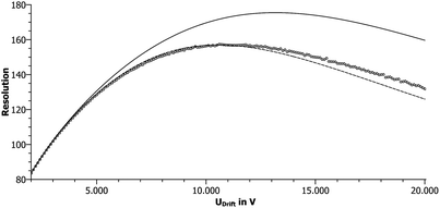 | ||
| Fig. 1 Resolutions for wInj = 10 μs (solid line), wInj = 14 μs (dashed line) and wInj = 10 μs filtered by a PT1 with fg = 32 kHz (circles). | ||
Close to the resolution maximum, the agreement between the two curves is excellent. It should be noted that this similarity exists for all stable amplifiers. Therefore it is possible to transfer eqn (1)–(4) to a refined model by replacing the initial temporal ion packet width wInj with a longer temporal width also accounting for the amplifier. wInj should still be used whenever an effect directly related to the injection, like ion loss at the shutter grid, is analysed. Therefore, we define a minimum temporal width wMin, as it represents the minimum temporal half width at the detector that a certain drift tube–amplifier combination can achieve.
When combining different contributors to the width of a Gaussian peak, as for example the initial width wInj and the diffusion term in the denominator of eqn (1), geometric addition is used. Therefore, wMin is defined by eqn (6) as the geometric addition of wInj and the additional quantity wAmp, which describes the influence of the amplifier.
 | (6) |
For calculating wMin from readily available data, it is necessary to express wAmp in terms of a measurable property of the transimpedance amplifier. As the frequency response is too complex to derive a direct relationship, the rise time tr 10–90 was chosen. Using simulations, a large number of different combinations of amplifiers and initial ion packet widths were analysed. For each combination, the exact resolutions after amplification were calculated numerically for several drift voltages and a least-squares-fit was applied to determine the respective value of wAmp which results in the smallest deviation between the exact results and those approximated using eqn (6). As shown in Fig. 2, the necessary value of wAmp is nearly proportional to the rise time of the amplifier and therefore inversely proportional to its noise σNoise, yielding eqn (7) and (8). These relationships can be used to simplify the analysis of resolution and signal-to-noise-ratio for the complete system including the drift tube and transimpedance amplifier.
| wAmp = 0.9tr 10−90 | (7) |
 | (8) |
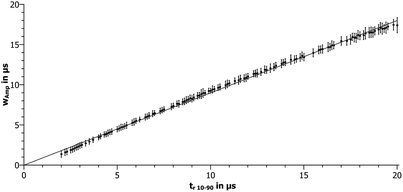 | ||
| Fig. 2 Relationship between wAmp and tr 10–90 obtained from a simulation. Error bars indicate standard deviation. The solid line represents a linear least-squares-fit. | ||
The fact that the additional broadening is lower than the rise time of the amplifier can be attributed to the Gaussian shape of the peak. The spread between the resulting values of wAmp for a single value of tr 10−90 in Fig. 2 is caused by the fact that the rise time alone cannot attribute for all the subtleties of the frequency response.
Knowing the half-width at the detector and the noise, the only missing quantity for calculating the signal-to-noise-ratio is the peak area or total charge Q. It is determined from the amount of charge injected into the drift tube and the subsequent ion losses during the drift. As the drift time scales proportional to L2, when a constant drift voltage is applied, no significant radial diffusion is expected to occur inside a compact drift tube. Therefore, the charge at the detector should be similar to the injected amount of charge. This assumption corresponds well with simulation results.23 For the calculation of the injected charge, it should be noted that our drift tube design is not based on a Bradbury–Nielsen-shutter, but switches a high drift field inside the ionization region for ion packet injection. As the transparency of the grid to ions strongly depends on the ratio of the electric drift field strength and the injection field strength,28 the number of ions injected through such a shutter will increase proportionally to the drift field. Furthermore, the shorter and higher the pulse to reach a minimum initial ion packet width, the lower the number of ions injected. Taking into account that shorter drift times allow for higher number of averages n at the same time, the SNR can be estimated by eqn (9), with Q/w0,5 representing the peak height and  representing the remaining noise after averaging. The charge Q is determined by the field-dependant injection ion loss as described before and is therefore proportional to wInjED, while the number of averages n is inversely proportional to the drift time tD.
 | (9) |
Using the relationships between the different factors, which are known from eqn (1)–(4) and (8) and the fact that tD ∼ L/ED, eqn (9) can be simplified to eqn (10). It is interesting to note that there is no direct influence of the drift length on the SNR, as the effects of changing field strengths and averaging compensate each other.
 | (10) |
The normalised resolutions and SNR calculated using eqn (3), (6) and (10) for different ratios wInj/wAmp are plotted in Fig. 3. In order to achieve the maximum SNR, both widths should be chosen to be identical. The maximum resolution for a given temporal width is achieved, when the contribution of the other width becomes negligible. This however should not be misinterpreted, as it also means that only a fraction of the maximum possible resolution related to the shorter width will be obtained. When the resolution is normalized to the maximum possible resolution related to the shorter width, it becomes obvious that the best resolution efficiency is also reached for equal widths. Interestingly, a reduction of the initial width can lead to an increase of the SNR, as the IMS is shifted to a more favourable operating point. In addition, equal temporal widths will cause the SNR to remain constant for all possible values. Thus, the SNR is independent from the initial ion packet width. In other words, the initial ion packet width can be reduced without loss of detection limit or increasing measurement time. This is an extremely important observation, as it provides the basis for the construction of a compact high resolution ion mobility spectrometer without sacrificing the excellent limits of detection.
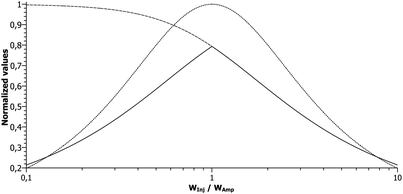 | ||
| Fig. 3 Normalized SNR (dotted) and resolution normalized to the maximum resolution possible based on the amplifier width (dashed) or related to the shorter of the two widths (solid). | ||
To demonstrate the above findings, a peak of an ion mobility spectrometer with a resolution of 60 and a SNR of 50 is shown in panel (A) of Fig. 4. Aiming at improving this resolution above 180 by the presented approach, both the initial ion packet width wInj and the amplifier width wAmp, which corresponds to the amplifier rise time tr 10−90, must be reduced by a factor of 27 according to eqn (3) and (6). At the same time, the applied drift voltage and therefore the electric drift field are increased by a factor of 9 according to eqn (2). The increased drift field strength results in both proportionally less ion loss upon ion packet injection and shorter drift times allowing for more averages at the same time, thus mitigating the negative effects of the reduced widths. In fact, the charge injected into the drift tube will decrease by a factor of 27/9 = 3 and the standard deviation of the noise will increase by a factor of  , thus resulting in a total decrease of the SNR by a factor of 27. However, according to eqn (4), the temporal half width at the detector will also decrease by a factor of 27, which in turn increases the SNR by a factor of 27. As these three effects compensate each other, the SNR remains constant as shown in panel (B) of Fig. 4. Despite the increased noise and the reduced amount of charge reaching the detector, the taller peak results in a constant SNR.
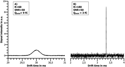 | ||
| Fig. 4 Peaks for different measurement parameters. Both panels show a 2 ms wide excerpt from the respective spectra. In (B) the initial ion packet and amplifier widths have been reduced by a factor of 27 compared to (A), and the voltage has been readjusted according to eqn (2). | ||
Scaling rules
Based on the predictions of the extended model, both very high resolution and excellent limits of detection can be achieved in a compact IMS at the same time. However, miniaturization and subsequent scaling of parameters give rise to other factors, which are negligible in longer drift tube designs. Thus, these phenomena must be evaluated in order to achieve the desired high resolution. To do so, the relationships presented in Table 1 can be easily derived from eqn (1)–(4). They present a useful guideline on how conditions inside the drift tube will change when ion mobility spectrometers are scaled down to a size suitable for portable instruments while keeping the resolution constant.| Quantity | Symbol | Scaling |
|---|---|---|
| Injection width | w Inj | ∼L2 |
| FWHM at the detector | w 0,5 | ∼L2 |
| Electric drift field strength | E D | ∼L−1 |
| Drift voltage | U D | Not required |
| Drift time | t D | ∼L2 |
Field inhomogeneities
A well-known problem in drift tube designs is the negative effect of drift field inhomogeneities on the resolution and, due to the constant amount of charge, also signal intensity. Eqn (11) describes a simple model for field inhomogeneities: Two ions of the same mobility travel from one equipotential line to another, traversing the distance l and the voltage EDl. Prolonging one of the flight paths by Δl results in a relative peak broadening ΔtD/w0,5. | (11) |
This indicates the following. When a drift tube is scaled down and a constant specified resolution is demanded, the effect of field inhomogeneities will grow inversely proportional to the drift length. We used multi-physics simulations to evaluate different drift tube geometries and to find an optimum design.
Mirror charges
The electric field of an ion packet traveling inside the drift tube will induce a mirror charge of opposite polarity on any metal surface, including the detector. This causes charges to gradually flow onto the Faraday plate as the ions move closer, thus broadening the peak. To prevent this, a so-called aperture grid is usually placed in front of the detector to shield the detector from the electric field. This grid however does not provide perfect shielding, as it is neither a continuous metal surface nor infinitely close to the detector. As the width of the ion packet decreases in proportion to the square of the reduced drift lengths, the shielding must be improved likewise to prevent negative effects on the resolution. This can be accomplished by moving the Faraday plate closer to the aperture grid or increasing the voltage between the detector and the aperture grid in order to minimize the time ions spend in this unshielded region. Another possible approach is decreasing the mesh size of the grid to minimize field penetration. Unfortunately, all of these changes also increase the susceptibility of the device to mechanical vibrations, requiring a mechanically more stable construction of the detector unit.Coulomb repulsion
Mutual Coulomb repulsion between the ions of a moving ion packet can lead to further broadening and loss of resolution. While the associated equations are too complex to find an exact analytical solution, a good approximation is possible by applying Gauss' law to the charge cloud, assuming a symmetrical distribution.29 Based on this, the force exerted on the cloud's surface and its resulting displacement over time can be calculated. In our design, a radioactive tritium source with a diameter of 10 mm is employed to minimize the charge density while maintaining a high absolute charge. Due to the large ionization area and the short initial peak width, the ion cloud can be well approximated by an infinitely thin disk. Gauss' law then yields a constant field EIon in eqn (12) throughout the drift, which only depends on the ratio of total charge Q to surface area A and the free space permittivity ε0. | (12) |
Decreasing the amount of travelling charge and increasing the drift velocity vD both lead to a reduction of the spatial displacement, resulting in a lower relative temporal half width Δw0,5/w0,5 caused by Coulomb repulsion, as shown in eqn (13).
 | (13) |
Coulomb repulsion should therefore be less critical when scaling down ion mobility spectrometers while keeping the resolution constant. This effect could also promote ionization sources with adjustable intensity, like corona discharge,28,30 or non-radioactive electron emitters,31 to achieve higher signal intensities and therefore lower limits of detection.
High field effects and breakdown
Finally, high-field effects have to be considered, which are field dependent ion mobilities leading to drift velocities not directly proportional to the electric field strength, and the possibility of a gas discharge. Both effects become increasingly important when miniaturizing IMS due to growing field strengths. The high-field region is expected at voltages high enough to gain energy from the electric field comparable to the thermal energy of an ion. Estimations in the literature are sometimes as low as 2 Td,2 but in FAIMS usually no measurable changes in mobility could be observed below 10 Td.32,33 For operating conditions of 1013 mbar and 298.15 K, this would result in electric field strengths between 50 V mm−1 and 250 V mm−1. Such electric fields are possible in compact IMS, so that high-field effects on the ion mobility need to be considered. Both values are significantly lower than the field strengths required for a gas discharge, which is estimated to be 3000 V mm−1 for the mentioned operating conditions. However, certain metal parts, particularly the guard rings, are usually separated by smaller gaps than the corresponding drift length inside the drift tube, resulting in accordingly higher local field strengths. Therefore the Paschen curve has to be considered upon designing the drift tube to ensure that all gaps are either small or large enough.Experimental section
IMS design
Based on the considerations presented in the theoretical section of this paper, a compact high resolution drift tube was constructed. The basic layout is similar to typical drift tube designs, consisting of an ionization region, a drift region and a shielded Faraday plate as the ion detector. A schematic of our setup is shown in Fig. 5 and its operating parameters are summarized in Table 2. Reactant ion generation is initiated by electron emission from a radioactive H3-source. A metallic grid divides the ionization region from the drift region and ion injection is controlled by pulsing the drift field inside the ionization region. A resistive voltage divider is used for applying the drift field. The whole instrument is sealed inside a surrounding PEEK tube, which prevents contamination and directs the flow of the drift gas. Purified air is used as the sample carrier and drift gas.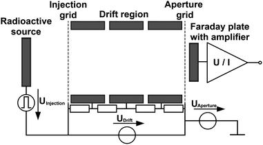 | ||
| Fig. 5 Schematic diagram of the drift tube. | ||
| Parameter | Value |
|---|---|
| Drift length | 98 mm |
| Drift region diameter | 15 mm |
| Source diameter | 10 mm |
| Source activity | 300 MBq |
| Injection voltage | 250…2000 V |
| Injection time | 5…350 μs |
| Repetition rate | 44 Hz |
| Drift voltage | 4…18 kV |
| Aperture voltage | 100 V |
| Drift gas flow | 250 mls min−1 |
| Sample gas flow | 5 mls min−1 |
| Dew point drift gas and sample carrier | −82 °C (0.4 ppmv water vapour concentration) |
| Operating pressure | 1018 mbar |
| Operating temperature | 25 °C |
The sample gas is directly introduced into the ionization region, while the drift gas enters the drift tube from the detector.
Control electronics
Operating a high resolution IMS requires special electronic components with corresponding performance and often very specific features. The two most important electronic devices are the high voltage pulse generator for ion injection and the transimpedance amplifier for ion detection. In order to comply with the specifications presented, we developed the electronics as required for high resolution IMS. The high voltage switch offers a rise time of just 100 ns for a 2.2 kV pulse and is able to isolate voltages of up to 25 kV against ground. The transimpedance amplifier has a rise time of 5.8 μs and is equipped with special suppression circuitry to minimize the effect of fast high voltage pulses on the measurement signal. High voltage for both the drift and the injection field was generated by power supplies from FuG. An Agilent MSO9404A oscilloscope was used to record the spectra.Chemicals and preparation
Acetone used in the measurements as the analyte was purchased from Sigma Aldrich. A permeation oven containing an acetone permeation tube set to 35 °C with a constant flow of 600 mls min−1 of purified dry air was used to generate a constant acetone vapour concentration. An adjustable fraction of this gas was diluted with dried and/or humidified air to achieve the desired acetone concentration and humidity in the sample gas.Results and discussion
In order to verify the theoretical considerations presented in this paper, the maximum resolution achievable for different initial ion packet widths was determined. This was done by sweeping the drift voltage and comparing the obtained resolution. For the optimum drift voltage, the signal-to-noise-ratio was also measured. The results are plotted in Fig. 6 together with curves calculated from eqn (3), (6) and (10), which show excellent agreement with the measured data. In particular the increasing signal-to-noise-ratio for shorter injected ion packets has been verified. This effect allows extremely low detection limits even for very short initial ion packet widths required to achieve high resolutions in compact drift tubes. As the measured SNR reaches its maximum close to the minimum initial width reached in our current setup, it is also shown that the amplifier is correctly designed to achieve maximum resolution and detection limit efficiency.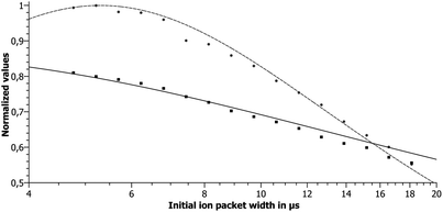 | ||
| Fig. 6 Measured (dots) and calculated (lines) normalized values of the signal-to-noise-ratio (dashed line, circles) and the resolution (solid line, squares). | ||
The measured resolutions and ion mobility of the reactant ion peak for different drift voltages are shown in Fig. 7. The error bars indicate a 95% confidence interval calculated from the t-distribution. Since the observed ion mobility is independent of the applied drift voltage, we do not need to consider any high-field effect in our drift tube.
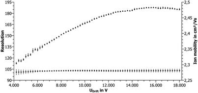 | ||
| Fig. 7 Measured resolution (triangles) and ion mobility (squares). Error bars indicate 95% confidence interval. | ||
Fig. 8 shows the ion mobility spectrum of the reactant ion peak for a drift voltage of 13 kV. The resolution is 182.6 ± 0.5 (95% confidence interval). Thus, compact ion mobility spectrometers can not only compete with large laboratory drift tube IMS, but even surpass their performance. We suggest reporting a confidence interval for the resolution,34 as a single spectrum can reach a much higher apparent resolution due to the noise. For example, a resolution as high as 205 could be reported for our system. As mentioned, this value does not represent the actual resolution.
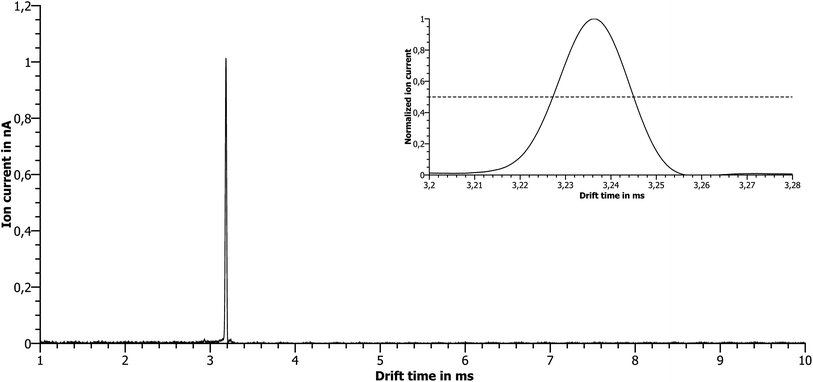 | ||
| Fig. 8 Measured ion mobility spectrum for wInj = 5 μs and UD = 13 kV. The inset shows the measured RIP+ with R = 183. | ||
In order to demonstrate the resolving power, Fig. 9 shows two spectra acquired for a sample gas containing 20 ppbv acetone. Under our operating conditions the protonated acetone monomer's drift time relative to the RIP+ is just 1.007. While the protonated acetone monomer peak is clearly visible in the spectrum with a high resolution of 183, the spectrum with a resolution of 60 does not reveal the presence of a second peak close to the RIP+. The increased resolution therefore provides superior information and hence superior potential for chemical analysis. It should be noted that the same amplifier was used for both spectra shown in Fig. 9.
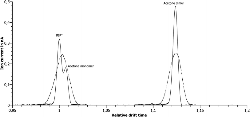 | ||
| Fig. 9 Measured spectra of 20 ppbv acetone at two different resolutions. A resolution of 60 (dotted line) is insufficient to resolve the two peaks visible at a resolution of 183 (solid line). | ||
The limits of detection for acetone have been determined for averaging times of 100 ms (4× averaging) and 1 s (44× averaging). Using three times the standard deviation of the respective noise, the resulting LODs are 580 pptv and 180 pptv.
Conclusions
The viability of both the presented theoretical design approach and the compact high resolution ion mobility spectrometer with a resolution of 183 has been demonstrated. Combining the compact size suitable for portable instruments with limits of detection in the low pptv range and a resolution that surpasses large drift tubes used in lab experiments, this device can be considered as a major breakthrough in performance. Current research includes coupling the presented ion mobility spectrometer to alternative ionization sources to further broaden the measurement possibilities and further resolution enhancement. In addition to that, the option of scaling the presented instrument to the size of a bench top IMS is being evaluated. A drift tube based on the current design with a length of 45 cm would theoretically be able to achieve resolutions in excess of 500. The ability to gather structural information with much simpler instrumentation would make IMS a competitor for low-end, small-scale atmospheric pressure chemical ionization mass spectrometers, and allow their users to perform more analytical tasks.References
- H. Borsdorf and G. A. Eiceman, Appl. Spectrosc. Rev., 2006, 41, 323–375 CrossRef CAS.
- G. A. Eiceman and Z. Karpas, Ion Mobility Spectrometry, CRC Press, 2nd edn, 2004 Search PubMed.
- G. A. Eiceman and J. A. Stone, Anal. Chem., 2004, 76(21), 390A–397A CrossRef CAS.
- H. Borsdorf, T. Mayer, M. Zarejousheghani and G. A. Eiceman, Appl. Spectrosc. Rev., 2011, 46, 472–521 CrossRef.
- A.-E. Kreuder, H. Buchinger, S. Kreuer, Th. Volk, S. Maddula and J. I. Baumbach, Int. J. Ion Mobility Spectrom., 2011, 14(4), 167–175 CrossRef CAS.
- C. J. Bramwell, M. L. Colgrave, C. S. Creaser and R. Dennis, Analyst, 2002, 127, 1467–1470 RSC.
- S. Armenta and M. Blanco, Analyst, 2012, 137, 5891–5897 RSC.
- Z. Karpas, B. Tilman, R. Gdalevsky and A. Lorber, Anal. Chim. Acta, 2002, 463(2), 155–163 CrossRef CAS.
- P. Dwivedi, L. M. Matz, D. A. Atkinson and H. H. Hill, Jr, Analyst, 2004, 129, 139–144 RSC.
- G. A. Harris, S. Graf, R. Knochenmuss and F. M. Fernández, Analyst, 2012, 137, 3039–3044 RSC.
- N. Budimir, D. J. Weston and C. S. Creaser, Analyst, 2007, 132, 34–40 RSC.
- M. Simpson, D. R. Anderson, C. W. McLeod, M. Cooke and R. Saatchi, Analyst, 1993, 118, 1293–1298 RSC.
- K. Cottingham, Anal. Chem., 2003, 75(19), 435A–439A CrossRef CAS.
- D. C. Swanson, Int. J. Ion Mobility Spectrom., 2011, 14(2–3), 125–136 CrossRef.
- E. J. Davis, M. D. Williams, W. F. Siems and H. H. Hill, Jr, Anal. Chem., 2011, 83(4), 1260–1267 CrossRef CAS.
- A. Heptner, P. Cochems, J. Langejuergen, F. Gunzer and S. Zimmermann, Analyst, 2012, 137, 5105–5112 RSC.
- Ph. Dugourd, R. R. Hudgins, D. E. Clemmer and M. F. Jarrold, Rev. Sci. Instrum., 1997, 68(2), 1122–1129 CrossRef CAS.
- C. A. Srebalus, J. Li, W. S. Marshall and D. E. Clemmer, Anal. Chem., 1999, 71(18), 3918–3927 CrossRef CAS.
- S. I. Merenbloom, R. S. Glaskin, Z. B. Henson and D. E. Clemmer, Anal. Chem., 2009, 81(4), 1482–1487 CrossRef CAS.
- R. S. Glaskin, S. J. Valentine and D. E. Clemmer, Anal. Chem., 2010, 82(19), 8266–8271 CrossRef CAS.
- W. Netolicky, P. Holmes, F. Fernandez, J. Tice and B. Musselman, 19th IMSC, Kyoto, 2012 Search PubMed.
- H. Laia, T. R. McJunkin, C. J. Miller, J. R. Scott and J. R. Almirall, Int. J. Mass Spectrom., 2008, 276(1), 1–8 CrossRef.
- J. Langejuergen, P. Cochems and S. Zimmermann, Int. J. Ion Mobility Spectrom., 2012, 15(4), 247–255 CrossRef CAS.
- H. E. Revercomb and E. A. Mason, Anal. Chem., 1975, 47(7), 970–983 CrossRef CAS.
- A. B. Kanu, M. M. Gribb and H. H. Hill, Jr, Anal. Chem., 2008, 80(17), 6610–6619 CrossRef CAS.
- A. Kay, Operational Amplifier Noise: Techniques and Tips for Analyzing and Reducing Noise, Newnes, 2012 Search PubMed.
- E. Oran Brigham, Fast Fourier Transform and Its Applications, Prentice Hall, 1988 Search PubMed.
- M. Tabrizchi, T. Khayamian and N. Taj, Rev. Sci. Instrum., 2000, 71, 2321–2328 CrossRef CAS.
- A. V. Tolmachev, B. H. Clowers, M. E. Belov and R. D. Smith, Anal. Chem., 2009, 81(12), 4778–4787 CrossRef CAS.
- C. A. Hill and C. L. P. Thomas, Analyst, 2003, 128, 55–60 RSC.
- P. Cochems, J. Langejuergen, A. Heptner and S. Zimmermann, Int. J. Ion Mobility Spectrom., 2012, 15(4), 223–229 CrossRef CAS.
- A. A. Shvartsburg, Differential Ion Mobility Spectrometry, CRC Press, 2008 Search PubMed.
- E. V. Krylov and E. G. Nazarov, Int. J. Mass Spectrom., 2009, 285(3), 149–156 CrossRef CAS.
- A. A. Shvartsburg and R. D. Smith, Anal. Chem., 2011, 83(1), 23–29 CrossRef CAS.
| This journal is © The Royal Society of Chemistry 2013 |
