Microfluidic integration of Western blotting is enabled by electrotransfer-assisted sodium dodecyl sulfate dilution
Chenlu
Hou
a and
Amy E.
Herr
*b
aElectrical Engineering & Computer Science, 308B Stanley Hall, University of California, Berkeley, CA, USA. E-mail: hou.chenlu@gmail.com; Tel: +1 510-666-3396
bBioengineering, 308B Stanley Hall, University of California, Berkeley, CA, USA. E-mail: aeh@berkeley.edu; Tel: +1 510-666-3396
First published on 8th October 2012
Abstract
We integrate sodium dodecyl sulfate polyacrylamide gel electrophoresis (SDS-PAGE) with subsequent antibody probing in a single, monolithic microdevice to realize microfluidic Western blotting. A hurdle to successful on-chip Western blotting lies in restoring antibody recognition of previously sized (denatured, reduced) proteins. To surmount this hurdle, we locally dilute free SDS from SDS–protein complexes using differential electromigration of the species during electrotransfer between SDS-PAGE and blotting regions of a microchamber. Local dilution of SDS minimizes re-association of SDS with proteins offering means to restore antibody binding affinity to proteins after SDS-PAGE. To achieve automated, programmable operation in a single instrument, we utilize a 1 × 2 mm2 glass microchamber photopatterned with spatially distinct, contiguous polyacrylamide regions for SDS-PAGE, electrotransfer, and antibody blotting. Optimization of both the SDS-PAGE and electrotransfer conditions yields transfer distances of <1 mm (40 s). The Western blot is completed in 180 s, with fully automated assay operation using programmable voltage control. After SDS-PAGE and electrotransfer, we observe ∼80% capture of protein band mass on the blotting region for a model protein, C-reactive protein. This novel microfluidic Western blot approach introduces fine transport control for in-transit protein handling to form the basis for an automated, rapid alternative to conventional slab-gel Western blotting.
Introduction
Western blotting comprises a suite of bioanalytical techniques critical to measurements spanning from clinical (e.g., confirmatory diagnostics for HIV) to life sciences needs.1–3 Denaturing proteins with sodium dodecyl sulfate (SDS) and performing subsequent polyacrylamide gel electrophoresis (PAGE) to resolve proteins based on size is the gold-standard for molecular weight determination.4 However, protein treatment prior to SDS-PAGE can destroy biological functions.5 SDS removal can restore both enzymatic and immunoaffinity functions suggesting at least partial post-sizing protein renaturation, common for Western blotting.6In conventional Western blotting, SDS removal occurs when sized proteins are transferred from a slab gel to a polymer membrane in the absence of denaturants (such as SDS).7 Transfer includes washing of the blotting membrane for ∼30 min to hours thus limiting throughput. Recent work has adapted macroscale instrumentation (including slab-gel, capillary and array formats) to yield immunoblotting with promising throughput gains.8–11 Automated, fully microfluidic formats for immunoblotting have recently been introduced by our group, with appreciable performance gains over slab-gel systems.12,13 Nevertheless, a crucial challenge to realizing sizing-based Western blotting in passive, microchamber devices has been renaturation of SDS–protein complexes between the sizing and blotting stages. Performance needed for successful integration includes recapitulation of antibody recognition of sized proteins.
To recapitulate antibody recognition of SDS treated proteins, the present study uses rational design of electrotransfer between the protein sizing stage and the antibody blotting stage to demonstrate automated on-chip Western blotting. Electrotransfer of reduced, denatured SDS–protein complexes across a polyacrylamide (PA) gel-filled microchamber – from a PAGE region to a blotting region – allows electrophoresis-assisted SDS dilution and removal from SDS–protein complexes, owing to a differential mobility between free SDS and SDS–protein complexes. Inclusion of this optimized electrotransfer step makes possible antibody recognition of sized proteins in one monolithic microfluidic device. Thus, in lieu of immobilizing SDS–protein complexes to dilute SDS and renature proteins via a washing/incubation step as demonstrated in previous approaches from our group,14,15 we introduce an integrated microfluidic design strategy that separates free SDS from SDS–protein complexes during the electrotransfer process, prior to antibody blotting.
Experimental
Working principle of assay and integration strategy
As illustrated in Fig. 1A and C, the working principle relies on the differential electrophoretic mobility between SDS–protein complexes (SDS–protein) and free SDS molecules (SDS). The mobility difference was hypothesized to allow removal or at a miminum dilution of free SDS from the protein microenvironment, as free SDS has a higher mobility than the SDS–protein complexes being assayed.16,17 Using binding kinetics as a guide, we estimate, to first order, the generation SDS–free protein as: (∂[CRP*])/∂t = −kon[SDS][CRP*] + koff[SDS·CRP*], where CRP* is our model protein, SDS·CRP* is the SDS–decorated protein, and kon and koff are the on and off rates, respectively. Thus, electromigration of free SDS away from the proteins limits the ability of SDS to rebind to proteins by reducing [SDS] associated with the kon term.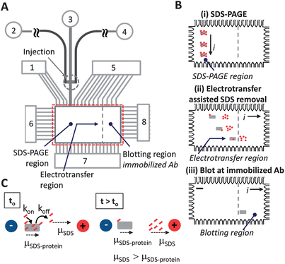 | ||
| Fig. 1 Electrotransfer dilutes SDS from sized proteins underpinning integration of SDS-PAGE with antibody blotting in microfluidic Western blotting. (A) Microchannel and microchamber architecture supports microfluidic Western blotting in regions of photopatterned PA gel for: SDS-PAGE, electrotransfer, and blotting (not to scale). Fluid reservoirs numbered 1–8. Unless specified, denatured protein sample was introduced to reservoir 2; reservoirs 3, 4, and 7 were filled with 1× Tris–glycine buffer with 0.1% (w/v) SDS to maintain protein denaturation during the separation stage; reservoirs 1, 5, 6, and 8 were filled with 1× Tris–glycine native buffer. (B) Integration of sizing with antibody-based blotting in PA gel patterned microchamber is a three step process: (Step i) SDS-PAGE for protein sizing; (Step ii) lateral transfer dilutes SDS from denatured proteins and drives all proteins to the blotting region; (Step iii) proteins bind to partner immobilized antibodies in the blotting region. Electrical current is indicated by “i”, scale bar is 200 microns in schematic. (C) Concept of electrotransfer for dilution of SDS from SDS–protein complexes. Small dashes (red) represent SDS, box symbol (gray) represents protein. Electrophoretic mobility is indicated by “μ” symbols. Electric potential is indicated by “+” and “−“ voltage node symbols. | ||
The Western blotting assay is conducted in a 1 mm × 2 mm microchamber and microfluidic channel network as shown in Fig. 1. Photopatterning created discrete functional zones with SDS-PAGE separation performed along the vertical axis after injection (Fig. 1B, Step i), SDS removal and protein renaturation implemented along the horizontal axis after separation (Fig. 1B, Step ii), and immunoaffinity recognition enabled by the blotting gel (Fig. 1B, Step iii). A non-negligible electrotransfer distance is designed into the Western blotting microdevice to support the electrotransfer-assisted SDS dilution process (Fig. 1B). Through dilution of the local SDS concentration, we seek to produce a sufficient recovery of epitopes recognizable by the immobilized antibodies so that CRP* is available for subsequent recognition by an antibody-decorated blotting membrane.
Western blotting chip fabrication
Glass microfluidic chips were designed in-house with wet etching of glass conducted by the foundry at Caliper Life Sciences (Hopkinton, MA). The fluid access reservoirs were drilled (Cameron Microdrill Press, Sonora, CA) and chips were thermally bonded (Vulcan 3-550, Neytech, York, PA) in-house. To enable covalent attachment of the PA gel to channel walls, microchannels were coated with a self-assembled silane monolayer.18 Bare channels were first incubated with 1 M NaOH for 10 minutes, flushed with house DI water, and then purged by vacuum. A degassed 2![[thin space (1/6-em)]](https://www.rsc.org/images/entities/char_2009.gif) :3:5 (v/v/v) mixture of 3-(trimethoxysilyl)propyl methacrylate, glacial acetic acid, and DI water was then introduced into the channels via capillary flow for silane monolayer formation. Following a 30 min incubation, the channels were rinsed for 10 min with methanol, DI water and purged with vacuum.
:3:5 (v/v/v) mixture of 3-(trimethoxysilyl)propyl methacrylate, glacial acetic acid, and DI water was then introduced into the channels via capillary flow for silane monolayer formation. Following a 30 min incubation, the channels were rinsed for 10 min with methanol, DI water and purged with vacuum.
A 5% linear acrylamide coating was applied to silanized channel walls following previous reports:18 a solution of thoroughly degassed 5% (w/v) acrylamide in 1× Tris–glycine containing 5 mg ml−1 V−1-50 photoinitiator was introduced through the channels by capillary flow, the chip was aligned to a fan-cooled, spectrally filtered mercury lamp (300–380 nm, 100 W, UVP, B100-AP, Upland, CA) 18 cm away (10 mW cm−2 at the plane of the chip measured by a UV513AB Digital Light Meter (General Tools, New York, NY)), and finally exposed for 10 min via flood exposure. Following UV exposure, deionized (DI) water was flushed through the channels by pressure driven flow to displace excess linear acrylamide solution. The linear acrylamide coating was effective in minimizing non-specific adsorption of antibodies onto channel walls during subsequent introduction of blotting gel precursor solution.
Photopatterning and integration of large pore-size loading gel (3%T, 3.3%C), smaller pore-size separation gel (8%T, 3.3%C), and antibody functionalized blotting gel (4.5%T, 3.3%C containing 2 μM biotinylated anti-CRP* antibodies and 5.7 μM streptavidin–acrylamide) within a single device follows techniques presented in recent reports.12,13,19 A Nikon Diaphot 200 (Tokyo, Japan) inverted microscope equipped with a Hamamatsu LightningCure LC5 UV light source and a UV-transmission objective lens (UPLAN-APO 4×, Olympus, Melville, NY) were used for photopatterning of the blotting and separation gel. The intensity output of the UV light source is adjusted to produce an intensity level of 2.2 mW cm−2 measured at the transparent region of a chrome mask (quartz substrate, Photronics, Brookfield, CT) that was placed on the microscope stage. Blotting gel precursor solution was gently introduced to the channels by pressure driven flow. Excess precursor solution was removed from channel reservoirs; drops of high viscosity 5% (w/v) 2-hydroxyethyl cellulose (HEC) were applied to each reservoir and equilibrated for 10 min to yield quiescent flow conditions. Precursor filled chip was aligned on top of the chrome mask exposing the rightmost 700 μm of the 2D chamber. The masked chip was exposed for 4 minutes and unpolymerized blotting gel solution was replaced with separation gel precursor solution by introducing separation gel precursor solution in all reservoirs except reservoir 8 and initiating pressure-driven flow. After application of the HEC solution into each reservoir and an equilibration period of 10 min, the separation gel precursor filled chip was aligned on top of the chrome mask exposing the entire 2D chamber and exposed for 4 minutes. Unpolymerized separation gel solution was replaced with loading gel precursor solution by introducing loading gel precursor solution in reservoirs 1–5 and initiating pressure driven flow. Finally, the unmasked chip was flood exposed for 9 min on a 100 W UV lamp (10 mW cm−2). Overlap in exposed regions during the three subsequent UV polymerizations prevents the formation of any dead volume (i.e., regions where no gel polymerization occurred).
Chip operation and imaging
To conduct the Western blotting assay, a photopatterned chip was secured on an inverted epi-fluorescence microscope (Olympus IX70) equipped with a 10× objective and a Peltier-cooled CCD camera (CoolSNAP HQ2, Roper Scientific, Trenton, NJ). The CCD exposure time was 150 ms and a 4 × 4 binning was employed. A 0.63× demagnifier (Diagnostic Instruments Inc., Sterling Heights, MI) was used to increase the field of view projected onto the CCD to ∼1 mm × 1.3 mm. To image the 2D chamber with a width of 2 mm which was greater than the field of view, a motorized stage allowed separate exposures of the left half and right half of the chamber. The images for the entire chamber were constructed using MacBioPhotontic ImageJ (MacMaster University BioPhotonic Facility). Dual color CCD imaging relied on the use of two filter cubes and independent realizations of separations in each color signal. To produce two-color CCD images, image sequences collected on one spectral channel (AF 488 with Omega Optical GFP filter cube) were summed with image sequences take on the second spectral channel (AF568 with Omega Optical dsRed2 filter cube).A custom in-house high voltage power supply allowed electrophoretic control. Individual platinum electrodes were inserted into the chip reservoirs and used to control protein injection, separation, transfer, and blotting (Table 1). Mapping of the electrodes and reservoirs are provided in Fig. 1A. Unless specified, denatured protein sample was introduced to reservoir 2; reservoirs 3, 4, and 7 were filled with 1× Tris–glycine buffer with 0.1% (w/v) SDS to maintain protein denaturation during the separation stage; reservoirs 1, 5, 6, and 8 were filled with 1× Tris–glycine native buffer. Sample loading (Step 1 in Table 1) is typically conducted for 2 minutes followed by separation (Step 2 in Table 1); voltage programming is switched to transfer and blotting (Step 3 in Table 1) when the fastest migrating peak has reached the bottom of the chamber.
| Applied voltage/current | 1 | 2 | 3 | 4 | 5 | 6 | 7 | 8 |
|---|---|---|---|---|---|---|---|---|
| 1. Sample loading | 0 μA | 0 V | −0.2 μA | 400 V | 0 μA | 0 μA | −0.2 μA | 0 μA |
| 2. Separation | 60 V | 140 V | 0 V | 140 V | 60 V | 0 μA | 160 V | 0 μA |
| 3. Transfer and blotting | 0 μA | 0 μA | 0 μA | 0 μA | 0 μA | 0 V | 0 μA | 75 V |
Proteins and reagents
C-reactive protein (CRP, R&D Systems, Minneapolis, MN) was labeled in-house with Alexa Fluor 488 via manufacturer's instructions (degree-of-labeling: 1–2 dye-mol/CRP-mol) while Parvalbumin (Parv), Ovalbumin (Ova), and Bovine Serum Albumin (BSA) were purchased pre-labeled (Invitrogen, Carslbad, CA). Rabbit polyclonal antibody to human CRP* (Abcam) was biotinylated using a kit (Solulink, San Diego, CA) with a degree of biotinylation of 1.5–3.0 suitable for blotting gel fabrication. Use of the “*” indication refers to the fluorescently labelled analyte. 10× Tris–glycine native electrophoresis buffer (pH 8.3, 25 mM Tris, 192 mM glycine), 10× Tris–glycine–SDS buffer (pH 8.3, 25 mM Tris, 192 mM glycine, 0.1% (w/v) SDS), and SDS were purchased from Bio-Rad Laboratories (Hercules, CA). 2-Mercaptoethanl was purchased from Sigma Aldrich (St. Louis, MO).Solutions of 30% (29:1) acrylamide–bis-acrylamide, 40% acrylamide, 3-(trimethoxysilyl)-propyl methacrylate (98%), glacial acetic acid, 2-hydroxyethyl cellulose, and methanol were purchased from Sigma Aldrich (St. Louis, MO). Photoinitiator 2,2-azobis[2-methyl-N-(2-hydroxyethyl) propionamide] (VA-086) and 2,2′-azobis(2-methylpropionamidine)dihydrochloride (V-50) were purchased from Wako Chemical (Richmond, VA). Streptavidin–acrylamide was purchased from Invitrogen. PA gel precursor solutions of the appropriate acrylamide concentration (T) were prepared by diluting 30% (w/v) acrylamide–bis-acrylamide solution with 1× Tris–glycine native electrophoresis buffer to a total volume containing 0.2% (w/v) VA-086 photoinitiator.
Results and discussion
On-chip SDS-PAGE optimization
To optimize SDS-PAGE, we compared two sizing conditions (Fig. 2): sizing conducted with 0.1% (w/v) SDS in the 1× Tris–glycine separation buffer (SDS injected along the separation axis in the 2D chamber by placing 0.1% (w/v) SDS in wells 3, 4, and 7) and sizing conducted with no SDS in the 1× Tris–glycine separation buffer (SDS not injected along the separation axis). In both cases, proteins were reduced and denatured prior to sizing. Slight horizontal skew of the protein separation axis can be observed owing to asymmetry in the field lines during the separation stage. Sizing with a co-injected stream of SDS (Fig. 2A) yields a linear relationship between protein migration distance (L) and log molecular weight (log MW): L (mm) = −0.47 log MW (Dalton) + 2.62 (R2 = 0.99). At an elapsed separation time of 19 s and a separation distance of 850 μm, all three major peaks in the ladder were resolved (separation resolution, SR > 1.0). In contrast, with no SDS in the separation buffer, a reduction of SR due to broadening of protein peaks was observed (Fig. 2B) even after just 21 s of injection into the SDS free chamber. In the initially SDS-free chamber case, band broadening suggests the presence of multiple protein conformations with different degrees of SDS dissociation, as has been reported in slab-gels and capillaries.17,20,21 No change of migration order was observed due to the short separation time in the microscale system. The on-chip results support the assertion that appreciable SDS dissociation should be attainable in the length and timescales appropriate for on-chip electrotransfer.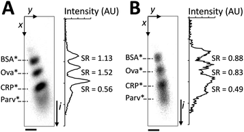 | ||
| Fig. 2 SDS is required in the separation buffer to maintain SDS-PAGE performance. The denatured, reduced protein ladder is co-injected with a run buffer consisting of: (A) 0.1% SDS along the separation axis and (B) no SDS along the separation axis. Panels on the left are inverted epi-fluorescence images, at right are intensity profiles with SR between neighbouring peak pairs indicated. Elapsed separation time of 19 s, E = 66 V cm−1, ladder species are (top to bottom): BSA*, Ova*, CRP*, and Parv* (not resolvable in B). SDS-PAGE was implemented in a chamber containing a 3%T, 3.3%C loading gel in the upper 200 μm and an 8%T, 3.3%C uniform gel in the lower 800 μm. Scale bar indicates 100 μm. | ||
Characterization of differential electromigration for in-transit SDS dilution from SDS–protein complexes
Differential mobility between free SDS and SDS–protein complexes during electrotransfer was studied by considering two PA gel pore-size conditions: a large pore-size (3%T) and a small pore-size (8%T), as shown in Fig. 3. Comparison of the different electrotransfer conditions addresses the question of differential migration and, specifically, the degree to which smaller gel pore sizes enhance mobility differences among analytes for improved SR within a given separation distance.22 As a scalar estimate for electromigration of the non-fluorescing SDS, we visualized electrotransfer of a stream of Alexa Fluor 568 dye dissolved in 0.1% SDS solution. To support this rationale, we note that the critical micellar concentration (cmc) of SDS is 4.3 mM in 1× Tris–glycine buffer23 suggesting that non-bound SDS presented in the transfer process exists primarily as monomers. Comparing electrophoretic mobility measurements of SDS micelles24 to the relative mobility of SDS monomers17 suggests that the electrophoretic mobility of Alexa Fluor 568 dye25 provides a reasonable estimate of the spatial distribution of SDS monomers.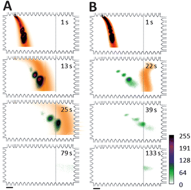 | ||
| Fig. 3 Separation of SDS from proteins during electrotransfer drives reaction toward dissociation. Western blotting images for SDS-surrogate (dye) and fluorescent protein ladder show: (A) large pore-size PA gel transfer region conditions (3%T, 3.3%C) with negligible protein blotting and (B) small pore-size PA gel transfer region conditions (8%T, 3.3%C) with successful protein blotting. Dashed lines indicate the onset of the 4.5%T blotting gel containing 2 μM anti-CRP Ab. Target analyte was CRP*. Two-colour imaging of independent realizations of AF568 and protein ladder injection, separation, and transfer allows visualization of electrotransfer process. ESDS-PAGE = 66 V cm−1, ETransfer = 37 V cm−1, ladder species are (top to bottom): BSA* and CRP* in A; BSA*, Ova*, CRP*, and Parv* in B. Scale bar is 200 μm. | ||
When transfer was performed in a 3%T PA gel (Fig. 3A), the SR between CRP* from Alexa Fluor 568 dye (a scalar surrogate for free SDS monomers) was <0.3 at the blotting region. The capture efficiency for CRP* was ∼20%. In contrast, for the 8% gel electrotransfer conditions (Fig. 3B), the SR between SDS (estimated by Alexa Fluor 568 dye migration) and CRP* exceeded a value of 1.0 after 19 s of electrotransfer. A transfer time of 39 s was sufficient to yield a >80% CRP* capture efficiency on the 4.5%T blotting gel, as measured by comparing retained fluorescence on the blotting region to that in the sized peak prior to entering the blotting gel. Further, the 8%T gel yielded a blotted (captured) CRP* protein bandwidth (transverse) smaller than that observed for the 3%T conditions (∼300 μm width compared to >600 μm width). As demonstrated in our previous work, the transverse width of the captured protein band is dependent upon a competition between an “on” reactive flux (determined by the association rate constant and availability of binding sites here) and a mass transport flux (electromigration).19 Given an identical blotting gel composition and transfer electric field, the increased transverse captured protein bandwidth in the 3% gel implies a smaller association rate constant with the immobilized antibodies or, equivalently, a reduced degree of renaturation. Further optimization of sized protein capture characteristics, including minimization of the immobilized protein bandwidth is currently underway, as smaller blot bandwidths offer higher signal to noise ratios on the blotting gel.
Microfluidic Western blot employing in-transit SDS dilution
For the Western blot assay, we optimized the electrotransfer and blotting buffer conditions required to permit (1) high performance sizing and (2) sufficient SDS dilution/removal for antibody capture of sized proteins in the blotting region. Fig. 4A reports on-chip Western blotting of CRP* in a chamber with 0.1% (w/v) SDS present only along the separation axis and antibodies against CRP* immobilized in the blotting region. Off the separation axis, there is no SDS present in the chamber buffers. Separation and transfer were performed in a 8%T, 3.3%C PA gel and blotting was performed in a 4.5%T PA gel containing 2 μM anti-CRP antibody. For this Western blot, 81% of transferred CRP* was captured by the blotting gel (transfer distance = 0.92 mm; transfer time = 39 s). Capture efficiency was calculated from the total fluorescence signal retained on the blotting gel at t = 129 s divided by the total fluorescence intensity of the CRP* peak upon entering the blotting gel (t = 60 s). Transfer distance was the distance between the CRP* peak center during the separation stage to the edge of the blotting gel. Transfer time was the time elapsed between initiation of the transfer process and the time when the CRP* peak center enters the blotting gel. Ladder proteins (Parv*, Ova*, and BSA*) freely migrated through the blotting gel without immobilization, as expected. Electrotransfer allowed blotting of the sized CRP* peak with a ∼1% shift in peak center position from the SDS-PAGE separation axis to the blotting region. Additionally, minimal disruption of antibody binding capability is expected as SDS only comes in transient contact with antibody immobilized in the blotting gel region.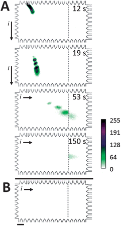 | ||
| Fig. 4 Microfluidic Western blot for CRP*. (A) Western blotting of a ladder, with CRP* as analyte target. Co-injection of 2% SDS treated denatured, reduced proteins in a stream of 0.1% SDS in buffer followed by lateral electrotransfer through an 8% separation gel (no SDS) results in blotting of target analyte by immobilized anti-CRP. Off-target species migrate through blotting gel unimpeded. Ladder species are (top to bottom): BSA*, Ova*, CRP*, and Parv*. (B) Western blotting in a chamber filled with 0.1% SDS in run buffer yields no detectable binding of CRP* (same sample, conditions as A). Elapsed time of 245 s. ESDS-PAGE = 66 V cm−1, ETransfer = 37 V cm−1, SDS-PAGE and transfer were performed in 8%T, 3.3%T gel with blotting performed in 4.5%T PA gel containing 2 μM anti-CRP Ab. Scale bar indicates 200 μm. | ||
In contrast to CRP* with no SDS in the blotting region, Fig. 4B reports the same on-chip Western blot now implemented with the entire chamber filled with 0.1% SDS buffer. In this negative control study, Fig. 4B shows that CRP* failed to bind to the blotting gel after a transfer distance of 1 mm and a corresponding transfer time of 49 s prior to reaching the blotting gel containing anti-CRP antibodies. Due to the uniform SDS concentration present in the chamber, we hypothesize that insufficient dilution of the local SDS concentration hinders recapitulation of antibody binding capability.
By optimizing gel structure (Fig. 3) and buffer condition (Fig. 4) in the electrotransfer region, blotting efficiency achieved after electrotransfer-assisted SDS dilution (>80%) is similar to that obtained using membrane-assisted renaturation approach (∼75%) from our group.15 While both approaches are able to resolve proteins during the separation stage (SR > 1), electrotransfer-assisted SDS dilution eliminates protein deseparation that occurred when transferring proteins to discrete membrane filters.
To estimate the electrotransfer distance needed to recapitulate protein binding to immobilized antibodies, we assayed sized CRP* and varied the distance from the separation axis to the start of the blotting gel (Fig. 5). This distance was varied from 230 μm to 1240 μm. We observed binding of CRP* to the blotting gel region after an electromigration distance of ∼780 μm for all blotting region offsets studied. Taken together these results inform on-chip Western blotting assay and microdevice design, as results support the assertion that a sufficient degree of SDS removal and protein renaturation occurs when electrotransfer of denatured, reduced proteins is conducted in an SDS-free background buffer.
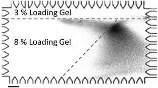 | ||
| Fig. 5 Lateral transfer of a stream of 2% SDS denatured CRP* to a slanted blotting gel. Image captured at t = 200 s after the initiation of the transfer process. The boundary of the slanted blotting gel (as indicated by dashed lines) was visualized by laterally transferring a stream of FITC-biotin into the streptavidin-containing blotting gel. ETransfer = 37 V cm−1, scale bar is 200 μm. | ||
Conclusions
Unified design, a hallmark of microsystems, substantially benefits Western blotting. Dexterity in sample manipulation enabled by voltage programming and the ability to fabricate interconnecting unique functional region with zero dead volume contributes to single-chip integration of multi-assay steps. This advantage is in addition to the expected, but important, advantages afforded through miniaturization, including: reduced manual intervention, nominal sample consumption, rapid electrophoresis results, programmable operation yielding precise control of experimental variables, and digital data collection essential for archiving and comparison. Coupled with automated fluidic manipulation, these factors make microfluidic devices exceptionally well suited formats for multi-step analyses. Consequently, we report microfluidic integration as an assay design strategy for realization of protein Western blotting in an automated, compact instrument.Introduction of electrotransfer between a SDS-PAGE and blotting region of a PA gel photopatterned microfluidic chamber allows in-transit dilution of SDS during transfer of SDS–protein complexes. While optimization of the target blotting conditions to maximize blotted analyte signal are underway, the study summarized here characterizes conditions that yield successful antibody binding to formerly denatured, reduced protein targets. In comparison to macroscale implementation and recent immunoblotting innovation that requires multiple instruments, human intervention, and hours of operation time, our assay was able to sequentially report analyte molecular weight and antibody probing within 3 minutes in a single device under programmable control.
Acknowledgements
The authors acknowledge Drs Mei He and Dohyun Kim as well as Mr Samuel Tia for assistance and helpful discussions. The authors acknowledge financial support from the UC Discovery program and the Industry-University Cooperative Research Program (IUCRP). Partial infrastructure support was provided by the QB3 Biomolecular Nanofabrication Center (BNC). C.H. was a U.S. National Science Foundation Graduate Research Fellow. A.E.H. is an Alfred P. Sloan research fellow in chemistry.Notes and references
- H. Towbin, T. Staehelin and J. Gordon, Proc. Natl. Acad. Sci. U. S. A., 1979, 76, 4350–4354 CrossRef CAS.
- K. Hoebe, X. Du, P. Georgel, E. Janssen, K. Tabeta, S. Kim, J. Goode, P. Lin, N. Mann and S. Mudd, Nature, 2003, 424, 743–748 CrossRef CAS.
- B. M. Branson, JAIDS, J. Acquired Immune Defic. Syndr., 2010, 55, S102 CrossRef.
- K. Weber and M. Osborn, J. Biol. Chem., 1969, 244, 4406–4412 CAS.
- N. S. Choi, J. H. Hahm, P. J. Maeng and S. H. Kim, J. Biochem. Mol. Biol., 2005, 38, 177–181 CrossRef CAS.
- D. A. Hager and R. R. Burgess, Anal. Biochem., 1980, 109, 76–86 CrossRef CAS.
- S. D. Dunn, Anal. Biochem., 1986, 157, 144–153 CrossRef CAS.
- M. F. Ciaccio, J. P. Wagner, C. P. Chuu, D. A. Lauffenburger and R. B. Jones, Nat. Methods, 2010, 7, 148–155 CrossRef CAS.
- G. J. Anderson, C. Cipolla and R. T. Kennedy, Anal. Chem., 2011, 83, 1350–1355 CrossRef CAS.
- W. Pan, W. Chen and X. Jiang, Anal. Chem., 2010, 82, 3974–3976 CrossRef CAS.
- R. A. O'Neill, A. Bhamidipati, X. Bi, D. Deb-Basu, L. Cahill, J. Ferrante, E. Gentalen, M. Glazer, J. Gossett and K. Hacker, Proc. Natl. Acad. Sci. U. S. A., 2006, 103, 16153–16158 CrossRef CAS.
- M. He and A. E. Herr, J. Am. Chem. Soc., 2010, 132, 2512–2513 CrossRef CAS.
- M. He and A. E. Herr, Nat. Protoc., 2010, 5, 1844–1856 CrossRef CAS.
- D. Kim, K. Karns, S. Q. Tia, M. He and A. E. Herr, Anal. Chem., 2012, 84, 2533–2540 CrossRef CAS.
- M. He, J. Novak, B. A. Julian and A. E. Herr, J. Am. Chem. Soc., 2011, 133, 19610–19613 CrossRef CAS.
- K. Kubo, T. Isemura and T. Takagi, J. Biochem., 1975, 78, 349–354 CAS.
- K. Kubo, T. Isemura and T. Takagi, Anal. Biochem., 1979, 92, 243–247 CrossRef CAS.
- A. E. Herr and A. K. Singh, Anal. Chem., 2004, 76, 4727–4733 CrossRef CAS.
- S. Q. Tia, M. He, D. Kim and A. E. Herr, Anal. Chem., 2011, 83, 3581–3588 CrossRef CAS.
- H. Stutz, M. Wallner, H. Malissa, G. Bordin and A. R. Rodriguez, Electrophoresis, 2005, 26, 1089–1105 CrossRef CAS.
- G. F. Schneider, B. F. Shaw, A. Lee, E. Carillho and G. M. Whitesides, J. Am. Chem. Soc., 2008, 130, 17384–17393 CrossRef CAS.
- C. Hou and A. E. Herr, Anal. Chem., 2010, 82, 3343–3351 CrossRef CAS.
- K. L. Gudiksen, I. Gitlin, J. Yang, A. R. Urbach, D. T. Moustakas and G. M. Whitesides, J. Am. Chem. Soc., 2005, 127, 4707–4714 CrossRef CAS.
- J. P. Landers, Handbook of Capillary Electrophoresis, CRC Press, 1997 Search PubMed.
- T. K. Khurana and J. G. Santiago, Anal. Chem., 2008, 80, 6300–6307 CrossRef CAS.
| This journal is © The Royal Society of Chemistry 2013 |