Ionic liquid-assisted microwave reduction of graphite oxide for supercapacitors†
TaeYoung
Kim
a,
Hyun
Chang Kang
b,
Tran
Thanh Tung
c,
Jung
Don Lee
b,
Hyeongkeun
Kim
a,
Woo
Seok Yang
a,
Ho
Gyu Yoon
*b and
Kwang S.
Suh
*b
aElectronic Materials & Device Research Center, Korea Electronics Technology Institute, Seongnam 463-816, Korea
bDepartment of Materials Science and Engineering, Korea University, 5-1 Anam-dong, Seongbuk-gu, Seoul 136-713, Korea. E-mail: hgyoon@korea.ac.kr; suhkwang@korea.ac.kr; Fax: 82 2 929 4408; Tel: 82 2 927 4546
cSmart Plastics Group, European University of Brittany, LIMATB-UBS, Lorient, France
First published on 16th August 2012
Abstract
We present a facile and scalable method for the rapid production of reduced graphene oxide (RG–O) by ionic liquid-assisted microwave chemistry. Microwave irradiation of graphite oxide (GO) in an ionic liquid (IL) enables the rapid reduction of GO within 15 s, producing RG–O containing the IL within their porous structures. The reduced graphene oxide prepared by IL-assisted microwave irradiation (mRG–O) electrodes exhibited a high specific capacitance of ∼135 F g−1, which can be attributed to the open architecture of the mRG–O filled with IL moieties. A supercapacitor made with mRG–O in an IL electrolyte operated at a voltage of 3.5 V and showed a high energy density (∼58 W h kg−1) and power density (∼246 kW kg−1).
Introduction
With an increasing demand for efficient energy storage devices, supercapacitors have become a promising power source for diverse applications, such as portable electronics and electric vehicles.1–5 Since supercapacitors store energy by forming an electrical double layer (EDL) at the electrode/electrolyte interface, the surface area of electrode materials needs to be as high as possible to promote the EDL capacitance.2 The current EDL capacitors that utilize porous activated carbons (ACs) as electrode materials exhibit good stability, but limited EDL capacitance due to the presence of micropores, which are inaccessible to the electrolyte.6–9 In addition, the poor wettability of electrode materials with electrolytes such as ionic liquids has been a limiting factor with regards to the energy density of supercapacitors.10–12 Thus, research has focused on increasing the EDL capacitance and energy density by developing electrode materials with high effective surface areas and good wettability.6–13Graphene, an atomically thin two-dimensional (2D) carbon structure14–16 with a theoretical specific surface area of 2630 m2 g−1 and high electrical conductivity, may be an ideal carbon electrode for EDL supercapacitors as both the surfaces of a graphene sheet are readily accessible to electrolytes.17–20 It has been previously demonstrated that supercapacitors based on chemically modified graphene electrodes exhibit specific capacitance values of 135 and 99 F g−1 in aqueous KOH and organic electrolytes,18 respectively. A variety of graphene-based electrode materials derived from graphite oxide (GO) have been reported to show capacitance values of ∼200 F g−1 in an aqueous electrolyte,18,21 ∼120 F g−1 in organic electrolytes,21,22 and ∼75 F g−1 in an ionic liquid electrolyte.21,23 We have previously demonstrated that reduced graphene oxide (RG–O) exhibits a high capacitance and energy density in an ionic liquid electrolyte when their surfaces are modified with poly(ionic liquids).24
The key challenges associated with the practical use of supercapacitors are finding the cost effective and large-scale production of graphene-based materials, as well as proper control over the effective surface area of the electrodes, which is accessible to electrolyte ions. The most common route towards bulk quantities of graphene-based materials involves the oxidation of graphite to graphite oxide, followed by exfoliation and reduction with chemical reducing agents, such as hydrazine, hydroquinone, sodium borohydride or ascorbic acid.25–28 It has been shown that GO can be reduced by rapid thermal heating under inert gas.22 As a rapid heating source, microwave irradiation has also been used to create exfoliated and reduced GO with loosely stacked platelets.29 The microwave-assisted irradiation provides a facile route to the production of RG–O electrode materials for supercapacitors, but with limited compatibility with high-voltage withstanding electrolytes, such as ionic liquids. More rapid and high yield production methods for RG–O, with an improved compatibility with electrolyte ions, are highly desirable for such applications as electrode materials for energy storage devices. From the perspective of microwave chemistry, ionic liquids (ILs) have received much attention as a new reaction media because they consist entirely of ions with high polarizability and, therefore, absorb microwave radiation efficiently to increase the yields of products with higher reaction rates.30,31 Other practical advantages of ILs include low vapour pressure evolution upon microwave irradiation ensuring safe operation.
By combining the advantages of both ILs and microwave heating, we describe here a facile and scalable route toward the production of RG–O based electrode materials for EDL capacitors. The IL-assisted microwave process leads to the rapid reduction of GO within 15 s. An additional advantage associated with this approach is that the IL, which is used as a reaction medium, is retained in the resulting RG–O structures, allowing for their direct use as electrolytes for supercapacitors. Since ILs are promising solvent-free electrolytes that greatly broaden the electrochemical window during device operation, the approach described herein enables the production of microwave-reduced GO (mRG–O) containing IL electrolytes and thus allows for high voltage supercapacitors with enhanced energy densities.
Experimental
IL-assisted microwave reduction of GO
Graphite oxide (GO) was prepared from natural graphite (Bay Carbon, 200 mesh) via a modified Hummers’ method and dried for 48 h under vacuum. The GO powder was mixed with a predetermined amount of 1-ethyl-3-methyl imidazolium bis(trifluoromethylsulfonyl)imide (EMIM-NTf2, Sigma-Aldrich) as the IL and ground in a mortar. The GO/EMIM-NTf2 was loaded into a glass vial, placed inside a microwave oven, and irradiated at 700 W (2.45 GHz) for a total reaction time of 15 s. The resulting black powder was collected for characterization and preparation of the electrodes.Fabrication of the EDL capacitor from mRG–O
The mRG–O electrodes were prepared as follows: mRG–O powders, conductive carbon black (Super P), and poly(vinylidene fluoride-co-hexafluoropropylene) (PVdF-co-HFP, Kynar 2801) binder dispersed in N-methylpyrrolidinone (NMP) with a weight ratio of 90![[thin space (1/6-em)]](https://www.rsc.org/images/entities/char_2009.gif) :5:5 in an agate mortar. Using a doctor blade, the mixture was coated onto carbon-coated copper foil collectors to form electrodes with a thickness of 42 μm. The electrodes were assembled into a two-electrode 2032-type coin cell configuration by sandwiching the electrodes with a porous polypropylene separator (Celgard 3501). The coin cells were hermetically sealed after the addition of a drop of the electrolyte made from the IL and acetonitrile (EMIM-NTf2/AN, 50/50, w/w).
:5:5 in an agate mortar. Using a doctor blade, the mixture was coated onto carbon-coated copper foil collectors to form electrodes with a thickness of 42 μm. The electrodes were assembled into a two-electrode 2032-type coin cell configuration by sandwiching the electrodes with a porous polypropylene separator (Celgard 3501). The coin cells were hermetically sealed after the addition of a drop of the electrolyte made from the IL and acetonitrile (EMIM-NTf2/AN, 50/50, w/w).
Characterization
A Hitachi S-4800 scanning electron microscope (SEM) was used to image the morphology of the mRG–O samples. X-Ray diffraction (XRD) was recorded for 2θ values from 5° to 30° in a Rigaku model D X-ray diffractometer at 40 keV and 100 mA with a step size of 0.02°. The Fourier transform infrared (FT-IR) spectra of mRG–O were recorded with Bio-Rad Lab FTS-175C. XPS measurements were performed with a VG Microtech, ESCA2000 using monochromatic Al Kα radiation (hν = 1486.6 eV). The thermogravimetric analysis (TGA) was measured with a TA instrument DSC 2010 using a 10° min−1 heating rate under a nitrogen flow (100 ml min−1).Electrochemical measurements were performed with an Eco Chemie Autolab PGSTAT100 potentiastat equipped with the FRA2 frequency response analyzer module. Electrical impedance spectroscopy (EIS) was done with an amplitude of 10 mV over a frequency range of 0.05 Hz to 1 MHz.
Results and discussion
IL-assisted microwave reduction of GO
Fig. 1b shows a photograph of the microwave-reduced graphene oxide (mRG–O) prepared by microwave irradiation of the GO powder with an IL. An IL of EMIM-NTf2 was chosen as it is thermally stable upon microwave radiation and can be directly used as an electrolyte. In a typical experiment, the equivalent weight of EMIM-NTf2 was added to the GO powder and the mixture was treated in a microwave oven at 700 W. Upon microwave irradiation, the yellow GO/EMIM-NTf2 powder (1/1, w/w) and GO suspension in EMIM-NTf2 (0.8 mg ml−1) changed color to black, indicating the rapid reduction of GO (Fig. 1b). It should be noted that intense microwave irradiation of the GO/EMIM-NTf2 mixture for longer than 30 s causes decomposition of the IL and the evolution of a fuming gas. Thus, the total reaction time was set to be less than 30 s, which was sufficient for the reduction of GO. The microwave reduction of GO was completed within 15 s in the presence of the IL, while the reaction time required for the complete reduction of pristine GO powders was over 60 s under the same conditions. These results suggest that the efficient heating of GO by microwave irradiation was achieved in the presence of EMIM-NTf2. Since the ionic liquid, EMIM-NTf2, shows a high dielectric constant and polarizability,32 it is capable of efficiently absorbing microwave energy and converting it into heat, which in turn induces the rapid reduction of GO.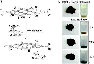 | ||
| Fig. 1 (a) Schematic representation of IL-assisted microwave reduction of GO and (b) photographs of microwave-reduced graphene oxide (mRG–O) prepared by microwave irradiation of GO powder with a small volume of the ionic liquid (left photo, GO/IL = 1/1, w/w) and the GO suspension in the ionic liquid (right photo, GO/IL = 0.8 mg ml−1) | ||
Characterization of microwave-reduced graphene oxide (mRG–O)
A representative SEM image of mRG–O (Fig. 2a) reveals the lightly stacked structure of wrinkled platelets with pores less than 1 μm in size. This 3D-structured morphology of mRG–O may enable the mRG–O to have accessible space for the IL electrolyte.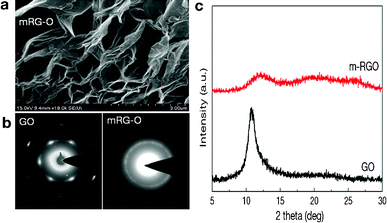 | ||
| Fig. 2 (a) SEM image of mRG–O platelets prepared by 15 s microwave irradiation of GO powder in an IL showing a 3D porous structure, (b) comparison of electron diffraction patterns of GO and mRG–O, (c) XRD patterns of GO and mRG–O. | ||
Fig. 2b compares the SAED patterns of GO and a mRG–O film. While GO shows clear diffraction spots of hexagonal patterns, mRG–O shows a ring pattern rather than a spot pattern indicating that the sample consists of randomly oriented layers. The relative intensities of the inner {100} type and outer {110} reflections indicates that the mRG–O platelets consist of large numbers of monolayers with disordered stacking.20
Fig. 2c compares the XRD pattern of GO and mRG–O. GO shows a XRD peak at 10.6° corresponding to a d-spacing of ∼0.83 nm. In contrast, this XRD peak is absent for mRG–O, except for a broad peak, which is due to mRG–O being largely exfoliated and reduced by microwave radiation.
To investigate the chemical functional groups attached to the graphene sheet, the GO and mRG–O samples were further characterized by FT-IR (Fig. 3a). The spectrum of GO indicates the presence of oxygen functional groups, including carbonyls C![[double bond, length as m-dash]](https://www.rsc.org/images/entities/char_e001.gif) O (1727 cm−1), carboxyls C–O (1414 cm−1), epoxys C–O (1222 cm−1), and alkoxys C–O (1047 cm−1), which is consistent with the previously reported data.33–36 The feature at 1625 cm−1 is assigned to an aromatic CC stretch of the underlying graphitic domains. After microwave treatment, the intensity of the absorption band due to the CO groups (1727 cm−1) decreases significantly. Instead, new absorption bands appear at 1571, 1346, 1170, 1125, 791, 741 and 648 cm−1, which are attributed to the presence of EMIM-NTf2 in the mRG-O sample.37–42
O (1727 cm−1), carboxyls C–O (1414 cm−1), epoxys C–O (1222 cm−1), and alkoxys C–O (1047 cm−1), which is consistent with the previously reported data.33–36 The feature at 1625 cm−1 is assigned to an aromatic CC stretch of the underlying graphitic domains. After microwave treatment, the intensity of the absorption band due to the CO groups (1727 cm−1) decreases significantly. Instead, new absorption bands appear at 1571, 1346, 1170, 1125, 791, 741 and 648 cm−1, which are attributed to the presence of EMIM-NTf2 in the mRG-O sample.37–42
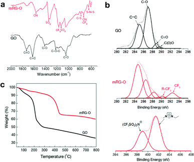 | ||
| Fig. 3 (a) FT-IR spectra of GO and mRG–O. (b) C 1s and N 1s XPS spectra of GO and mRG–O with the peak deconvolution shown. (c) TGA plots of as-prepared GO versus mRG–O. | ||
Fig. 3b compares the XPS spectra of GO and mRG–O. The C 1s core-level spectrum of pristine GO indicates the presence of oxygen-based functional groups on the platelets with deconvoluted peaks at 286.1 (C–OH), 287.6 (CO), and 298 eV (COOH). The C 1s XPS spectrum of mRG–O indicates that these oxygen-based functional groups have been significantly removed by exposure to microwave radiation, which was evidenced by a significantly increased C/O ratio (from <1 to >3).
The TGA curve (Fig. 3c) of the GO sample showed a significant weight loss (∼50% relative to the starting materials) from 30 to 250 °C, mainly due to the evaporation of residual water molecules and the decomposition of the labile oxygen functional groups of GO.25 In contrast, mRG–O has a comparatively small amount of weight loss (∼10%) below 300 °C, indicating substantial removal of the oxygen-containing groups. Instead, mRG–O showed a weight loss from 350 to 450 °C due to the decomposition of EMIM-NTf2 in the mRG–O sample.
Electrochemical performance of mRG–O
On the basis of the above results, we constructed a two-electrode symmetrical supercapacitor cell made from an mRG–O electrode and EMIM-NTf2/AN as an electrolyte, as shown in Fig. 4a. The electrochemical performance of the mRG–O electrodes was analysed by cyclic voltammetry (CV) and galvanostatic charge–discharge.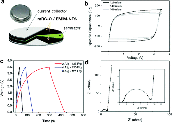 | ||
| Fig. 4 (a) Schematic of the assembled structure of the supercapacitor cell. (b) Cyclic voltammograms of the supercapacitors made with the mRG–O electrodes in EMIM-NTf2. The cycled potential ranges are 0 to 3.5 V with a scan rate of 120, 140 and 160 mV s−1. (c) Galvanostatic charge/discharge curves measured at different current densities. (d) Nyquist plot over the frequency range of 0.05 Hz∼1 MHz. | ||
The CV curves of the mRG–O electrodes were measured with various scan rates in the range of 120–160 mV s−1 for voltage sweeps between 0 and 3.5 V. As shown in Fig. 4b, the mRG–O electrode exhibits nearly rectangular CV traces even at a high scan rate, indicating good capacitive characteristics.17 The non-existence of any spurious peaks in the CV curves suggest that the pseudo-capacitance contribution arising from the presence of the functional groups on the surface of mRG–O is nominal and our device is primarily non-faradic within this voltage window.17,19 The supercapacitor assembled with the mRG–O electrode and IL electrolyte was stable up to 3.5 V, which is attributable to the good electrochemical stability of the IL electrolyte (see ESI†, Fig. S1). We note that the cell operated even at 3.8 V, but with limited cycle life. Hence, we used 3.5 V as a maximum cell voltage for further testing.
The galvanostatic charge/discharge curves for mRG–O (Fig. 4c) show good symmetry and fairly linear slopes with small IR drops, confirming the formation of an efficient electrical double layer and good charge propagation across the two electrodes.17
Assuming a symmetric capacitor, the specific capacitance was calculated by measuring the slope of the galvanostatic discharge curve according to the following equation:43
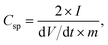
The mRG–O electrodes soaked in the EMIM-NTf2/AN electrolyte exhibited a specific capacitance (Csp) of 135 F g−1 at a current density of 2 A g−1. We note that the control supercapacitor cell with activated carbon (AC) and chemically reduced RG–O electrodes showed specific capacitance values less than 50 F g−1 in the same electrolytes (see ESI†, Fig. S2 and S3), which were significantly lower than for the cell with mRG–O electrodes. The charge storage ability of supercapacitors is directly linked to the wettability of the electrode materials with IL electrolytes. The IL, used as the medium for the microwave reaction, was retained within the mRG–O structures and thus improved the wettability between mRG–O and the IL electrolytes, which partly explains the substantial improvement in the capacitive current.
Fig. 4d shows the impedance curves of mRG–O electrodes as measured over the frequency range of 0.05 Hz–1 MHz. While a depressed semicircle in the high frequency region is modelled by a parallel combination of an interfacial charge transfer resistance and the double layer capacitance, a vertical curve in the low frequency region indicates a nearly ideal capacitive behaviour of the cell.44 By extrapolating the vertical portion of the plot to the real axis gives an equivalent series resistance (ESR) of ∼9 ohms, which is contributed to by both the electrolyte resistance and the electronic resistance of the mRG–O electrodes. A straight line with a slope of 45° in the low frequency range is represented by Warburg impedance, resulting from the frequency dependence of ion diffusion and transport in the electrolyte.44 The mRG–O electrode shows a short Warburg region, indicating the enhanced access of electrolyte ions in the porous structure of the electrodes.
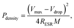
To evaluate further the performance of the supercapacitors based on the mRG–O electrodes, the energy density (E) and power density (P) were calculated from the galvanostatic charge/discharge curves, considering the total mass (M) of active materials from both electrodes.40 The total resistance based on the internal resistance (IR) drop from the charge–discharge curves was used to calculate P and E for the assembled device, of which the value (∼8.6 Ω) was close to the value (∼9 Ω) obtained from the EIS measurement.
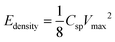
where M is the total mass of mRG–O on two electrodes and RESR is the equivalent series resistance determined from the voltage drop at the beginning of the discharge at a certain constant current. The overall performance of our mRG–O supercapacitors is summarized in the Ragone plot describing the relationship between E and P. Using the specific capacitance value of 135 F g−1 and operation voltage of 3.5 V, a maximum energy density of ∼58 W h kg−1 was achieved along with the highest power density of ∼246 kW kg−1 (Fig. 5a). In the case where the plot were normalized to the total mass of two electrodes including all the components, such as the electrodes, electrolyte, and current collectors, the energy density and power density were calculated to be 5.7 W h kg−1 and 12 kW kg−1, respectively. Compared to similar systems reported previously using graphene-based electrodes and IL electrolytes,20,22 our supercapacitor exhibits a comparable energy density and power density. As discussed earlier, the energy density of a supercapacitor is governed by the overall capacitance and the operating voltage. The use of an IL electrolyte increases the operating voltage compared to aqueous and organic electrolytes, thus enhancing the energy densities. The cycling test of the cells shows ∼97% capacitance retention over 1000 cycles at a current density of 2 A g−1, demonstrating an excellent cycling performance achieved with our supercapacitor. (Fig. 5b)
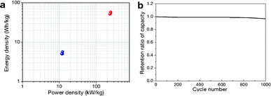 | ||
| Fig. 5 (a) Ragone plot of energy density versus power density. The energy density and power density were normalized to the mass of mRG–O from both electrodes (blue dots) and the total mass of the two electrodes, including the active materials, electrolyte, and current collectors. (b) Cycling performance of our supercapacitor, showing a capacitance retention of ∼97% after 1000 cycles of charging and discharging at a current density of 2 A g−1. | ||
Conclusion
In summary, we have developed a facile and scalable method to rapidly produce reduced graphene oxide by ionic liquid-assisted microwave chemistry. The efficient microwave dielectric heating afforded by the ionic liquid led to the rapid reduction of graphite oxide, producing a reduced graphene oxide with ionic liquid retained within their structure. We believe that such a facile and scalable process for graphene electrode/electrolyte systems can offer great promise in energy storage device applications.Acknowledgements
This work was supported by SOLOE Tech. Co. Ltd. (Korea)References
- B. E. Conway, Electrochemical Supercapacitors: Scientific Fundamentals and Technological Applications, Kluwer Academics and Plenum, New York, 1999 Search PubMed.
- P. Simon and Y. Gogotsi, Nat. Mater., 2008, 7, 845 CrossRef CAS.
- J. R. Miller and P. Simon, Science, 2008, 321, 651 CrossRef CAS.
- J. Chiola, G. Yushin, Y. Gogotsi, C. Portet, P. Simon and P. L. Taberna, Science, 2006, 324, 1312 Search PubMed.
- J. B. Goodenough, Report of the Baic Energy Sciences Workshop for Electrical Energy Storage, Department of Energy, 2007 Search PubMed.
- K. Jurewicz, K. Babel, A. Ziokowski and H. Wachowska, Electrochim. Acta, 2003, 48, 1491 CrossRef CAS.
- G. Lota, B. Grzyb, H. Machnikowska, J. Machnikowski and E. Frackowiak, Chem. Phys. Lett., 2005, 404, 53 CrossRef CAS.
- D. Hulicova, J. Yamashita, Y. Soneda, H. Hatori and M. Kodama, Chem. Mater., 2005, 17, 1241 CrossRef CAS.
- K. Yang, S. Yiacoumi and C. Tsouris, J. Electroanal. Chem., 2003, 540, 159 CrossRef CAS.
- E. Frackowiak and F. Beguin, Carbon, 2001, 39, 937 CrossRef CAS.
- B. Fang and L. Binder, J. Power Sources, 2006, 163, 616 CrossRef CAS.
- M. Galinski, A. Lewandowski and I. Stepniak, Electrochim. Acta, 2006, 51, 5567 CrossRef CAS.
- S. Murali, D. R. Dreyer, P. Valle-Vigon, M. D. Stoller, Y. Zhu, C. Morales, A. B. Fuertes, C. W. Bielawski and R. S. Ruoff, Phys. Chem. Chem. Phys., 2011, 13, 2652 RSC.
- A. K. Geim and K. S. Novoselov, Nat. Mater., 2007, 6, 183 CrossRef CAS.
- K. S. Novoselov, A. K. Geim, S. V. Morozov, D. Jiang, Y. Zhang, S. V. Dubonos, I. V. Grigorieva and A. A. Firsov, Science, 2004, 306, 666 CrossRef CAS.
- M. I. Katsnelson, Mater. Today, 2007, 10, 20 CrossRef CAS.
- M. D. Stoller, S. Park, Y. Zhu, J. An and R. S. Ruoff, Nano Lett., 2008, 8, 3498 CrossRef CAS.
- D. R. Dreyer, S. Park, C. W. Bielawski and R. S. Ruoff, Chem. Soc. Rev., 2010, 39, 228 RSC.
- Y. Wang, Z. Shi, Y. Huang, Y. Ma, C. Wang, M. Chen and Y. Chen, J. Phys. Chem. C, 2009, 113, 13103 CAS.
- S. Stankovich, D. A. Dikin, G. H. B. Dommett, K. M. Kohlhaas, E. J. Zimney, E. A. Stach, R. D. Piner, S. T. Nguyen and R. S. Ruoff, Nature, 2006, 442, 282 CrossRef CAS.
- W. Lv, D. Tang, Y. He, C. You, Z. Shi, X. Chen, C. Chen, P. Hou, C. Liu and Q. Yang, ACS Nano, 2009, 3, 3730 CrossRef CAS.
- Y. Zhu, M. D. Stoller, W. Cai, A. Velamakanni, R. D. Piner, D. Chen and R. S. Ruoff, ACS Nano, 2010, 4, 1227 CrossRef CAS.
- S. R. C. Vivekchand, C. S. Rout, K. S. Subrahmanyam, A. Govindaraj and C. N. R. Rao, J. Chem. Sci., 2008, 120, 9 CrossRef CAS.
- T. Y. Kim, H. W. Lee, M. D. Stoller, D. R. Dreyer, C. W. Bielawski, R. S. Ruoff and K. S. Suh, ACS Nano, 2011, 5, 436 CrossRef CAS.
- H. Shin, K. K. Kim, A. Benayad, S. Yoon, H. K. Park, I. Jung, M. H. Jin, H. Jeong, J. M. Kim, J. Choi and Y. H. Lee, Adv. Funct. Mater., 2009, 19, 1987 CrossRef CAS.
- S. Stankovich, D. A. Dikin, R. D. Piner, K. A. Kohlhaas, A. Kleinhammes, Y. Jia, Y. Wu, S. T. Nguyen and R. S. Ruoff, Carbon, 2007, 45, 1558 CrossRef CAS.
- J. Zhang, H. Yang, G. Shen, P. Cheng, J. Zhang and S. Guo, Chem. Commun., 2010, 46, 1112 RSC.
- D. R. Dreyer, S. Murali, Y. Zhu, R. S. Ruoff and C. W. Bielawski, J. Mater. Chem., 2011, 21, 3443 RSC.
- Y. Zhu, S. Murali, M. D. Stoller, A. Velamakanni, R. D. Piner and R. S. Ruoff, Carbon, 2010, 48, 2106 CrossRef.
- T. Yan, C. J. Burnham, M. G. D. Popolo and A. Voth Gregory, J. Phys. Chem. B, 2004, 108, 11877 CrossRef CAS.
- O. Borodin, J. Phys. Chem. B, 2009, 113, 11463 CrossRef CAS.
- Y. Xia, J. H. Cho, J. Lee, P. P. Ruden and C. D. Frisbie, Adv. Mater., 2009, 21, 2174 CrossRef CAS.
- C. Hontoria-Lucas, A. J. Lopez-Peinado, J. D. D. Lopez-Gonzalez, M. L. Rojas-Cervantes and R. M. Martin-Aranda, Carbon, 1995, 33, 1585 CrossRef CAS.
- G. I. Titelman, V. Gelman, S. Bron, R. L. Khalfin, Y. Cohen and H. Bianco-Peled, Carbon, 2005, 43, 641 CrossRef CAS.
- N. B. Colthup, L. H. Daly, S. E. Wiberley, Introduction to Infrared and Raman Spectroscopy, Academic Press, London, 1990 Search PubMed.
- S. Stankovich, R. D. Piner, S. T. Nguyen and R. S. Ruoff, Carbon, 2006, 44, 3342 CrossRef CAS.
- N. E. Heimer, R. E. Del Sesto, Z. Meng, J. S. Wilkes and W. Robert Carper, J. Mol. Liq., 2006, 124, 84 CrossRef CAS.
- J. Kiefer, J. Fries and A. Leipertz, Appl. Spectrosc., 2007, 61, 1306 CrossRef CAS.
- D. Lin-Vein, N. B. Colthup, W. G. Fateley, J. G. Grasselli, The Handbook of Infrared and Raman Charateristic Frequencies of Organic Molecules, Academic Press, Boston, 1991 Search PubMed.
- I. Rey, P. Johansson, J. Lindgren, J. C. Lasse`gues, J. Grondin and L. Servant, J. Phys. Chem. A, 1998, 102, 3249 CrossRef CAS.
- V. Di Noto, M. Vittadello, S. G. Greenbaum, S. Suarez, K. Kano and T. Furukawa, J. Phys. Chem. B, 2004, 108, 18832 CrossRef CAS.
- K. Nakamoto, Infrared and Raman Spectra of Inorganic and Coordination Compounds, John Wiley and Sons, New York, 1986 Search PubMed.
- Y. Zhu, S. Murali, M. D. Stoller, K. J. Ganesh, W. Cai, P. J. Ferreira, A. Pirkle, R. M. Wallace, K. A. Cychosz, M. Thommes, D. Su, E. A. Stach and R. S. Ruoff, Science, 2011, 332, 1537 CrossRef CAS.
- J. E. B. Randles, Discuss. Faraday Soc., 1947, 1, 11 RSC.
Footnote |
| † Electronic Supplementary Information (ESI) available: additional data for the supercapacitors with various electrode materials, including activated carbon, chemically-reduced graphite oxide and microwave-reduced graphite oxide. See DOI: 10.1039/c2ra21400h/ |
| This journal is © The Royal Society of Chemistry 2012 |