Theoretical model of substrate-assisted self-assembly of DNA nanostructures†
Shogo
Hamada
* and
Satoshi
Murata
*
Department of Bioengineering and Robotics, Graduate School of Engineering, Tohoku University, Sendai, Miyagi 980-8579, Japan. E-mail: hamada@molbot.mech.tohoku.ac.jp; shogo@nanoeng.net (S.H.); murata@molbot.mech.tohoku.ac.jp (S.M.); Tel: +81 (0)22-795-6910 (S.H.) Tel: +81 (0)22-795-4100 (S.M.)
First published on 29th May 2012
Abstract
Substrate-assisted self-assembly [S. Hamada and S. Murata, Angew. Chem., Int. Ed., 2009, 48, 6820; X. Sun et al., J. Am. Chem. Soc., 2009, 131, 13![[thin space (1/6-em)]](https://www.rsc.org/images/entities/char_2009.gif) 248] is a novel methodology for DNA self-assembly to fabricate large-scale DNA nanostructures on substrate surfaces. Although a qualitative explanation of this phenomenon and some experimental results exist, the mechanism is not yet thoroughly understood. A theoretical framework will improve understanding and enable us to exploit this phenomenon for further development and future applications. Here, we propose a model and simulations describing this phenomenon, with comparison to experimental results. The model is based on simple thermodynamics and was converted into quasi-static kinetics to trace the overall process of adsorption and self-assembly during annealing. As an example, a simulation of T-motif Ring formation based on this model successfully reproduced the difference between yields in solution and on a surface, consistent with experimental observations.
248] is a novel methodology for DNA self-assembly to fabricate large-scale DNA nanostructures on substrate surfaces. Although a qualitative explanation of this phenomenon and some experimental results exist, the mechanism is not yet thoroughly understood. A theoretical framework will improve understanding and enable us to exploit this phenomenon for further development and future applications. Here, we propose a model and simulations describing this phenomenon, with comparison to experimental results. The model is based on simple thermodynamics and was converted into quasi-static kinetics to trace the overall process of adsorption and self-assembly during annealing. As an example, a simulation of T-motif Ring formation based on this model successfully reproduced the difference between yields in solution and on a surface, consistent with experimental observations.
1 Introduction
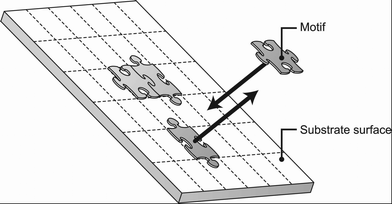
Substrate-assisted self-assembly,1 also known as surface-mediated self-assembly,2 is a novel, versatile methodology for DNA self-assembly, which enables creation of large-scale two-dimensional nanostructures covering an entire substrate surface. Potentially, this method combines a top-down fabrication process using substrates and a bottom-up fabrication using structural DNA nanotechnology. The fabrication process of substrate-assisted self-assembly is straightforward: DNA motifs are simply annealed with a substrate fragment. A qualitative explanation for this phenomenon is that the negatively charged DNA motifs are adsorbed onto the negatively charged substrate via counter-ion binding and, because of this two-dimensional constraint of motifs on the surface, self-assembly on the substrate surface is enhanced. Experimental results successfully demonstrated this concept using mica and silica surfaces.3 Moreover, DNA motifs used for this self-assembly technique are not restricted to limited, specific motifs but can be applied to a variety of motifs with a wide range of geometries. For example, three-point star, DX, SST and T-motifs and even protein attachments on those arrays4 have already been realized. However, the mechanism of substrate-assisted self-assembly has not been well-understood, because of a lack of systematic research on the binding of DNA nanostructures to the substrate surface. To use this methodology for large-scale fabrication with precision in future applications, we must understand the overall phenomena that are occurring on the surface and in solution. The space-time history of species and the states of DNA nanostructures on surfaces are currently difficult to follow in real time because of the constraints in atomic force microscopy (AFM) observations, such as long-term observations during annealing and physical interference by AFM probes. Details of the mechanism and quantitative information on each state are required to enable the design of substrate-assisted self-assembly under arbitrary conditions. In this paper, first we propose a theoretical framework for substrate-assisted self-assembly. Then, based on the simplified reaction pathways, we construct a thermodynamic model of substrate-assisted self-assembly, using Derjaguin and Landau, Verwey and Overbeek (DLVO) theory to calculate adsorption energy and the nearest-neighbor method for DNA hybridization to calculate self-assembly. Finally, we convert this thermodynamic model into a quasi-static kinetic model to follow the space–time history of substrate-assisted self-assembly by computer simulation.2 Framework of the model
The framework for this model was inspired by several previous studies about adsorption and 2D-diffusion-based interactions of molecules with a surface. The enhancement of reaction rate for receptor–ligand interactions on a cell surface is suggested to result from a “reduction of dimensionality” effect.5 This phenomenon occurs because of the effect of non-specific adsorption of the ligand on the surface and is modeled as a combined reaction–diffusion limited model.6 The model has been modified and extended to represent heterogeneous DNA–DNA hybridization on a solid surface, on the basis that hybridization with the immobilized DNA strand can occur either directly via 3-dimensional diffusion or by nonspecific reversible adsorption followed by 2-dimensional diffusion on the surface.7,8 Although adsorption models consider an irreversible process of molecules attaching to receptors or probes on the surface, they clearly specify two general pathways for interaction with the surface; one is by 3D diffusion with an irreversible direct attachment process, and the other is by 2D diffusion and irreversible attachment, along with adsorption to the surface. These models suggest that a similar model can be applied to substrate-assisted self-assembly, in which the mechanism is simplified into combinations of the self-assembly process with hybridization, and adsorption–desorption processes with surface–molecule interactions. We partially adopted and modified these models to represent the overall phenomenon of substrate-assisted self-assembly. Namely we adopted the idea of an adsorption and 2D diffusion process because DNA motifs must be present on the surface before they can self-assemble (i.e. it is assumed that the adsorption process occurs first and then the motifs occupy a certain area on the substrate). On the other hand, we constructed a model with a reversible process for all reactions, including self-assembly, because reversible reaction rates based on kinetics affect the behavior of each species during substrate-assisted self-assembly.Based on the above considerations, we developed a model for the mechanism of substrate-assisted self-assembly (Fig. 1). Self-assembly may occur in both free-solution and on the substrate surface. Multiple pathways can be conceived for such a process; two types, such as n-mer + monomer and partial n+m-mer reactions are included in our model and simulations. Adsorption–desorption processes of all species also take place. (Although this scheme seems rather complex, note that the reaction is only based on combinations of two elements, such as adsorption–desorption and self-assembly.)
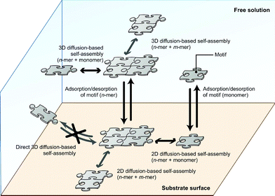 | ||
| Fig. 1 Schematic of the substrate-assisted self-assembly. | ||
3 Calculation of free energy change
To build a quantitative model, we must first calculate the Gibbs free energy difference for each reaction to derive the thermodynamic equilibrium between each state. Because we simplified the mechanism into two types of reaction, for example self-assembly and adsorption, we can consider them independently.3.1 Self-assembly
The process of self-assembly can be considered as the hybridization between sticky ends of motifs. The nearest-neighbor method is applied to our model because it predicts hybridization reactions well and also is a widely-used method for simulations and calculation of self-assembly in DNA nanotechnology. Parameters taken from ref. 9 were used for the calculation. Note that these parameters are for the hybridization of two single strands: hybridizations under restricted freedom, such as self-assemblies on a surface and open–close state transition of the ring structure, which we describe in the simulation, would be different. However, to simplify the calculation, our simulation uses the same parameters for all reactions.3.2 Adsorption–desorption
The free energy change for adsorption–desorption can be calculated from the interaction energy curve between the surface and DNA in monovalent and divalent cation solutions. Although there have been other theoretical and experimental studies of the interaction between DNA and a mica surface mediated by monovalent and multivalent cations using the counterion correlation model,10,11 in this section, Sushko et al.’s model12,13 is used to calculate the energy curve between DNA and the mica surface because of the simple form of the calculations and readily obtainable parameters. The Sushko model is based on Derjaguin and Landau, Verwey and Overbeek (DLVO) theory; it calculates the sum of van der Waals (vdW(d)) and double-layer (Edl(d)) energies between the DNA helix (considered as a cylinder) and the mica surface (considered as a plane with infinite size) as a function of distance d.| DLVO(d) = vdW(d) + Edl(d) | (1) |
Our calculations for the DLVO energy curve are based on Sushko’s source codes14 (details are given in ESI 1,2†).
The resultant DLVO energy curve (Fig. 2) has one shallow minimum at 3.5 [nm], −0.02 [eV/bp]. We use this value as a constant adsorption energy for DNA on mica (per bp) in the following thermodynamics and quasi-static kinetics.
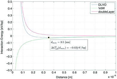 | ||
| Fig. 2 DLVO energy calculation between DNA and a mica surface in TAE/Mg2+ 12.5 mM buffer, 300 K. The green line indicates the van der Waals energy curve. The red line indicates the double-layer energy curve, and the blue line is the DLVO energy curve, calculated as the sum of both energies. | ||
4 Thermodynamics of substrate-assisted self-assembly
4.1 Self-assembly
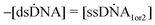
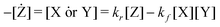
The process of substrate-assisted self-assembly is modeled by a reaction between motifs. The hybridization reaction is modeled as a two-state, first-order system,15,16| ssDNA1 + ssDNA2 ⇄ dsDNA | (2) |
Hereafter, the identification of each species is simplified as follows,
| X + Y ⇄ Z | (3) |
In the case of motif-based self-assembly, we regard X, Y and Z as the species of each structure (motif or motifs).
 | (4) |
We assumed that the activity coefficient is the same for all species (γk = γ(const.)), because the size of the molecule and number of reaction sites are supposed to be the main determining factor for this coefficient. In the case of DNA motifs, we can approximate the size of molecules and the number of reaction sites (i.e. sticky ends) as essentially similar.
 | (5) |
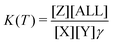
The thermodynamic equilibrium constant can be expressed as a function of the Gibbs free energy of reaction (ΔG0rxn) via the definition of chemical potential μ0k(T),
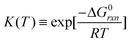 | (6) |
Eqn (5) and (6) can be rewritten by an expression using Kc(T) (equilibrium of concentration),‡
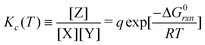 | (7) |
![[triple bond, length as m-dash]](https://www.rsc.org/images/entities/char_e002.gif) γ/[ALL] is defined as an activity parameter.
γ/[ALL] is defined as an activity parameter.
Note that q is approximated as a constant in this model, because the total number of molecules can be considered to be almost constant (at least in magnitude) in our simulation.
Using the same derivation method, the relation between the equilibrium constant using concentrations and the Gibbs free energy of the reaction X ⇄ Z can be defined and written as,
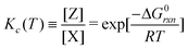 | (8) |
Note that the parameter q does not appear in this case.
4.2 Adsorption
The adsorption model for substrate-assisted self-assembly is considered as a Langmuir model. The reason for using this model is that various experimental results for non-specific adsorption of DNA on glass surfaces and many other cases of polymer adsorptions are well-explained by this model.7 Glass surfaces are negatively charged,17 similar to the mica surface, so the mechanism of the adsorption–desorption itself can be presumed to be identical. Moreover, experimental results for T-motifs grown on a mica surface suggest that the surface is always covered by a monolayer of DNA nanostructures, indicating that a multi-layer adsorption model such as the Brunauer, Emmett and Teller (BET) model,18 is likely to be inappropriate for this mechanism.The Langmuir model can be defined as a “reaction” of adsorption, in which S* is the empty adsorption site, P is the molecule and SP is the adsorption site occupied by the molecule.
| S* + P ⇄ SP | (9) |
The equation suggests that the concentration equilibrium by the Langmuir model and relationship with free energy can be written as,
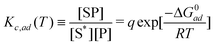 | (10) |
Note that the activity coefficient γad is the same in this case. γad = γ is used in simulations, because if we assume γad of [SP] and [S*] are the same (both are related with adsorption sites), those two factors are reduced; therefore the residual γad is related to [P].
5 Quasi-static kinetics of substrate-assisted self-assembly
5.1 Self-assembly
This section describes a kinetic model for the self-assembly and adsorption in a quasi-static process.The velocities of the reaction (2) are defined as,
 | (11) |
| = kr[dsDNA] − kf[ssDNA1][ssDNA2] | (12) |
Using simplified expressions for the motifs,
| X + Y ⇄ Z | (13) |
 | (13) |
| X ⇄ Z | (15) |
 | (14) |
The velocities are 0 at equilibrium, thus, Kc(T) = kf/kr is applicable in our quasi-static model.
The forward reaction can be considered as a diffusion-based reaction but the rate-limiting step both in free solution and on a surface, is approximately independent of oligo length and sequence.19 Experimental results support this speculation;7 the rate constant for oligonucleotide association in solution is about 4 × 10⁶ [M−1 s−1], which is two to three orders of magnitude smaller than the diffusion-limited rate.20 Another fluorescence resonant energy transfer (FRET) experiment gave a rate constant of 5.7 × 10⁵ [M−1 s−1], despite the estimated diffusion-limited rate being 8.9 × 10⁹ [M−1 s−1].21 In this paper, the rate defined by Winfree16 for the theory of self-assembly of DNA tiles (kf ≈ 6 × 10⁵ [M−1 s−1]) is used.§
Thus, using this notation, the reverse reaction rate is defined as
| X + Y ⇄ Z | (17) |
 | (15) |
| X ⇄ Z | (19) |
 | (16) |
Note that these thermodynamic and kinetic expressions for the reaction disregard the effect of activation energy.
5.2 Langmuir model for adsorption
The Langmuir adsorption model uses the concept of “adsorption sites”, which are considered as exclusive binding sites for the molecule. In the case of substrate-assisted self-assembly on a substrate surface, this concept can be interpreted as a hypothetical “lattice” for the substrate surface; each area represents one exclusive binding site for one motif (Fig. 3). (Each [mn] occupies n sites.) A motif (or motifs) can move on the surface, so the number of empty binding sites can be regarded as an unoccupied area on the surface divided by the area of one site (which is equivalent to the area of a single motif). Thus, the total number of adsorption sites can be calculated as | (17) |
 | ||
| Fig. 3 Lattice model of a substrate surface. | ||
Using thermodynamic adsorption equilibrium (eqn (10)), the adsorption rates represented in terms of [mol l−1] can be defined as
 | (18) |
 | (19) |
Also, the desorption rate constant (kde) can be defined using eqn (10)
 | (20) |
The theoretical forward adsorption rate constant kad can be calculated by using the method of Chan et al.7 However, the actual adsorption rate is considered to be highly dependent on the conditions; the theoretical calculation generally defines only an upper limit of the constant. It suggests that the forward reaction is three-dimensional diffusion-based (ESI 4†); therefore, in the simulation below, we use the same value introduced in self-assembly as a realistic value for the forward adsorption rate constant.
6 Simulation
6.1 Model
The kinetic model of substrate-assisted self-assembly was applied to the computer simulation. The aim of this simulation was to demonstrate that unique phenomena related to substrate-assisted self-assembly can be explained through this theory. The T-motif 1.0x ring (Fig. 4a) was chosen for the simulation model for the following reasons: 1. It has a closed structure with a simple and size-controllable22 design; 2. It has a simple formation mechanism without a nucleation process; 3. Bulk reaction tracing is possible by spectrophotometer in free solution experiments; 4. The increase in formation yield, which is one of the important effects of substrate-assisted self-assembly, was clearly observed by previous experiments.1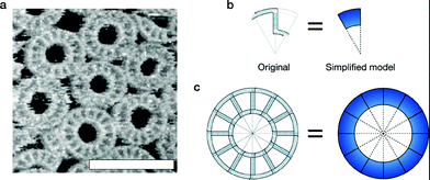 | ||
| Fig. 4 T-motif ring structure. a AFM observation of T-motif ring 1.0x structures on mica surface (free-solution self-assembly). Scale bar = 100 nm. See ESI 7† for the experimental details. b Original motif design of ring 1.0x and simplified representation (simulation model). c Original design of the final ring structure and simplified representation. | ||
A simplified motif model was used in our simulations (Fig. 4b). Although some distributions are observed in the diameter of the closed structure because of the flexibility in “real” motifs, we assumed that the model is always rigid, forming a closed “dodecagon” structure, as designed (Fig. 4c). The motif behaves as a molecule, or species in the reaction.
6.2 Simulation in free-solution
Simulation of self-assembly in free-solution is modeled as follows (Fig. 5):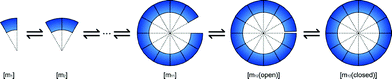 | ||
| Fig. 5 Simulation model of self-assembly in free solution. | ||
[mn] consists of n × [m1] motifs. The connections between motifs are made by hybridization of the two single-stranded regions (one is a sticky end, and the other is a single-stranded bulge section) of the motif. Two connecting regions are considered to be hybridized at the same time. [m12] has two states, “open” and “closed”; the difference between those states involves the hybridization of the last two sticky ends.
To simplify the reaction, we consider only two types of pathways for self-assembly, i.e.:
| [mn] + [m1] ⇄ [mn+1] | (21) |
| [mn] + [m12−n] ⇄ [m12(open)] | (22) |
The same equations and parameters described in the theory section were used. Although the pathways are limited, the reaction mainly relies on [m1], so the qualitative behavior of this model is conserved.
First, the simulation was compared to the formation curve experiments using UV (260 nm) absorbance observation by spectrophotometer. The initial adjustment was done by comparing the Tf of 0.66 μM, −0.3 °C min−1 (ESI 5.1.1, 6.1†). The experimental results showed Tf = 312.48 [K]. The parameter q was obtained as 1/q = 6 × 10⁴ from the result (ESI 5.1.2†). The Tf calculated from the simulation was 311.6 [K]. Note that a larger 1/q gives a lower Tf.
To verify the accuracy of q and the model, a comparison of additional results at different temperature and annealing rates was made (ESI 5.2†). The experimental results were in excellent agreement with the simulation results for Tf, at least between orders of 10−1∼101 μM.
6.3 Simulation of substrate-assisted self-assembly
Next, the simulation of substrate-assisted self-assembly was conducted with the extended model of the previous section along with the obtained parameter q. Here, species on the surface and the adsorption-desorption reactions were added (Fig. 6).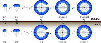 | ||
| Fig. 6 Simulation model of substrate-assisted self-assembly. | ||
Again, the self-assembly pathways used in this simulation were the same as those used in free-solution (eqn 21,22).
For accurate experimental conditions, the volume of reaction chamber was set to 200 [μl], the area of the substrate surface (mica) was set to 5 × 7 (×2)[mm2], and the initial concentration [m1(sol)] was set to 0.1 [μM]. The annealing rate was −0.05 °C min−1.
The simulation results (0.1 μM, 1/q = 6 × 10⁴) revealed some characteristics of substrate-assisted self-assembly. Time developments of the species (Fig. 7, ESI 6.2†) shows the effect of substrate adsorption. The difference between the rate constants in 3D and 2D gives different proportions of each species in solution and on the surface.
![Concentrations of the species on the substrate surface using substrate-assisted self-assembly. At high temperature, the monomer [m1] dominates on the substrate surface. During annealing, intermediate molecules ([m2]∼[m12(open)]) are formed and finally [m12(close)] dominate on the surface.](/image/article/2012/RA/c2ra20764h/c2ra20764h-f7.gif) | ||
| Fig. 7 Concentrations of the species on the substrate surface using substrate-assisted self-assembly. At high temperature, the monomer [m1] dominates on the substrate surface. During annealing, intermediate molecules ([m2]∼[m12(open)]) are formed and finally [m12(close)] dominate on the surface. | ||
The difference in yields (Fig. 8) proves that the substrate-assisted self-assembly has the effect of increasing yields during the self-assembly process. At least for this monomer concentration and annealing protocol (−0.05 °C min−1), the difference is clear; about ≈74% formation yield on the substrate but only about ≈54% in free solution (295.3 [K]). Analysis based on AFM observation1 suggested the same trend in yields.
![Yields of rings (%) in free solution and on the substrate. At the end of the simulation (295.3 [K]), the percentage of the complete ring on the surface was 73.82%, while the percentage of the ring in solution was only 53.64%.](/image/article/2012/RA/c2ra20764h/c2ra20764h-f8.gif) | ||
| Fig. 8 Yields of rings (%) in free solution and on the substrate. At the end of the simulation (295.3 [K]), the percentage of the complete ring on the surface was 73.82%, while the percentage of the ring in solution was only 53.64%. | ||
7 Conclusions
In this paper, we described a new theory and simulations for substrate-assisted self-assembly by using a simple model combining the self-assembly and adsorption processes. The model can be calculated in several steps: the first step is the calculation of ΔG for each reaction. Those calculations were based on the nearest-neighbor method for self-assembly, and on Sushko’s model using DLVO theory for adsorption. Next, the thermodynamic equilibrium of each reaction is derived using this ΔG. Finally, the thermodynamic expression is converted into quasi-static kinetics using the forward rate constant kf. We configured a computer simulation using this quasi-static kinetics, in order to validate the feasibility of the model in comparison with the experimental results. Simulation of this model requires the parameter q for the adjustment of activity during reaction, so we first compared experimental results and simulations for free-solution self-assembly to estimate the value of q. We found that q could give a reasonable result over a wide range of concentrations. Even though our simulation is based on a simple (abbreviated) representation of ring formation, the results explain the characteristics of the behavior, such as the difference in formation yield on the surface and in solution.Our model clearly represents the phenomenon of substrate-assisted self-assembly in certain cases, however, still we need to test the validity of this model using a wide variety of motifs, ion concentrations and substrate materials as a future study. Because of the modularity and scalability of the calculation steps using thermodynamic equilibrium and conversion into quasi-static kinetics, our model can be used as a versatile methodology for predicting the phenomenon of substrate-assisted self-assembly. Moreover, thanks to the generality of the DLVO model, this theory can be extended to different solid–liquid interfaces, such as silicon, silica, HOPG, and may even apply to liquid–liquid interfaces, liposomes and gel surfaces. We believe this theory gives a basis of quantitative understanding of substrate-assisted self-assembly, which provides a guiding principle for applications of DNA nanotechnology in the future.
Experimental
Sequence design and sample preparation
All DNA sequences were designed by Java-rewritten version of DNA Design software, originally developed by Winfree Lab at Caltech (Pasadena, CA). Sequences of the Ring structure used in the experiments were +: TCCACGGTCTGCTACTCGGTAATGGCTCATCAAGCGTCCAGTTCCGCAAACG; -: CGCTTCGTTTGCGGAACTGGAGATGAGCCATTACCGAGTAGGTGGACAGACC. Oligonucleotide synthesis and HPLC purification were performed by Sigma-Aldrich Japan K.K. and Operon Biotechnologies (Japan). All samples were prepared in TAE/Mg2+ 12.5 mM buffer in respective strand concentrations.Substrate-assisted self-assembly
Mica substrate was purchased from the Nilaco Corporation (Japan). Substrates were cut into 5 mm × 7 mm rectangular shapes with the edge of two corners trimmed to fit into a 0.6 ml test tube. The substrate was immersed into DNA solution (200 μl) after cleaving. Samples were gradually annealed from 95 °C to room temperature using a thermal cycler.Measurements
A V-630BIO (JASCO, Inc., Japan) UV spectrophotometer with temperature control and capillary jacket was used for the observation of formation/melting curves. Tf, Tm were calculated by auxiliary software of the equipment. AFM observations were carried out by High-speed AFM by the Research Institute of Biomolecule Metrology (RIBM) Co. Ltd. (Japan). Samples (Ring motif conc. 1 μM) were prepared in TAE/Mg2+ 12.5 mM buffer and annealed using hot water in a styrofoam box. See ESI 7† for detailed sample preparation procedures.Acknowledgements
The authors thank Dr. Maria Sushko for providing information and helpful discussions on the calculation of the DLVO energy curve between DNA and the mica surface. We also thank Prof. Masayuki Yamamura, Prof. Akihiko Konagaya, Prof. Daisuke Kiga, Prof. Masamichi Ishikawa and Prof. Kotaro Kajikawa for insightful suggestions; and Ms. Yumiko Kumagai for high-speed AFM observations. We dedicate this manuscript to the memory of Prof. H. Gobind Khorana. This research was supported by a JSPS Grant-in-Aid for Research Activity Startup (23800006) to S.H., and a JSPS Grant-in-Aid for Scientific Research (S) (22220001) to S.M.References
- S. Hamada and S. Murata, Angew. Chem., Int. Ed., 2009, 48, 6820–6823 CrossRef CAS.
- X. Sun, S. H. Ko, C. Zhang, A. E. Ribbe and C. Mao, J. Am. Chem. Soc., 2009, 131, 13248–13249 CrossRef CAS.
- J. Lee, S. Kim, J. Kim, C.-W. Lee, Y. Roh and S. H. Park, Angew. Chem., Int. Ed., 2011, 50, 9145–9149 CrossRef CAS.
- S. Hamada and S. Murata, International Journal of Unconventional Com- puting, 2010, 7, 25–37 Search PubMed.
- G. Adam and M. Delbrück, Structural Chemistry and Molecular Biology, 1968, 198–215 Search PubMed.
- D. Axelrod and M. D. Wang, Biophys. J., 1994, 66, 588–600 CrossRef CAS.
- V. Chan, D. Graves and S. McKenzie, Biophys. J., 1995, 69, 2243–2255 CrossRef CAS.
- D. Erickson, D. Li and U. J. Krull, Anal. Biochem., 2003, 317, 186–200 CrossRef CAS.
- J. SantaLucia, H. T. Allawi and P. A. Seneviratne, Biochemistry, 1996, 35, 3555–3562 CrossRef CAS.
- D. Pastré, L. Hamon, F. Landousy, I. Sorel, M.-O. David, A. Zozime, E. Le Cam and O. Piétrement, Langmuir, 2006, 22, 6651–6660 CrossRef.
- D. Pastré, O. Piétrement, S. Fusil, F. Landousy, J. Jeusset, M.-O. David, L. Hamon, E. Le Cam and A. Zozime, Biophys. J., 2003, 85, 2507 CrossRef.
- M. L. Sushko and C. Rivetti, Langmuir, 2006, 22, 7678–7688 CrossRef CAS.
- M. L. Sushko and A. Shluger, Mater. Sci. Eng., C, 2007, 27, 1090–1095 CrossRef CAS.
- M. L. Sushko, Personal communication, 2010 Search PubMed.
- J. G. Wetmur and J. Fresco, Crit. Rev. Biochem. Mol. Biol., 1991, 26, 227–259 CrossRef CAS.
- E. Winfree, Thesis, California Institute of Technology, 1998 Search PubMed.
- S. H. Behrens and D. G. Grier, J. Chem. Phys., 2001, 115, 6716 CrossRef CAS.
- S. Brunauer, P. H. Emmett and E. Teller, J. Am. Chem. Soc., 1938, 60, 309–319 CrossRef CAS.
- R. S. Quartin and J. G. Wetmur, Biochemistry, 1989, 28, 1040–1047 CrossRef CAS.
- V. A. Bloomfield, D. M. Crothers and J. I. Tinoco, Physical Chemistry of Nucleic Acids, Harper & Row, p. 1974 Search PubMed.
- K. M. Parkhurst and L. J. Parkhurst, Biochemistry, 1995, 34, 285–292 CrossRef CAS.
- J. Lee, S. Hamada, R. Amin, S. Kim, A. Kulkarni, T. Kim, Y. Roh, S. Murata and S. H. Park, Small, 2012, 8, 374–377 CrossRef CAS.
Footnotes |
| † Electronic Supplementary Information (ESI) available. See DOI: 10.1039/c2ra20764h/ |
| ‡ We often simplify the definition of equilibrium by equating activities and concentrations, however, such approximation is applicable only in the case of low concentrations. |
| § The forward rate on the 2-D surface (on substrate) is calculated by the theoretical ratio of reaction rates (see ESI 3†). According to this theory, the motif is approximated as a homogeneous sphere (3D) or disk (2D) when calculating the forward rate conversion. |
| This journal is © The Royal Society of Chemistry 2012 |