DOI:
10.1039/C2RA20336G
(Paper)
RSC Adv., 2012,
2, 4250-4257
Synthesis of soluble copolymers bearing ionic graft for alkaline anion exchange membrane
Received
23rd February 2012
, Accepted 23rd February 2012
First published on 15th March 2012
Abstract
In this study, we report firstly the synthesis of a soluble quarternary ammonium salt and the corresponding graft copolymer P(VDF-g-QVBC) (poly(vinylidene fluoride-graft-quaternary ammonium-functionalized 4-vinylbenzyl chloride)), via atom transfer radical polymerization (ATRP) of QVBC from a PVDF macroinitiator. 1H NMR spectra indicate the successful synthesis of a series of copolymers with different graft ratios by varying the amount of monomers. The soluble quarternary ammonium-containing copolymers are composed of hydrophobic backbones and hydrophilic graft chains, which allow for favorable nano-scale phase separation during the solvent casting process. As a consequence, the resultant membrane exhibits excellent ionic conductivity as high as 45 mS cm−1, which suggests its potential application in alkaline anion exchange membrane fuel cells. In addition, semi-crystalline nature of PVDF macromolecules imparts the graft membrane excellent thermal and mechanical stability which are required for fuel cell application. Different from available studies of AEMs based on insoluble quarternary ammonium-containing copolymers, this study served as a model system for improving hydroxide conductivity from the viewpoint of self-generated nano-phase separation, and gives pioneering understanding of the morphology–property relationship in novel graft copolymer AEMs.
Introduction
Polymer electrolyte membrane fuel cells have attracted considerable attention owing to the advantages of high conversion efficiency and environmental friendliness.1–4 A critical component of the fuel cell is the electrolyte membrane, i.e. proton exchange membrane (PEM) or anion exchange membrane (AEM), which separates the fuel and the oxidant streams, and simultaneously transports ions. In the last few years, fuel cells based on alkaline anion exchange membranes (AAEMFCs) have attracted ever-growing interest over their acidic counterparts (PEMFCs, fuel cells based on proton exchange membranes) due to the better oxygen reduction kinetic and less dependence of noble metal catalysts.5–9 However, unlike PEMs derived from excellent proton conductive and chemically stable perfluorinated polymers (such as Nafion (Dupont)),10,11 commercially available AEMs are typically based on cross-linked polystyrene have poor ionic conduction and alkaline stability. Hence, development of new AEMs that not only have high ionic conductivity but also exhibit excellent chemical stability deserves greater effort to impart the widespread commercialization of AAEMFCs. Generally, most reported AEMs are conventionally synthesized by a post-functionalized strategy, which is performed by chloromethylation of the pristine polymers and followed by exposure to trimethylamine (TMA) to form benzyl quaternary ammonium groups. A variety of polymers, such as polysulfone,7 poly(phthalazinone ether sulfone ketone),12 poly(ether-imide),13 poly(phenylene oxide),14 and poly(phenylene),15 could act as scaffolds for preparing AEMs. Moreover, Varcoe and co-workers have also made great strides in preparing AEMs via radiation grafting of vinylbenzyl chloride monomers onto partially fluorinated, commercially available films, such as fluorinated ethylene propylene (FEP),16 ethylene-tetra-fluoro-ethylene (ETFE),17 poly(vinylidene fluoride) (PVDF),18 and the resultant membranes yield promising properties. Although these examples illustrate the remarkable progress in the area of AEMs, they also reveal limitations in the synthetic approaches employed. It can be seen that AEMs are usually obtained by quaternary amination of chloromenthylated polymer films due to the poor solubility of quaternary ammonium salts. Therefore, it is difficult to form continuous ion transport channels for hydroxide conducting since there is no driving force for ionic aggregation or phase separation during the amination process.19
In order to enhance the degree of phase separation in AEMs, scientists have devoted their efforts to preparing AEMs by a pre-functionalized method. It is generally carried out by solution-casting of soluble quaternary ammonium salts-containing polymers or polymerization of ammonium-functionalized monomers. Hickner et al. have performed a comparison study of benzyl quaternary ammonium-containing poly(sulfone) AEMs which were prepared by post-functionalization of a bromobenzylmethyl poly(sulfone) film and solution-casting of quaternary ammonium salt, respectively.20 It is demonstrated that the latter favors the formation of ion clusters, thus imparting higher hydroxide conductivity. In addition, Coates et al. have described a ring-opening synthetic route for preparing AEMs from ammonium-functionalized monomers and the resultant membranes exhibited a conductivity of 18 mS cm−1 at 20 °C.8 Albeit the pre-functionalized method for AEMs holds great promise, the exploration of conductivity improvement should proceed unceasingly to achieve elegant properties comparable to existing PEMs. According to the gained knowledge of PEMs, the micro-structure of polymers has great impact on membranes' water swelling and conductivity. Compared with most main chain-type PEMs, recent emerging side chain-type PEMs with similar IECs display relatively higher conductivity and a lower swelling degree due to the high degree of phase separation between hydrophilic side chains and hydrophobic backbones.21–24 Consequently, synthesis of AEMs from soluble copolymers bearing ionic side chains (i.e. graft copolymers) is a promising strategy to improve hydroxide conductivity of membrane.
Herein, we synthesise graft copolymers of poly(vinylidene fluoride-g-quaternary 4-vinylbenzyl chloride) (PVDF-g-QVBC) by graft atom transfer radical polymerization (g-ATRP) of hydrophilic monomers-QVBC from the commercial PVDF macroinitiator. The soluble quaternary ammonium-containing copolymers are composed of hydrophobic backbones and hydrophilic graft chains. During the solvent casting process, the strong hydrophobic property of the fluorocarbon moiety located at backbone facilitates a high degree of hydrophilic–hydrophobic phase separation, thus resulting in favorable hydroxide conductivity. Moreover, the crystal nature of fluorinated backbones allows for preferable thermal, chemical stability and higher resistance to oxidation over hydrocarbon backbones. A series of AEMs with different graft ratios by controlling the amount of added monomers are prepared. Their properties, such as thermal stability, water uptake, membrane morphology and hydroxide conductivity, have been investigated in detail.
Experimental section
Materials
PVDF powder were purchased from Shanghai 3F New Materials Co., Ltd. 4-Vinylbenzyl chloride (98%) (VBC), which was purchased from Changzhou Wujin Linchuan Chemical Co., Ltd., was purified by inhibitor remover. Copper(I) bromide (CuBr) was stirred in glacial acetic acid overnight, filtered, and washed with pure ethanol.25 N′,N′,N′′,N′′,N′′-Pentamethyldiethylenetriamine (PMDETA) was obtained from Energy Chemical Co., Ltd. N,N-Dimethylformamide (DMF, AR), dimethylsulfoxide (DMSO, AR), ethanol (AR), acetone (AR), trimethylamine (TMA) aqueous solution (33.3%, AR) and sodium chloride (AR) were purchased from Sinopham Chemical Reagent Co., Ltd. All these reagents were used as received without further purification. Deionized water was used throughout.
Synthesis of quaternary ammonium-functionalized monomers
The synthesis of the quaternary ammonium-functionalized monomer is outlined in Scheme 1. Acetone solution of trimethylamine was obtained by absorbing dry trimethylamine gas in acetone. A solution of trimethylamine (0.620 mol) in acetone (123.9 ml) was added into to a dried 250 ml three-neck round bottom flask equipped with mechanical stirring device. VBC (30 ml, 0.211 mol) was then added dropwise and stirred at ambient temperature with the formation of white precipitate. After stirring for 10 h to ensure complete reaction, the reaction mixture was filtrated. The white powder was washed with acetone three times and dried under vacuum at 30 °C overnight. The product was sealed and stored in a refrigerator for further use.
 |
| | Scheme 1 Synthesis of QVBC. | |
Synthesis of PVDF-g-QVBC copolymers and membrane preparation
PVDF powder (1.0 g) and a controlled amount of QVBC were dissolved in DMF (40 ml) at 60 °C in a dried 100 ml three-neck round bottom flask equipped with a magnetic stirring bar. After dissolving completely, the mixture was degassed by N2 bubbling for an hour. In a dried sealed tube, CuBr (0.096 g) and PMDETA (174 μL) were added, and then the mixture solution was added into the sealed tube quickly. Three freeze-pump-thaw cycles were performed to remove oxygen. After the tube was flame-sealed under vacuum, it was stirred in a 110 °C preheated oil bath for 16 h. The polymerization reaction was stopped by cooling and exposure to air. The final PVDF-g-QVBC copolymers were obtained by depositing in a saturated sodium chloride solution and then dried under vacuum at 60 °C for 24 h. Then they were dissolved in DMSO to form a casting solution of about 5 wt% and cast onto a leveled glass plate, and dried at 80 °C for 24 h to get the membranes. The membranes in the Cl− form were obtained by immersing the membrane in NaCl solution (1 mol L−1) for 24 h and then washed thoroughly to remove residual NaCl and immersed in deionized water for 48 h prior to measurement.
Polymer structure characterization and instrumentations
1H NMR spectra were recorded on a DMX 300 NMR spectrometer operating at 300 MHZ.
The melting points and enthalpy of fusion of samples were measured by a Q2000 differential scanning calorimeter (DSC) working under nitrogen atmosphere. Measurements were performed in a temperature range of 0 to 250 °C at a heating rate of 10 °C min−1.
Thermal stability of samples was measured using a TGA (thermo-gravimetric analysis) Q5000 instrument under nitrogen atmosphere at a heating rate of 5 °C min−1.
Tapping mode AFM (atomic force microscopy) observations were performed with a veeco diInnova SPM, using micro-fabricated cantilevers with a force constant of approximately 20 N m−1.
TEM (transmission electron microscopy) study was carried out on a JEM-2010 instrument. An amount 4 μL of 3 wt% (PVDF-g-QVBC) solution was dropped on to a carbon-coated copper grid, and the solvent (DMSO) was then removed by heating at 80 °C for 6 h under vacuum. A thin layer with an estimated thickness of 50 nm was obtained for TEM observations.
Membrane characterization
Ion exchange capacity (IEC).
IEC was measured according to the Mohr method. Firstly, the membrane was washed with deionized water and dried at 80 °C under vacuum for 24 h and weighed. Then, the membrane in Cl− form was converted into SO42− form after immersing in Na2SO4 aqueous solution (0.5 mol L−1) for 8 h. The Cl− ions released from the membrane were titrated with a 0.1 mol L−1 AgNO3 aqueous solution using K2CrO4 as a colorimetric indicator. The IEC value, which was expressed as mmol g−1, was calculated from the amount of AgNO3 consumed in the titration and the mass of the dry membrane.
Water uptake (Wu)
Water uptake was calculated according to the following equation:| |  | (1) |
where W0 and W1 are the mass of dry membrane, and hydrated membrane, respectively.
The water swelling ratio of the membranes was investigated by immersing a piece of membrane (4 cm in length and 1 cm in width) in deionized water at a given temperature for 24 h, taken out, wiped with tissue paper and then measured in length quickly, and the swelling ration was calculated from
| |  | (2) |
A parameter, λ, which is equal to the average number of water molecules per quaternary ammonium group, is also employed to represent the water uptake of membranes, and calculated by:
| |  | (3) |
Hydroxide conductivity
The hydroxide conductivity measurement is similar to that of the proton conductivity using the normal four-point probe technique. The ionic conductivity was determined using an Autolab PGSTAT 30 (Eco Chemie, Netherland) at galvanostatic mode with a current amplitude of 0.1 mA over frequencies ranging from 1 MHz to 50 Hz. Using a Bode plot, the frequency region over which the impedance had a constant value was checked, and the ionic resistance was then obtained from a Nyquist plot. The membranes and the electrodes were set in a Teflon cell, and the distance between the reference electrodes was 1 cm. The cell was completely immersed in deionized water and then immediately measured. This was done to eliminate potential error caused by reaction of the hydroxide ions with dissolved carbon dioxide. The ionic conductivity was calculated according to the following equation:| |  | (4) |
where R is the obtained membrane resistance, L is the distance between potential-sensing electrodes (here 1 cm), and W and d are the width (here 1 cm) and thickness of the membrane, respectively.
Result and discussion
As is known, graft copolymers are complex macromolecules in which several pendant graft chains are attached at various points onto the polymer backbone. Chemical incompatibility between the graft chains and polymer backbone leads to nano-scale phase separation by self-assembly. Consequently, the graft copolymers containing hydrophilic graft chains are very attractive in preparing AEMs with a high degree of hydrophilic–hydrophobic nano-scale phase separation. However, the available graft copolymers AEMs are usually obtained by quaternary amination of existing base films, and subsequently exhibit poor hydrophilic–hydrophobic phase separation. With the aim to prepare AEMs directly from quaternary ammonium-functionalized graft copolymers, the PVDF-g-QVBC copolymer, which exhibits excellent solubility in DMSO, is synthesized in this study. Additionally, the solution of PVDF-g-QVBC in DMSO is more viscous than that of PVDF in DMSO at the same concentration of 5 wt%, suggesting its excellent membrane forming property. Hence, AEMs prepared by solution-casting of the PVDF-g-QVBC copolymer are expected to exhibit obvious hydrophilic–hydrophobic phase separation morphology. The detailed synthesis and characterization of membranes are discussed below.
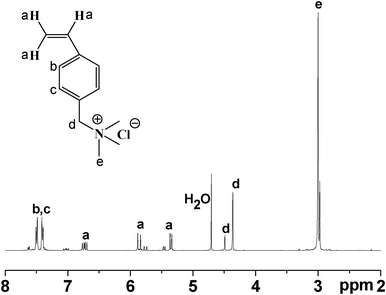
Synthesis of QVBC from 4-vinylbenzyl chloride and trimethylamine is shown in Scheme 1. The chemical structure of QVBC was characterized by 1H NMR spectroscopy. As shown in Fig. 1, the peaks around 4.30–4.56 ppm and 2.89–3.10 ppm are assigned to the chemical shifts of the protons on the methylene (–CH2–) (two peaks, d, are due to meta/para isomers respectively) and methyl groups (–CH3), respectively. It is noted that the ratio of the integrations of these two peaks is close to 2![[thin space (1/6-em)]](https://www.rsc.org/images/entities/char_2009.gif) :
:![[thin space (1/6-em)]](https://www.rsc.org/images/entities/char_2009.gif) 9, which is in accordance with the composition of the quaternary ammonium-functionalized monomer, suggesting the success of this reaction. Additionally, the peaks at 5.32–5.56 ppm, 5.74–5.98 ppm and 6.57–6.89 ppm are attributed to the three olefin proton. The peaks between 7.33 and 7.61 ppm correspond to the aromatic protons.
9, which is in accordance with the composition of the quaternary ammonium-functionalized monomer, suggesting the success of this reaction. Additionally, the peaks at 5.32–5.56 ppm, 5.74–5.98 ppm and 6.57–6.89 ppm are attributed to the three olefin proton. The peaks between 7.33 and 7.61 ppm correspond to the aromatic protons.
Synthesis and characterization of PVDF-g-QVBC copolymers
Ionic graft copolymers of PVDF-g-QVBC were synthesized via a “grafting from” ATRP method. As shown in Scheme 2, hydrophilic graft chains are growing from the fluoride units in the presence of the catalyst of CuBr. Considering the high bonding energy of C–F, the ATRP reaction is carried out in the presence of high reactive ligand of PMDETA at a high temperature of 110 °C.
 |
| | Scheme 2 Synthesis of PVDF-g-QVBC. | |
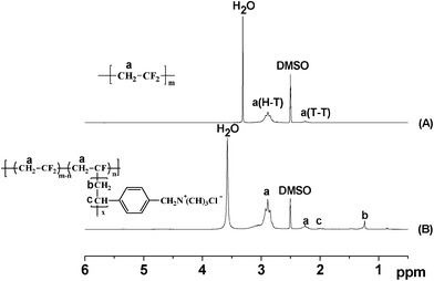
The successful graft polymerization of QVBC from PVDF backbones is confirmed by 1H NMR spectroscopy. As shown in Fig. 2, the strong peaks at 2.6 and 3.4 ppm are attributed to DMSO and water respectively. The peaks between 2.1 and 2.4 ppm are ascribed to the head-to-head (H–H) bonding arrangements of VDF. The peaks between 2.7 and 3.0 ppm are due to the head-to-tail (H–T) VDF sequences. These peaks exist in both spectra of the macroinitiator and graft copolymer. Additionally, new peaks at 1.1–1.4 ppm and 1.9–2.1 ppm attributed to protons of methylene and the benzylic protons of QVBC appear in Fig. 2(B) and indicate the success of the ATRP reaction.
To obtain a series of membranes possessing different IECs, varied amounts of QVBC were added to control the graft ratio of copolymers during ATRP reaction. The composition of the PVDF-g-QVBC copolymers, which is estimated by 1H NMR spectroscopy, is shown in Fig. 3. Specifically, the molar ratio of QVBC grafted onto PVDF backbone can be determined by integrating the methylene and benzylic protons signals of QVBC (peaks ‘b’ and ‘c’) versus the methylene protons of VDF (peak ‘a’) according to the following equation:
| |  | (5) |
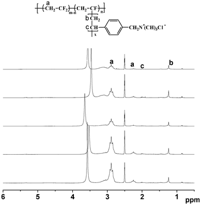 |
| | Fig. 3
1H NMR spectra of PVDF-g-QVBC with different graft ratios. From top to bottom, the molar amounts of QVBC grafts per 100 VDF units were calculated from eqn (4), respectively, 7.9, 10.3, 15.2, 19.7, 27.5. | |
Where B, C and A represent the integrals of the protons designated as ‘b’, ‘c’ and ‘a’ peaks, respectively. As shown in Table 1, the molar ratio of QVBC to VDF increases with the amounts of monomers. Additionally, theoretical IECs can be determined by the ratios according to the following equation:
| |  | (6) |
Where
m represents the molar amounts of QVBC per 100 VDF units. The data for these
copolymers are summarized in
Table 1.
| Sample |
PVDF(g) |
QVBC(g) |
QVBC/VDFa (molar ratio) |
IECtb (mmol g−1) |
|
Calculated from eqn (5)
Calculated from eqn (6)
|
| PVDF-QVBC 1.5 |
1 |
1.5 |
7.9/100 |
0.98 |
| PVDF-QVBC 2 |
1 |
2 |
10.3/100 |
1.20 |
| PVDF-QVBC 3 |
1 |
3 |
15.2/100 |
1.58 |
| PVDF-QVBC 4 |
1 |
4 |
19.7/100 |
1.86 |
| PVDF-QVBC 5 |
1 |
5 |
27.5/100 |
2.25 |
Water uptake and swelling ratio are shown in Table 2, which are closely related to IEC, play key roles in determining the ionic conductivity and mechanical properties of membranes. With the aid of water molecules, hydroxide ions can easily transport through the membrane. However, a high water uptake and large dimensional swelling usually lead to poor mechanical property of membranes. In order to investigate the influence of absorbed water molecules on membrane properties, the average number of absorbed water molecules per ionic group (λ) which takes both IEC and water uptake into account is employed in this study. Plots of water uptake and λ value versus IEC for a series of PVDF-g-QVBC membranes are shown in Fig. 4. As expected, the amount of water molecules increases exponentially with increasing ion exchange groups. The water uptake of Nafion117 is known to be 29%.26 However, as shown in Table 2, the PVDF-QVBC 2 graft membrane exhibits a similar IEC to Nafion 117 (IEC = 0.91 mmol g−1) but a lower water uptake of 16.3%. Generally, the degree of water swelling is decided by the balance between the absorbing ability of quaternary ammonium groups and the resisting ability of the hydrophobic components. As shown in Fig. 4, the water uptake and λ value increase slowly when IECs range from 0.76 to 1.55 mmol g−1. Especially, when IEC is higher than 1.55 mmol g−1, they increase remarkably. The trend is also observed in PEMs possessing block or graft structure as a result of the hydrophilic–hydrophobic phase separation.27,28
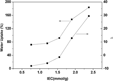 |
| | Fig. 4 Water uptake vs. IEC, and λ (the number of water molecules per quaternary ammonium group) vs. IEC for a series of PVDF-g-QVBC membranes. | |
Table 2 IEC, Wu, swelling rate, λ value, and hydroxide conductivity
| Sample |
Measured IEC (mmol g−1) |
Water uptake (%) |
Swelling rate (%) |
λ
|
Conductivity (mS cm−1) |
| PVDF-QVBC 1.5 |
0.76 |
8.1 |
1.2 |
8 |
13 |
| PVDF-QVBC 2 |
1.21 |
16.3 |
2.8 |
9 |
15 |
| PVDF-QVBC 3 |
1.55 |
34.5 |
6.6 |
13 |
25 |
| PVDF-QVBC 4 |
1.90 |
91.6 |
19.0 |
27 |
45 |
| PVDF-QVBC 5 |
2.38 |
158 |
44.1 |
36 |
36 |
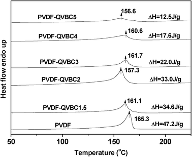
It is well known that the special architecture of graft copolymers facilitates phase separation of hydrophilic graft chains to hydrophobic backbones, which limits the membrane's swelling and serves to maintain dimensional stability of the materials. Moreover, existence of crystalline domains is also responsible for the low swelling degree of the membrane due to the semi-crystalline nature of PVDF. This point can be supported by DSC analysis of the graft copolymer AEMs. As shown in Fig. 5, each DSC endothermic curve of graft copolymers exhibits a similar melting peak with that of PVDF, suggesting the existence of crystalline domains in the membrane. Apparently, the hydrophobic crystallites could prevent membranes from swelling and maintain mechanical stability. However, the hydrophobic crystalline domains are generally considered as obstacles for ion transport. It is necessary to adjust the content of crystalline domains so as to optimize membrane properties. DSC analysis also suggests that crystalline degree can be tuned by varying the graft ratio. As shown in Fig. 5, the enthalpy of fusion of graft copolymers shows an obvious decrease with increasing graft ratio. The reason is that the flexible pendant graft chains hinder the regular aggregation of VDF units causing the decrease of crystalline degree. In order to investigate the distribution of crystalline domains and their influence on membrane properties, morphology analysis based on visible techniques of AFM and TEM is presented below.
Morphology analysis
Tapping mode AFM was employed to record phase images of quaternary ionic membranes with different graft ratios under ambient conditions. As shown in Fig. 6, spherical bright regions correspond to crystalline phases and the dark regions correspond to amorphous phase. A significant difference in size and density of crystalline domains is observed between the phase images of PVDF-QVBC 3 and PVDF-QVBC 4. In the PVDF-QVBC 3 membrane, similarly spherical crystalline domains disperse uniformly in the amorphous phase. However, when the graft ratio increases, a lower density of crystalline domains with irregular sizes is observed in the PVDF-QVBC 4 membrane. The visible morphology change is in accordance with the result from the analysis of enthalpy of fusion in Fig. 5. The crystalline degree of P(VDF-g-QVBC) copolymer decreases with increasing the amount of flexible pendant graft chains which generally hinder the regular aggregation of VDF units. To examine further, TEM analysis was employed to investigate the phase distribution of graft copolymers. In accordance with AFM images, crystalline domains of graft copolymers have regular spherical shapes when the graft ratio is low (Fig. 7a), but tend to disappear in shape when the graft ratio increases (Fig. 7b, c). Consequently, transport of hydroxide ions which usually occurs in the hydrophilic amorphous domains must show a large discrepancy on the morphology change with the amount of ionic grafts.
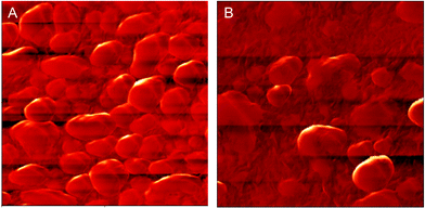 |
| | Fig. 6 AFM tapping phase images for PVDF-QVBC membrane: (A) PVDF-QVBC 3, (B) PVDF-QVBC 4; scan boxes are 2 μm × 2 μm. | |
 |
| | Fig. 7 TEM images of PVDF-g-QVBC graft copolymer membranes: (A) PVDF-g-QVBC 2, (B) PVDF-g-QVBC 3, (C) PVDF-g-QVBC 4. | |
Hydroxide conductivity
Ionic conductivity of an ion exchange membrane is vital for fuel cell application. Commonly, for alkaline fuel cells, the conductivity of hydroxide exchange membrane is required to be above 10 mS cm−1.29 In this research, all resultant membranes exhibit favorable conductivities higher than 13 mS cm−1 at 25 °C, which could meet the demand in usage.
Hydroxide conductivity of the PVDF-g-QVBC membranes was measured at 100% RH (in water) and has been expressed as a function of IEC and λ value in Fig. 8. The conductivity increases slowly for low IEC membrane and subsequently increases drastically with increasing IEC from 1.55 to 1.90 mmol g−1.30–32 This increasing trend is a result of the increased concentration of quaternary groups and volume fraction of water. Well-interconnected ion channels form due to the phase separation between hydrophobic backbones and hydrophilic side chains over a critical IEC, and facilitates hydroxide conducting. Hence, conductivity shows a sharp increase in Fig. 8. However, a further increase in IECs leads to a decrease in conductivity. It is attributed to high water uptake which dilutes the ion concentration as a similar trend which has been observed in other ionic membranes. Moreover, a profound understanding could be obtained about conductivity by probing the average number of water molecules per quaternary groups for a series of membranes. It is known that the conductivity of perfluorosulfonic acid proton exchange membranes shows a significant increase as the λ value is beyond 6.33 However, a higher λ (i.e. > 40) usually leads to a higher swelling degree. In this study, the membrane with the lowest IEC possesses a λ value of 13, which is enough for hydroxide ions to transport through membranes easily. In addition, the λ value of the membrane with the maximum conductivity is lower than that of previously reported ion exchange membranes in which the peak value of conductivity is obtained when λ value reaches 40.34 Hence, the results regarding membrane properties are consistent with the initial design strategy which aimed for high conductivity and relatively low swelling membranes.
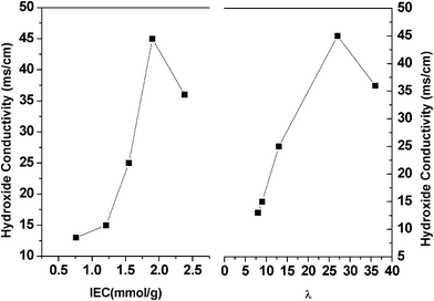 |
| | Fig. 8 Hydroxide conductivity vs. IEC and hydroxide conductivity vs. λ for the PVDF-g-QVBC membranes. | |
Thermal properties
The thermal stability of the pristine PVDF as well as the graft copolymers were studied via a TGA instrument. As shown in Fig. 9, pure PVDF shows a single degradation stage and the onset weight loss temperature is 380 °C. However, for copolymers bearing ionic groups, four distinct degradation stages are observed. Firstly, a slight mass loss at 50 °C to ∼160 °C due to the strong hydrophilicity of the quaternary groups absorbing water from surroundings. As the grafting molar ratio ranges from 7.9 to 27.5, the percentage decrease in weight increases from 2% to 12%. Secondly, elimination of quaternary groups occurs at ∼220 °C, and the loss percentage increases with the graft contents. Thirdly, degradation of side chains occurs in this stage. Finally, a large weight loss corresponding to decomposition of PVDF backbone starts at a lower temperature than pure PVDF polymers. This is due to the insert of side chains that breaks regular arrangements of backbone and results in the loss of crystalline portion. Hence, the thermal stability of copolymers reduces furthermore.
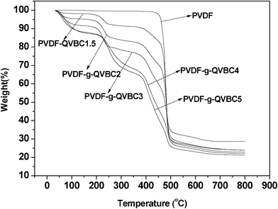 |
| | Fig. 9 TGA thermograms of PVDF and PVDF-g-QVBC copolymers at 10 °C min−1 heating rate under nitrogen atmosphere. | |
Conclusion
Soluble quarternary ammonium-containing copolymers were firstly prepared by the successful graft reaction of QVBC from PVDF via an ATRP reaction. Compared with most AEMs prepared by post-functionizalized method, those prepared from the resultant graft copolymers display superior ionic conductivity of 45 mS cm−1. The unique polymer architecture allows for microphase separation between hydrophobic and hydrophilic domains and thus the high ionic conductivity; while the crystalline domains in membranes are responsible for the thermal and mechanical stability. The optimized membranes are qualified for fuel cell application. The study presents a promising strategy to prepare AEMs with improved hydroxide conductivity from soluble quarternary ammonium-containing copolymers, and gives a pioneering understanding of the morphology–property relationship in this novel graft copolymer AEMs.
Acknowledgements
We thank the National Basic Research Program of China (No. 2012CB932800), the National Natural Science Foundation of China (nos. 21106140, 21025626, 20974106) and the Programs of Anhui Province for Science and Technology (No.11010202157) for financial support.
References
- L. Carrette, K. A. Friedrich and U. Stimming, Fuel Cells, 2001, 1, 5–39 CrossRef CAS.
- C.-Y. Wang, Chem. Rev., 2004, 104, 4727–4766 CrossRef CAS.
- A. K. Salem, F. R. A. J. Rose, R. O. C. Oreffo, X. Yang, M. C. Davies, J. R. Mitchell, C. J. Roberts, S. Stolnik-Trenkic, S. J. B. Tendler, P. M. Williams and K. M. Shakesheff, Adv. Mater., 2003, 15, 210–213 CrossRef CAS.
- T. Xu, D. Wu and L. Wu, Prog. Polym. Sci., 2008, 33, 894–915 CrossRef CAS.
- J. R. Varcoe and R. C. T. Slade, Fuel Cells, 2005, 5, 187–200 CrossRef CAS.
- J. R. Varcoe, R. C. T. Slade, G. L. Wright and Y. Chen, J. Phys. Chem. B, 2006, 110, 21041–21049 CrossRef CAS.
- G. Wang, Y. Weng, D. Chu, R. Chen and D. Xie, J. Membr. Sci., 2009, 332, 63–68 CrossRef CAS.
- T. J. Clark, N. J. Robertson, H. A. Kostalik Iv, E. B. Lobkovsky, P. F. Mutolo, H. c. D. Abrunña and G. W. Coates, J. Am. Chem. Soc., 2009, 131, 12888–12889 CrossRef CAS.
- N. J. Robertson, H. A. Kostalik, T. J. Clark, P. F. Mutolo, H. c. D. Abrunña and G. W. Coates, J. Am. Chem. Soc., 2010, 132, 3400–3404 CrossRef CAS.
- K. A. Mauritz and R. B. Moore, Chem. Rev., 2004, 104, 4535–4586 CrossRef CAS.
- K. K.D, J. Membr. Sci., 2001, 185, 29–39 CrossRef.
- J. Fang and P. K. Shen, J. Membr. Sci., 2006, 285, 317–322 CrossRef CAS.
- G. Wang, Y. Weng, D. Chu, D. Xie and R. Chen, J. Membr. Sci., 2009, 326, 4–8 CrossRef CAS.
- X. Tongwen, J. Membr. Sci., 2005, 263, 1–29 CrossRef.
- M. R. Hibbs, C. H. Fujimoto and C. J. Cornelius, Macromolecules, 2009, 42, 8316–8321 CrossRef CAS.
- H. Herman, R. C. T. Slade and J. R. Varcoe, J. Membr. Sci., 2003, 218, 147–163 CrossRef CAS.
- J. R. Varcoe, R. C. T. Slade, E. Lam How Yee, S. D. Poynton, D. J. Driscoll and D. C. Apperley, Chem. Mater., 2007, 19, 2686–2693 CrossRef CAS.
- T. N. Danks, R. C. T. Slade and J. R. Varcoe, J. Mater. Chem., 2003, 13, 712–721 RSC.
- M. R. Hibbs, M. A. Hickner, T. M. Alam, S. K. McIntyre, C. H. Fujimoto and C. J. Cornelius, Chem. Mater., 2008, 20, 2566–2573 CrossRef CAS.
- J. Yan and M. A. Hickner, Macromolecules, 2010, 43, 2349–2356 CrossRef CAS.
- E. P. Jutemar and P. Jannasch, J. Membr. Sci., 2010, 351, 87–95 CrossRef CAS.
- O. Savard, T. J. Peckham, Y. Yang and S. Holdcroft, Polymer, 2008, 49, 4949–4959 CrossRef CAS.
- Z. Zhang, L. Wu and T. Xu, J. Membr. Sci., 2011, 373, 160–166 CrossRef CAS.
- K. Matsumoto, T. Higashihara and M. Ueda, Macromolecules, 2009, 42, 1161–1166 CrossRef CAS.
- K. Matyjaszewski, P. J. Miller, N. Shukla, B. Immaraporn, A. Gelman, B. B. Luokala, T. M. Siclovan, G. Kickelbick, T. Vallant, H. Hoffmann and T. Pakula, Macromolecules, 1999, 32, 8716–8724 CrossRef CAS.
- E. M. W. Tsang, Z. Zhang, A. C. C. Yang, Z. Shi, T. J. Peckham, R. Narimani, B. J. Frisken and S. Holdcroft, Macromolecules, 2009, 42, 9467–9480 CrossRef CAS.
- Z. Zhang, E. Chalkova, M. Fedkin, C. Wang, S. N. Lvov, S. Komarneni and T. C. M. Chung, Macromolecules, 2008, 41, 9130–9139 CrossRef CAS.
- J. Ding, C. Chuy and S. Holdcroft, Chem. Mater., 2001, 13, 2231–2233 CrossRef CAS.
- J. Wang, S. Li and S. Zhang, Macromolecules, 2010, 43, 3890–3896 CrossRef CAS.
- Y. Yang, Z. Shi and S. Holdcroft, Macromolecules, 2004, 37, 1678–1681 CrossRef CAS.
- Z. Shi and S. Holdcroft, Macromolecules, 2005, 38, 4193–4201 CrossRef CAS.
- L. Rubatat, Z. Shi, O. Diat, S. Holdcroft and B. J. Frisken, Macromolecules, 2005, 39, 720–730 CrossRef.
- C. Gavach, G. Pamboutzoglou, M. Nedyalkov and G. Pourcelly, J. Membr. Sci., 1989, 45, 37–53 CrossRef CAS.
- T. J. Peckham, J. Schmeisser, M. Rodgers and S. Holdcroft, J. Mater. Chem., 2007, 17, 3255–3268 RSC.
|
| This journal is © The Royal Society of Chemistry 2012 |
Click here to see how this site uses Cookies. View our privacy policy here. 


![[thin space (1/6-em)]](https://www.rsc.org/images/entities/char_2009.gif) :
:![[thin space (1/6-em)]](https://www.rsc.org/images/entities/char_2009.gif) 9, which is in accordance with the composition of the quaternary ammonium-functionalized monomer, suggesting the success of this reaction. Additionally, the peaks at 5.32–5.56 ppm, 5.74–5.98 ppm and 6.57–6.89 ppm are attributed to the three olefin proton. The peaks between 7.33 and 7.61 ppm correspond to the aromatic protons.
9, which is in accordance with the composition of the quaternary ammonium-functionalized monomer, suggesting the success of this reaction. Additionally, the peaks at 5.32–5.56 ppm, 5.74–5.98 ppm and 6.57–6.89 ppm are attributed to the three olefin proton. The peaks between 7.33 and 7.61 ppm correspond to the aromatic protons.
