Direct assembly of tin–MWCNT 3D-networked anode for rechargeable lithium ion batteries†
Seung-Deok
Seo
,
Gwang-Hee
Lee
,
Ah-Hyeon
Lim
,
Kyung-Mi
Min
,
Jae-Chan
Kim
,
Hyun-Woo
Shim
,
Kyung-Soo
Park
and
Dong-Wan
Kim
*
Department of Materials Science and Engineering, Ajou University, Suwon 443-749, Korea. E-mail: dwkim@ajou.ac.kr
First published on 22nd February 2012
Abstract
Nanocomposites of Sn nanoparticle–multiwalled carbon nanotubes (MWCNTs) were prepared by simple two-step electrochemical processes. First, acid-functionalized MWCNTs were electrophoretically deposited on a stainless steel substrate. Sn nanoparticles decorated on the MWCNTs were prepared by the electrodeposition of a SnCl4 aqueous solution on the pre-deposited MWCNT-film layer. The structure of the newly fabricated Sn-MWCNT composite was characterized by X-ray diffraction (XRD), scanning electron microscopy (SEM), and high-resolution transmission electron microscopy (HRTEM). The electrochemical performance of the composite was evaluated by cyclic voltammetry and galvanostatic cycling. The as-deposited composite film shows the size of the uniformly dispersed Sn particles, ranging from few to several tens of nanometres, as a function of the deposition time. The composite shows electrochemical performance that is superior to that of a pure Sn nanoparticle anode.
1. Introduction
Rechargeable Li-ion batteries (LiBs) were invented and developed to meet consumer and industrial demand. They are used for many purposes, ranging from portable electronics such as cellular phones, laptop computers, electric vehicles, and stationary energy storage systems. Carbonaceous materials are generally used as an anode material in lithium ion batteries. It is a very cheap and reliable material for LiB electrodes. Lithium ions intercalate between the graphitic layers in the anode (Li + 6C ↔ LiC6; theoretical capacity of 372 mA h g−1).1 This reaction results in little change in the dimensions and the stacking order stability during lithium intercalation/de-intercalation, thereby displaying stable cycle performance. However, the most prominent weakness of carbonaceous materials is their low gravimetric energy density. The low density is not adequate to satisfy the requirements of the diverse market demand for modern devices, and hence various materials have been proposed to substitute carbonaceous materials in order to meet the high energy and high power density demand.2Over the past couple of years, a considerable number of studies have been conducted on the development of pure metal anodes made of metals such as Sn, Ge, and Si that are capable of forming alloys with lithium.3 Conventional commercialized carbon anodes undergo chemical reactions with lithium that involve the intercalation of lithium in the graphitic layer. In the case of metal anodes, lithium ions are inserted into metallic matrices, and 4.4 moles of Li ion form intermetallic bonds with each metal atom (M + 4.4 Li ↔ Li4.4M).4 This alloying reaction is more advantageous than the intercalation reaction, especially in the case of Sn that undergoes an alloying reaction with Li and has a relatively high specific capacity of about 994 mA h g−1 (Sn + 4.4 Li ↔ Li4.4Sn), which is two and a half times more than that of carbon. It guarantees an energy density higher than that of the conventional graphite anode. However, metallic Sn anode has the major drawback of dramatically expanding/shrinking in volume when undergoing the alloying reaction with lithium (∼358%).5
It is widely known that volume expansion generates mechanical stress causing cracking and pulverization of the active material after a few cycles; volume expansion also leads to an irreversible decrease in capacity and poor cyclability.6 For these reasons, numerous attempts have been made to overcome this problem of acute decrease in capacity by using various solutions such as Sn–M intermetallic alloys,7–11 construction of various types of nanostructures,12,13 amorphous Sn composites,14 Sn–carbonaceous material composites,15–21 formation of Sn-based oxides,22,23 coating with amorphous carbon,24 and formation of active–inactive structures.25 In recent times, the most frequently reported candidates for anode materials are Sn-based carbonaceous composite materials. Carbon is widely known as a cheap and common material to make composites. Moreover, it can act as an efficient electron pathway, a stress-relaxation buffer layer, and a dispersion medium for active materials. Many studies have reported about the aforementioned aspects of Sn-based carbonaceous composite materials.15–21
Most Sn–CNT composite electrodes reported in the literature including the recent review paper by Kamali and Fray were prepared using Sn coating on MWCNTs by soaking a SnCl2 solution in the presence of reducing agents.26,27 These powder-based Sn-CNT composite materials should need a cumbersome procedure for electrode preparation: mixing with conductive additives (e.g. carbon black) and polymer binders. In addition, the cycle stability could not be properly improved, possibly due to the local aggregation of Sn nanoparticles and irregular formation of larger Sn particles during the chemical reduction process.
In this study, we applied for the first time a two-step electrodeposition process: (1) initial electrophoretic deposition of MWCNTs directly onto the current collector (stainless steel foil) and then (2) electrolytic deposition of Sn (cathodic reduction) for the fabrication of Sn–MWCNT nanocomposite electrodes at room temperature. Furthermore, a time-dependent structural change and crystal evolution were observed by electron microscopy and X-ray diffraction. The electrochemical characterization of this Sn-MWCNT 3D-networked nanocomposite was also performed by galvanostatic cycling and cyclic voltammetry.
2. Experimental details
2.1 Fabrication of MWCNT and Sn-MWCNT films
First, 2 g of pristine MWCNTs (CM 100, Hanwha Nanotech) was added to a 3![[thin space (1/6-em)]](https://www.rsc.org/images/entities/char_2009.gif) :
:![[thin space (1/6-em)]](https://www.rsc.org/images/entities/char_2009.gif) 1 mixture of H2SO4 and HNO3 (98%, 70%, Samchun Chem.) to form carboxylic functional group on the MWCNT surface. Then, the mixture was heated with vigorous stirring and allowed to stand at 110 °C for 30 min. After the acid treatment, the MWCNTs were washed with deionized water and absolute ethanol and filtered through a PVDF membrane (Durapore, 0.22 μm Millipore); the washing and filtering were performed several times for the purification of acidic residues. The washed MWCNTs were first dried in a N2 stream at room temperature and then dried for 8 h in a vacuum oven at 80 °C. To form a MWCNT film on a substrate, 20 mg of functionalized MWCNTs and 4 mg of Ni(NO3)2·5H2O (Samchun Chem.) were added to 50 ml of isopropyl alcohol and dispersed by a bath-type ultrasonicator for several hours. Afterward, cathodic electrophoretic deposition of the well-dispersed MWCNT suspension was performed under a constant voltage of 100 V for 2 min with a 304-stainless-steel foil (0.03 mm thick, Alfa) negative electrode (cathode) and an Al foil (anode) which were supported by slide glasses. The electrophoretically deposited MWCNT films were dried at 80 °C by keeping them in a vacuum oven for 4 h.
1 mixture of H2SO4 and HNO3 (98%, 70%, Samchun Chem.) to form carboxylic functional group on the MWCNT surface. Then, the mixture was heated with vigorous stirring and allowed to stand at 110 °C for 30 min. After the acid treatment, the MWCNTs were washed with deionized water and absolute ethanol and filtered through a PVDF membrane (Durapore, 0.22 μm Millipore); the washing and filtering were performed several times for the purification of acidic residues. The washed MWCNTs were first dried in a N2 stream at room temperature and then dried for 8 h in a vacuum oven at 80 °C. To form a MWCNT film on a substrate, 20 mg of functionalized MWCNTs and 4 mg of Ni(NO3)2·5H2O (Samchun Chem.) were added to 50 ml of isopropyl alcohol and dispersed by a bath-type ultrasonicator for several hours. Afterward, cathodic electrophoretic deposition of the well-dispersed MWCNT suspension was performed under a constant voltage of 100 V for 2 min with a 304-stainless-steel foil (0.03 mm thick, Alfa) negative electrode (cathode) and an Al foil (anode) which were supported by slide glasses. The electrophoretically deposited MWCNT films were dried at 80 °C by keeping them in a vacuum oven for 4 h.
The next step was the electrochemical deposition of Sn nanoparticles onto the as-prepared MWCNT films to form Sn–MWNCT composite films. The MWCNT films were directly used as the cathode, an Al foil was used as the anode in a SnCl4 aqueous solution under a constant current of 50 mA for various preset times. The Sn–MWNCT composite films were washed several times with deionized water and ethanol. The films finally obtained were dried at 80 °C in a vacuum oven for 4 h under conditions similar to those in the case of the electrophoretically deposited MWCNT films.
2.2 Microstructural/electrochemical characterization of films
The properties and structural morphologies of the prepared films were characterized and analysed using X-ray diffraction (XRD; model D/MAX-2500V/PC, Rigaku, Tokyo, Japan), field emission scanning electron microscopy (FESEM; model JSM-6330F, JEOL, Tokyo, Japan), and high resolution transmission electron microscopy (HRTEM; model JEM-2100, JEOL, Tokyo, Japan). In addition, the weight of the deposited film was measured by a microbalance (0.1 μg, model UMT5, Mettler Toledo, Greifensee, Swiss). The electrochemical performance of the prepared films was evaluated by Swagelok-type half-cells. The Sn-MWCNT composite fabricated on the stainless steel substrate was punched for performing the direct test, having a diameter of 10 mm. The half-cells were assembled using the punched Sn–MWCNT electrode as the positive electrode (cathode), a Li metal foil as the negative electrode (anode), a separator film (Celgard 2400), and a liquid electrolyte (ethylene carbonate and dimethyl carbonate (1![[thin space (1/6-em)]](https://www.rsc.org/images/entities/char_2009.gif) :
:![[thin space (1/6-em)]](https://www.rsc.org/images/entities/char_2009.gif) 1 by volume) with 1.0 M LiPF6, Techno Semichem Co., Ltd., Seongnam, South Korea). The assembled cells were galvanostatically cycled between 2.5 and 0.01 V using an automatic battery cycler (WBCS 3000, WonaTech, Seoul, Korea) and their cyclic voltammetry measurements were carried out at a scanning rate of 0.3 mV s−1.
1 by volume) with 1.0 M LiPF6, Techno Semichem Co., Ltd., Seongnam, South Korea). The assembled cells were galvanostatically cycled between 2.5 and 0.01 V using an automatic battery cycler (WBCS 3000, WonaTech, Seoul, Korea) and their cyclic voltammetry measurements were carried out at a scanning rate of 0.3 mV s−1.
3. Result and discussion
Fig. 1a shows a typical method of synthesizing Sn–MWCNT nanocomposite films. The first step is the electrophoretic deposition process using the suspension containing MWCNTs functionalized via acid treatment (f-MWCNT) to form a MWCNT film on stainless steel (SS) foil substrates (Fig. 1b left).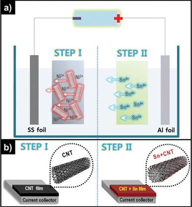 | ||
| Fig. 1 Schematic representation of (a) the two-step deposition method of Sn-MWCNT nanocomposite fabrication and (b) a deposited MWCNT film (left), and a Sn–MWCNT nanocomposite film (right). | ||
For the fabrication of the nanocomposite film, the next process was followed by the electrolytic deposition of Sn (cathodic reduction, Fig. 1b right).
Generally, pristine MWCNTs do not have electrophoretic mobility and a considerable degree of dispersion, so some techniques are applied for the surface functionalization of the MWCNTs.28–30 Strong acids such as H2SO4, HNO3, or a mixture of the two can break the C–C bond on the MWCNT surface. Further, the MWCNTs produce a carboxylate anion group (–COO−) at the site of the broken C–C bond, and it eventually induces negative charge to the MWCNT surface.31
As shown in Fig. 2, pristine MWCNTs are almost charge-less but the f-MWCNTs have a significantly high negative value of zeta potential (ζ), and the high value of zeta potential is clearly explained by the formation of the surface carboxylate anion group. Hu et al. reported about the influence of ζ on the dispersibility of single walled CNTs.32 This phenomenon has an enormous effect on the stable dispersion of MWCNTs in water and other polar solvents, because of the existence of a repulsion force between the negative charges on the surface of every MWCNT. Finally, an electrostatically stable dispersion was obtained because of this repulsion force. According to our experimental observation, f-MWCNTs form a very stable dispersion in isopropyl alcohol (IPA), and the dispersion lasts even for several months. For cathodic electrophoretic deposition, each particle should have a positive charge on its surface. Therefore, dissolved Ni2+ ions play an important role in moving the MWCNTs toward the SS substrate that acts as the cathode (negative electrode). The Ni2+-dissolved f-MWCNT suspension has a positive ξ value (+47.6 mV), and this observation explains the role of the Ni2+ well.
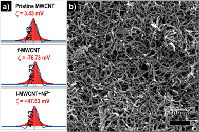 | ||
| Fig. 2 Zeta potential value of (a) pristine MWCNTs, functionalized MWCNTs, and functionalized MWCNTs with Ni salt dispersed in isopropyl alcohol. (b) FESEM image of the as-electrophoretically-deposited MWCNTs on a SS substrate. | ||
In order to find the optimal parameters for homogeneous deposition of MWCNTs, the electrophoretic deposition was carried out at various conditions. Relatively low voltage resulted in low density and non-uniform depositions, which did not adhere to the substrate. At higher voltage or longer deposition times, the excessive aggregation of MWCNTs and poorer homogeneity of films were observed. Very uniform, ∼2.4 μm thick MWCNT coatings were produced when the electrophoretic deposition was carried out at 100 V for 2 min, as shown in Fig. S1 (ESI†). Fig. 2b shows a surface view of an electrophoretically deposited uniform MWCNT film on SS substrates by using a well-dispersed MWCNT suspension.
Thereafter, the second step is the electrodeposition of Sn nanoparticles on the MWCNT films by using tin(IV) chloride aqueous solution. To find the microstructural changes in the electrodeposited Sn–MWCNT composites, time-dependent experiments were carried out. Fig. S2 (ESI†) shows a voltage–time curve for the deposition of Sn on MWCNT under a constant current of 50 mA. After ∼1 min, the voltage stabilized at ∼900 mV up to 17 min.
Fig. 3 shows a typical FESEM image of the Sn–MWCNT nanocomposites formed under the same value of deposition current (50 mA) but for different durations. As shown in the image, a Sn crystal was grown from a size of a few nanometres to a size of the order of sub-microns. Fig. 3a shows the Sn–MWCNT composite where Sn was deposited for 1 min. In comparison to the deposited pure MWCNT film (Fig. 2b), Fig. 3a shows a very small amount of Sn nanoparticles having a size of few nanometres that cannot be identified accurately from the low-magnification image. In a magnified view, we can observe that there exists a clear difference in the microstructures of the Sn-deposited MWCNT film compared to the pure MWCNT film as the former has a rougher surface morphology. This observation was confirmed by the typical cross-sectional SEM image of Sn–MWCNT films (Fig. S3, ESI†). Fig. 3b–d also show Sn–MWCNT films for various deposition times. These films were deposited for 3, 7, and 10 min, respectively, and these figures help us define the time-dependent crystal structure evolution of Sn. Fig. 3b, where the composite was deposited for 3 min, shows that there was no significant difference compared to Fig. 3a apart from a rougher surface and the existence of more crystals than in Fig. 3a.
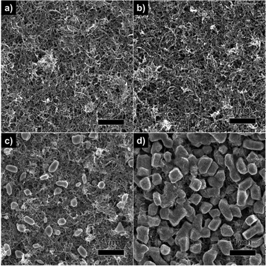 | ||
| Fig. 3 FESEM images of Sn–MWCNT nanocomposite films deposited under with a constant current for different time durations: (a) 1 min, (b) 3 min, (c) 7 min, and (d) 10 min. | ||
As the deposition time increased, no striking change in the morphology of Sn on the MWCNT bundles was observed, but some irregular-Sn particles were precipitated on the MWCNT layer (Fig. 3c). With a further increase in the deposition time, precipitated particles tend to become larger and eventually, the grown particles covered the MWCNT layer as shown in Fig. 3d. This morphological evolution of nanocrystalline Sn indicates that the dissolved Sn cations attracted and migrated toward the opposite electric charge under the effect of an electric field. Then, the attracted cations were reduced by the electrons on the cathode, thus forming crystalline Sn.
| SnCl4 + H2O → Sn4+ + 4Cl− | (1) |
| Sn4+ + 4e− → Sn0 | (2) |
The crystallization and the growth of Sn by electrochemical reduction were also examined using X-ray diffraction (XRD). Fig. 4 depicts the XRD patterns of the pure MWCNT and Sn–MWCNT composites on an SS substrate. As shown in Fig. 3, the pure MWCNT film on the substrate shows only the broad peak of MWCNTs at about 26° and the peaks of the substrate at about 44, 50, and 75°. The peak around 26° was indexed to graphite (002). By electrochemical reduction, Sn was precipitated and grown for durations ranging from 1 min to 10 min. According to our observations, deposition for 1 and 3 min results in the generation of very small traces of particular planes of Sn and the appearance of the pure MWCNT peak. The appearance of the pure MWCNT peak can be explained by the existence of Sn crystals on the MWCNT film in very small amounts that are so small that they cannot be identified clearly in low magnification. With an increase in deposition time, the main peaks of metallic Sn (200) and Sn (101) increased and other relatively small peaks were detected.
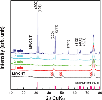 | ||
| Fig. 4 XRD patterns of Sn–MWCNT nanocomposite films deposited with the same current for different durations. | ||
The appearance of small peaks can be explained by the irregular-shaped particles covering the MWCNT layer in FESEM images. All the peaks perfectly correspond to the β-Sn (tetragonal, I41/amd) reference (JCPDS# 04-0673) and show that the deposited MWCNT film remained under whole deposition conditions.
More detailed microstructural and morphological investigations were carried out. A Sn–MWCNT nanocomposite (50 mA/7 min) sample, shown in Fig. 5, was analysed by TEM, HRTEM, and fast Fourier transform (FFT). The low magnification view in Fig. 5a shows precipitated Sn nanoparticles decorated on the surface of MWCNTs; precipitated Sn particles can be clearly distinguished by comparing them with the TEM image of the as-prepared f-MWCNT and Sn-MWCNT films deposited for 3 min (Fig. S4, ESI†). The anchoring of Sn nanoparticles was also confirmed by using the FFT patterns in Fig. 5b. The Sn {101} pattern was indexed in FFT from the whole region of 5a.
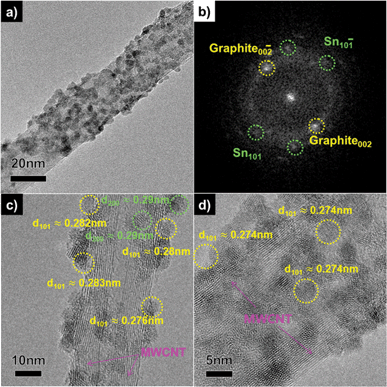 | ||
| Fig. 5 TEM image of a Sn–MWCNT nanocomposite film deposited for 7 min. (a) A low-magnification view, (b) an FFT image, and (c, d) HRTEM images of a single strand of the composite. | ||
Furthermore, the particle size, morphologies, and crystallinity of the composite shown in Fig. 5c and d were determined by using HRTEM. There are single strands of the Sn-MWCNT composite having a diameter of 20 nm. The Sn nanoparticles were uniformly precipitated on the MWCNT surface. As shown in Fig. 5c, Sn (101), Sn (200) nanoparticles having d-spacing values of about 0.28–0.29 nm were observed. The nanoparticles have sizes of about 5–10 nm, and the indexed planes correspond to the XRD result and the β-Sn reference. Fig. 5d shows another region of the same sample. It also shows the deposited nanoparticles indexed to Sn (101). In addition, to determine the correlation between the deposition time and the morphology evolution, a sample (50 mA/10 min) was also analyzed. Fig. S5 (ESI†) shows the TEM image of this sample that had a prolonged deposition time. The composites consisted of two types of Sn particles; nanoparticles (5–10 nm) on MWCNTs and sub-micron particles (100–500 nm), similar to those represented in Fig. 5.
From this observation, Sn nanoparticles were preferentially formed on the surface of MWCNTs and then irregularly nucleated Sn particles were concentrated and grew fast during excess deposition time, covering the surface of the MWCNT substrate.
Fig. 6 shows the cyclic voltammetry (CV) curves of a Sn–MWCNT composite anode deposited for 7 min within a voltage window of 2.5–0.01 V for ten cycles at a scan rate of 0.3 mV s−1. As shown in Fig. 6, three major pairs of peaks (0.6 V/0.82 V, 0.48 V/0.77 V, and 0.29 V/0.69 V) were observed in the CV profile. The appearance of these peaks matches with that given in other reports on the Sn anode24,33 and the tested commercial Sn nanopowder's peaks are shown in Fig. S6 (ESI†). In comparison to the CV profiles of pure Sn electrodes, the Sn–MWCNT composite shows larger redox peaks and a slower decrease in the peak intensity. This observation can be explained by the smaller particle size of Sn and efficient electron pathway by the incorporation of MWCNTs in Sn–MWCNT nanocomposites.34
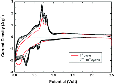 | ||
| Fig. 6 Cyclic voltammogram of the Sn–MWCNT nanocomposite film deposited for 7 min. The red line represents the first cycle and the black lines denote the subsequent cycles. | ||
We performed galvanostatic cycling of the synthesized Sn–MWCNT composites. Tests were carried out in the voltage range 2.5–0.01 V with a constant current of 0.2 C (198.6 mA h g−1, according to the relation 1C = 993 mA h g−1). Fig. 7a depicts a plot of specific capacity versus the cycle number of a pure MWCNT film, a commercial Sn nanoparticle, and a Sn-MWCNT composite deposited for 7 min. The pure MWCNT shows a high specific capacity of 1600 mA h g−1 at the first discharge, but the first charge capacity is about 700 mA h g−1 (Fig. S7a†). After a large irreversible reaction in the first cycle, the irreversibility gradually decreased during the cycle and the specific capacity also decreased gradually. The commercial Sn-nanoparticle electrode shows a higher initial capacity but has poor capacity retention, as shown in Fig. S7b†. After about 10 cycles, the capacity of the Sn nanoparticle was just 100 mA h g−1, and this value is much lower than its theoretical capacity (994 mA h g−1).
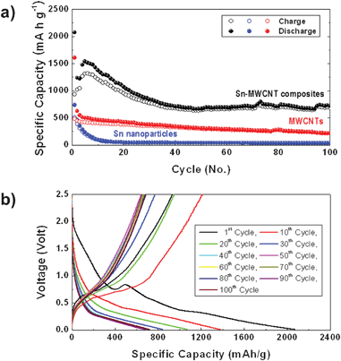 | ||
| Fig. 7 (a) Cycle performance of Sn–MWCNT, MWCNT, and commercial Sn nanoparticle electrodes (filled circles: discharge; open circles: charge). (b) Galvanostatic voltage-specific capacity profiles of Sn–MWCNT electrodes. | ||
In comparison, the Sn–MWCNT composite electrode shows better cycle performance maintaining higher reversible capacity. At the first discharge, the composite shows a high specific capacity of 2100 mA h g−1 but a decreased first charge capacity of about 900 mA h g−1 (Fig. 7b).
This irreversibility originates from the formation of a solid–electrolyte interface film on the MWCNTs and Sn nanoparticles. After the first cycle, the discharge–charge capacity gradually fades until the 40th cycle. After 40 cycles and up to 100 cycles, the cyclic behavior and irreversibility stabilized around 700 mA h g−1. Furthermore, we tested the Sn–MWCNT composite electrode prepared under different synthesis conditions. The cycle-capacity plot is depicted in Fig. S8 (ESI†), and we can observe that samples prepared by deposition for 7 min have the most stable cycle performance owing to their uniform microstructure without excessive sub-micron Sn particles.
As mentioned above, Sn has a very large theoretical capacity (994 mA h g−1) as one mole of Sn can store 4.4 moles of Li but the drastic volume variation (∼358%) during Li-ion uptake/removal induces mechanical strain, thereby leading to poor cycle stability. The detailed mechanism of enhanced electrochemical performance in the aforementioned Sn–MWCNT nanocomposite electrodes can be explained through the cooperative contribution of each material and nanostructuring: (1) the uniform formation of Sn nanoparticles (5–10 nm) can realize efficient Li-alloying reactions due to short diffusion length. (2) In addition, the assembled-nanoscale network by the 1D MWCNT with good electrical conductivity can provide high quality electronic transport pathways during cycling. (3) Furthermore, this 3D extended network with larger surface area creates favorable open space in the nanocomposite structure, which helps to alleviate the effect of huge volume change during Li-alloying/de-alloying process, as shown in Fig. 8.27,35 These advantageous geometrical features have enabled Sn-MWCNT nanocomposite electrodes to demonstrate superior electrochemical performance.
 | ||
| Fig. 8 Schematic illustration of the Li-alloying/de-alloying process in Sn-MWCNT nanocomposite electrodes. | ||
Conclusions
Directly assembled Sn-MWCNT nanocomposites were successfully fabricated on current collectors by using simple electrochemical procedures with various deposition times. The anode for the lithium ion battery was fabricated without any binder used in a conventional electrode forming process. The uniformly distributed Sn-nanoparticles on MWCNTs were identified using XRD, SEM, and TEM. The composite with an optimized deposition time exhibited an enhanced discharge capacity of about 730 mA h g−1. These enhanced performances were caused by the additional electron conducting pathway through the 3D MWCNT networks and the uniformly distributed nano-sized Sn particles providing efficient Li reactivity.Acknowledgements
This work was supported by the National Research Foundation of Korea Grant funded by the Korean Government (MEST) (NRF-2011-0030300 and 2011-0019119).References
- K. Tatsumi, N. Iwashita, H. Sakaebe, H. Shioyama and S. Higuchi, J. Electrochem. Soc., 1995, 142, 716 CrossRef CAS.
- B. Scrosati and J. Garche, J. Power Sources, 2010, 195, 2419 CrossRef CAS.
- C. M. Park, J. H. Kim, H. Kim and H. J. Sohn, Chem. Soc. Rev., 2010, 39, 3115 RSC.
- D. Larcher, S. Beattie, M. Morcrette, K. Edstrom, J. C. Jumas and J. M. Tarascon, J. Mater. Chem., 2007, 17, 3759 RSC.
- J. T. Vaughey, J. O'Hara and M. M. Thackeray, Electrochem. Solid-State Lett., 2000, 3, 13 CrossRef CAS.
- C. K. Chan, H. Peng, G. Liu, K. Mcilwrath, X. F. Zhang, R. A. Huggins and Y. Cui, Nat. Nanotechnol., 2007, 3, 31 CrossRef.
- J. Yang, M. Wachtler, M. Winter and J. O. Besenhard, Electrochem. Solid-State Lett., 1999, 2, 161 CrossRef CAS.
- M. Wachtler, J. O. Besenhard and M. Winter, J. Power Sources, 2001, 94, 189 CrossRef CAS.
- J. Hassoun, S. Panero, P. Simon, P. L. Taberna and B. Scrosati, Adv. Mater., 2007, 19, 1632 CrossRef CAS.
- J. Zhang and Y. Xia, J. Electrochem. Soc., 2006, 153, A1466 CrossRef CAS.
- L. Xue, Z. Fu, Y. Yao, T. Huang and A. Yu, Electrochim. Acta, 2010, 55, 7310 CrossRef CAS.
- L. Bazin, S. Mitra, P. L. Taberna, P. Poizot, M. Gressier, M. J. Menu, A. Barnabé, P. Simona and J. M. Tarascon, J. Power Sources, 2009, 188, 578 CrossRef CAS.
- Y. Yu, L. Gu, X. Lang, C. Zhu, T. Fujita, M. Chen and J. Maier, Adv. Mater., 2011, 23, 2443 CrossRef CAS.
- L. Y. Beaulieu, K. C. Hewitt, R. L. Turner, A. Bonakdarpour, A. A. Abdo, L. Christensen, K. W. Eberman, L. J. Krause and J. R. Dahn, J. Electrochem. Soc., 2003, 150, A149 CrossRef CAS.
- Y. Wang, M. Wu, Z. Jiao and J. Y. Lee, Chem. Mater., 2009, 21, 3210 CrossRef CAS.
- G. Cui, Y. Hu, L. Zhi, D. Wu, I. Lieberwirth, J. Maier and K. Mullen, Small, 2007, 3, 2066 CrossRef CAS.
- Y. Wang, J. Y. Lee and T. C. Deivara, J. Electrochem. Soc., 2004, 151, A1804 CrossRef CAS.
- G. Wang, B. Wang, X. Wang, J. Park, S. Dou, H. J. Ahn and K. W. Kim, J. Mater. Chem., 2009, 19, 8378 RSC.
- G. Derrien, J. Hassoun, S. Panero and B. Scrosati, Adv. Mater., 2007, 19, 2336 CrossRef CAS.
- Y. Yu, L. Gu, C. Wang, A. Dhanabalan, P. A. van Aken and J. Maier, Angew. Chem., Int. Ed., 2009, 48, 6485 CrossRef CAS.
- J. Hassoun, K. S. Lee, Y. K. Sun and B. Scrosati, J. Am. Chem. Soc., 2011, 133, 3139 CrossRef CAS.
- Y. D. Ko, J. G. Kang, J. G. Park, S. J. Lee and D. W. Kim, Nanotechnology, 2009, 20, 455701 CrossRef.
- L. Yuan, Z. P. Guo, K. Konstantinov, H. K. Liu and S. X. Dou, J. Power Sources, 2006, 159, 345 CrossRef CAS.
- M. J. Noh, Y. J. Kwon, H. J. Lee, J. P. Cho, Y. J. Kim and M. G. Kim, Chem. Mater., 2005, 17, 1926 CrossRef CAS.
- J. G. Kang, J. G. Park and D. W. Kim, Electrochem. Commun., 2010, 12, 307 CrossRef CAS.
- A. R. Kamali and D. J. Fray, Rev. Adv. Mater. Sci., 2011, 27, 14 CAS.
- Z. P. Guo, Z. W. Zhao, H. K. Liu and S. X. Dou, Carbon, 2005, 43, 1392 CrossRef CAS.
- M. S. P. Shaffer, X. Fan and A. H. Windle, Carbon, 1998, 36, 1603 CrossRef CAS.
- B. J. C. Thomas and A. R. Boccaccini, J. Am. Ceram. Soc., 2005, 88, 980 CrossRef CAS.
- R. Bandyopadhyaya, E. Nativ-Roth, O. Regev and R. Yerushalmi-Rozen, Nano Lett., 2002, 2, 25 CrossRef CAS.
- A. R. Boccaccini, J. Cho, J. A. Roether, B. J. C. Thomas, E. J Minay and M. S. P. Shaffer, Carbon, 2006, 44, 3149 CrossRef CAS.
- H. Hu, A. Yu, E. Kim, B. Zhao, M. E. Itkis, E. Bekyarova and R. C. Haddon, J. Phys. Chem. B, 2005, 109, 11520 CrossRef CAS.
- X. Zhaoa, Z. Xiab and D. Xia, Electrochim. Acta., 2010, 55, 6004 CrossRef.
- S. D. Seo, Y. H. Jin, S. H. Lee, H. W. Shim and D. W. Kim, Nanoscale Res. Lett., 2011, 6, 307 CrossRef.
- W. X. Chen, J. Y. Lee and Z. Liu, Carbon, 2003, 41, 959 CrossRef CAS.
Footnote |
| † Electronic Supplementary Information (ESI) available: HRTEM images of pristine MWCNTs and the Sn–MWCNT nanocomposite deposited for 3 min, TEM image of the Sn–MWCNT nanocomposite film deposited for 10 min, cyclic voltammogram of commercial Sn nanoparticles, cyclic performances of Sn-MWCNT nanocomposites deposited with the same current for different durations. See DOI: 10.1039/c2ra00943a/ |
| This journal is © The Royal Society of Chemistry 2012 |
