A one-pot organic–inorganic co-assembling route to ordered mesoporous carbons with cubic and bimodal pore structures†‡
Chun-Chiang
Ting
,
Yu-Chi
Pan
,
Shanmugam
Vetrivel
,
Diganta
Saikia
and
Hsien-Ming
Kao
*
Department of Chemistry National Central University Chung-Li, Taiwan 32054. E-mail: hmkao@cc.ncu.edu.tw; Fax: +886-3-4227664
First published on 1st February 2012
Abstract
Highly ordered cubic mesoporous carbons with the cubic I4132 mesostructure have been synthesized via organic–inorganic self-assembly of tetraethoxysilane (TEOS), triblock copolymer Pluronic P123, and sucrose under acidic conditions.
Ordered mesoporous carbons (OMCs) have attracted great interest in many areas of modern science and technology due to their remarkable structural properties, such as high surface areas, large pore volumes, and uniform pore sizes.1 A frequently used approach to fabricate OMCs is the nanocasting strategy,2 which utilizes mesoporous silica as the hard template to fill with a carbon precursor, followed by high temperature carbonization with subsequent removal of the silica framework by HF or NaOH. However, the procedures employed by nanocasting, such as the prerequisite of the hard mesostructured silica template, followed by repeated impregnating of carbon sources, are time-consuming and tedious. It has also been demonstrated that accurate control of the interaction between an organic precursor and a hard silica template is critical for nanocasting synthesis.3 These disadvantages make the nanocasting pathways complicated and thus industrially unfeasible.
In view of complicated synthesis procedures associated with the nanocasting approach, the development of an effective synthesis route for the direct formation of OMCs is highly desirable. Recently, much effort has been devoted to the direct synthesis of OMCs. Moriguchi et al.4 reported a new method for the synthesis of OMCs by in situpolymerization of divinylbenzene in a hexagonally arrayed micelle/silicated nanocomposite. Lee et al. reported that OMCs can be directly obtained from carbonization of P123/phenol-resin/silica nanocomposites.5 An alternative way to synthesize OMCs is to use the so called evaporation induced self-assembly method (EISA). For example, Liang et al. developed a stepwise assembly approach to prepare mesoporous carbon films.6 Tanaka et al. used resorcinol/formaldehyde and triethylorthoacetate as the carbon co-precursor to prepare mesoporous carbon thin films via direct carbonization.7 Recently, Zhao and co-workers demonstrated a reproducible synthesis of mesoporous polymers and carbons viaEISA of phenolic resins and Pluronic P123.8,9 Although the EISA method is a facile synthetic pathway, it is difficult to scale-up the production of ordered mesoporous carbons in a quantitative way. A short and facile synthetic procedure needs to be developed in order to extend the applications of OMCs.
In parallel to nanocasting, the self-assembly method is a one-pot synthesis route to synthesize OMCs directly via the use of surfactant both as the structure-directing agent and the carbon source. Kim et al.10 have used Pluronic P123 both as the carbon precursor and as the structure-directing agent to prepare hexagonal OMCs via carbonization of silica/P123 composites. Later, Liet al.11 reported that sucrose can be added to improve the carbon yield of OMCs. Here, we demonstrate that ordered mesoporous carbons with the cubic and bimodal pore structures (denoted as CCT-1) can be generated after carbonization of the silica/P123/sucrose nanocomposites. To the best of our knowledge, this is the first example on the one-pot direct synthesis of OMCs with the cubic I4132 mesostructure by direct carbonization of an organic–inorganic nanocomposite. Furthermore, ordered cubic mesoporous silica materials (denoted as CST-1, space group Ia![[3 with combining macron]](https://www.rsc.org/images/entities/char_0033_0304.gif) d) can also be directly obtained by calcination of the same nanocomposite in air. Both CCT-1 and CST-1 samples were synthesized from the as-synthesized composite consisting of silica, sucrose, and P123 under acidic conditions. The molar ratio of synthesis compositions were in the range of P123/H2O/HCl/BuOH/sucrose/H2SO4/TEOS = 1/11
d) can also be directly obtained by calcination of the same nanocomposite in air. Both CCT-1 and CST-1 samples were synthesized from the as-synthesized composite consisting of silica, sucrose, and P123 under acidic conditions. The molar ratio of synthesis compositions were in the range of P123/H2O/HCl/BuOH/sucrose/H2SO4/TEOS = 1/11![[thin space (1/6-em)]](https://www.rsc.org/images/entities/char_2009.gif) 600/313.8/78.3/0-10.3/59.9/14.5. The detailed synthesis procedures are described in the Electronic Supplementary Information (ESI) and illustrated in Scheme S1.†
600/313.8/78.3/0-10.3/59.9/14.5. The detailed synthesis procedures are described in the Electronic Supplementary Information (ESI) and illustrated in Scheme S1.†
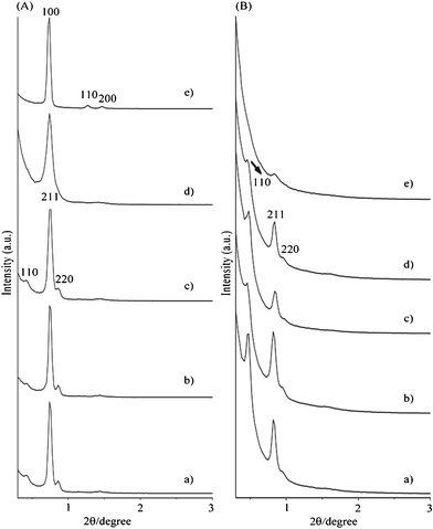
The powder XRD patterns of the as-synthesized sucrose/P123/silica nanocomposites with different molar ratios of sucrose/P123 less than 2.6 (Fig. 1A) exhibited three well-resolved diffraction peaks in the region of 2θ = 0.4°–1.0°, which can be indexed to the (110), (211), and (220) characteristic diffractions of the cubic I4132 mesostructure.9 Mesoporous silica materials with the cubic Ia![[3 with combining macron]](https://www.rsc.org/images/entities/char_0033_0304.gif) d mesostructure were formed when these as-synthesized composite samples were calcined for carbon removal (part A of Fig. S1, ESI†). It is noteworthy that a weak diffraction peak appeared at 2θ = 0.48° (Fig. 1A), corresponding to the position of the (110) reflection for the I4132 symmetry. This weak diffraction peak is not due to the Ia
d mesostructure were formed when these as-synthesized composite samples were calcined for carbon removal (part A of Fig. S1, ESI†). It is noteworthy that a weak diffraction peak appeared at 2θ = 0.48° (Fig. 1A), corresponding to the position of the (110) reflection for the I4132 symmetry. This weak diffraction peak is not due to the Ia![[3 with combining macron]](https://www.rsc.org/images/entities/char_0033_0304.gif) d symmetry because it is symmetrically forbidden for Ia
d symmetry because it is symmetrically forbidden for Ia![[3 with combining macron]](https://www.rsc.org/images/entities/char_0033_0304.gif) d.2 The observation of the (110) reflection for the I4132 symmetry is similar to the previous work reported by Zhao et al.9 When the sucrose/P123 molar ratio was increased to 10.2, a hexagonal p6mm mesophase with three well resolved (100), (110), and (200) diffraction peaks was observed (part e of Fig. 1A), indicating that a high amount of sucrose might induce a phase transformation from the cubic I4132 mesophase to the hexagonal p6mm mesophase.
d.2 The observation of the (110) reflection for the I4132 symmetry is similar to the previous work reported by Zhao et al.9 When the sucrose/P123 molar ratio was increased to 10.2, a hexagonal p6mm mesophase with three well resolved (100), (110), and (200) diffraction peaks was observed (part e of Fig. 1A), indicating that a high amount of sucrose might induce a phase transformation from the cubic I4132 mesophase to the hexagonal p6mm mesophase.
 | ||
| Fig. 1 Powder XRD patterns of (A) as-synthesized composites and (B) CCT-1 samples synthesized with different molar ratio of sucrose/P123: a) 0, b) 1.0, c) 1.8, d) 2.6 and e) 10.2. | ||
When the as-synthesized sucrose/P123/silica nanocomposites were carbonized at 600 °C followed by treatment with NaOH for silica removal, ordered mesoporous carbons CCT-1 can be obtained. Except for the sample prepared with a sucrose/P123 ratio of 10.2, all the CCT-1 samples showed three well-resolved diffraction peaks in the region of 2θ = 0.4°–1.0° (Fig. 1B), which can be indexed to the (211), and (220) characteristic diffractions of the cubic I4132 mesostructure. Therefore, direct transformation of the as-synthesized sucrose/P123/silica nanocomposites to the mesoporous carbons can be achieved without any change in the symmetry of the mesophase.
With increasing the carbonization temperature from 600 to 900 °C, the diffractions peaks of the CCT-1 sample were slightly shifted to higher 2θ values, reflecting a contraction of the unit cell size at higher carbonization temperature (part A of Fig. S1, ESI†) accompanied by the decrease in the intensity of the diffraction peaks, indicating that the cubic I4132 mesostructure was gradually degraded at a carbonization temperature of 900 °C.
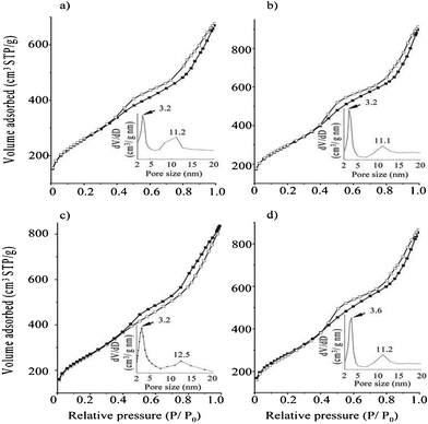
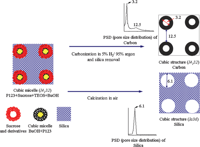
All of the CCT-1 samples exhibited typical type-IV isotherms with two obvious hysteresis loops at p/p0 of 0.5 and 0.9 (Fig. 2). Such isotherms indicate the existence of bimodal pore systems, each having a relatively narrow pore size distribution around 3.2–3.6 nm and 11.1–12.5 nm, respectively. The former may be contributed to the pores within the carbon tubes, which formed from the partial carbonization of the carbon particles derived from sucrose and its derivatives that interact with the PPO region and PEO region of P123 at the interface, while the latter resulted from the dissolution of the silica walls between two adjacent pores. After carbon removal, the CST-1 samples have a H1-type hysteresis loop of cylindrical pores (part B of Fig. S1, ESI†), which is closely agreed with those reported for KIT-6.12 This observation indicates that the addition of sucrose does not affect the mesostructure of the resultant mesoporous silica as long as the sucrose/P123 ratio is less than 2.6. The bicontinuous nature of the mesopore channels that were fully filled with sucrose leads to the Ia![[3 with combining macron]](https://www.rsc.org/images/entities/char_0033_0304.gif) d mesostructure with a pore size of around 6 nm after carbon removal (Fig. S1, ESI†). When the separating silica frameworks are removed by NaOH, the carbon networks surrounding the silica framework tend to shrink slightly to form smaller pores of 3.2–3.6 nm, accompanied by the large pores (around 12 nm) created by the replica of the Ia
d mesostructure with a pore size of around 6 nm after carbon removal (Fig. S1, ESI†). When the separating silica frameworks are removed by NaOH, the carbon networks surrounding the silica framework tend to shrink slightly to form smaller pores of 3.2–3.6 nm, accompanied by the large pores (around 12 nm) created by the replica of the Ia![[3 with combining macron]](https://www.rsc.org/images/entities/char_0033_0304.gif) d mesostructure. The relationship of the pore size distribution between CST-1 and CCT-1 is illustrated in Scheme 1.
d mesostructure. The relationship of the pore size distribution between CST-1 and CCT-1 is illustrated in Scheme 1.
 | ||
| Fig. 2 N2 adsorption-desorption isotherms and pore size distribution of CCT-1 carbon sample synthesized with various sucrose/P123 ratios of a) 0, b) 1.0, c) 1.8, and d) 2.6. | ||
 | ||
Scheme 1 Relationship of pore size distribution between CST-1 (Ia![[3 with combining macron]](https://www.rsc.org/images/entities/char_0033_0304.gif) d) and CCT-1 (I4132) mesostructures, taking the sample prepared with a sucrose/P123 ratio of 1.8 as an example. d) and CCT-1 (I4132) mesostructures, taking the sample prepared with a sucrose/P123 ratio of 1.8 as an example. | ||
The HRTEM images of the CCT-1 carbon materials shows a regular structure arrangement viewed along various directions (Fig. 3A), consistent with the previously reported literature.13 From the bright-dark contrast in the HRTEM image of the sample, the pore diameter are measured to be about 13.3 nm (part a of Fig. 3A) and 3.1–3.8 nm (parts b and c of Fig. 3A), respectively, which are close to the values of the pore diameter obtained from the nitrogen sorption measurements (Table 1). The center of the adjacent carbon pores is 21.0 nm apart, which is in good agreement with the value determined from XRD. The wall thickness of CCT-1 estimated from Fig. 3A is about 13.3 nm. The pores resulting from silica dissolution are thus appreciably thinner than the thickness (16.2 nm) of the silica walls of CST-1 (Table 1). This may be attributed to the contraction of the adjacent carbon tubes after silica dissolution and carbonization process. The resultant mesoporous carbon and silica materials show the same morphology of irregular rock-like crystals (Fig. 3B), implying a successful structure transfer between mesostructured carbon and silica.
![(A) TEM images of CCT-1 samples prepared with a sucrose/P123 ratio of 1.8, when viewed along a) [311], b) [110], and c) [001] directions. The insets are the corresponding fast Fourier transform (FFT) diffractograms. (B) SEM images for a) CST-1 and b, c) CCT-1 carbonized at 600 and 900 °C, respectively.](/image/article/2012/RA/c2ra00636g/c2ra00636g-f3.gif) | ||
| Fig. 3 (A) TEM images of CCT-1 samples prepared with a sucrose/P123 ratio of 1.8, when viewed along a) [311], b) [110], and c) [001] directions. The insets are the corresponding fast Fourier transform (FFT) diffractograms. (B) SEM images for a) CST-1 and b, c) CCT-1 carbonized at 600 and 900 °C, respectively. | ||
| Sucrose/P123 ratio | Lattice parameter a0 (nm)a | BET area (m2 g−1) | Mesopore volume (cm3 g−1) | Micropore volume (cm3 g−1) | Pore size (nm) | Wall thickness (nm) |
|---|---|---|---|---|---|---|
| a Lattice parameters a0 were calculated on the basis of the formula a0 = d211√6. b The numbers in parenthesis are micropore area calculated on the basis of t-plot method. c Sample was calcined in air at 550 °C for 6 h. d Sample was carbonized at 900 °C for 12 h, followed by complete silica removal. | ||||||
| 0 | 22.85 | 917 (67)b | 1.04 | 0.03 | 3.2/11.2 | 17.89 |
| 1 | 22.85 | 1066 (46) | 1.41 | 0.01 | 3.2/11.1 | 17.59 |
| 1.8 (CST-1)c | 22.35 | 562 (12) | 0.84 | 0.00 | 6.2 | 16.22 |
| 1.8 | 22.31 | 974 (16) | 1.29 | 0.00 | 3.2/12.5 | 16.99 |
| 1.8 (900 °C)d | 19.84 | 789 (143) | 0.83 | 0.07 | 3.7/9.3 | 15.07 |
| 2.6 | 22.31 | 1021 (32) | 1.34 | 0.01 | 3.6/11.1 | 17.11 |
TGA was conducted to determine the carbon and silica contents in the CCT-1 material under an air atmosphere. The small amount of residue (<2 wt.%) indicated that the removal of silica was nearly complete (Fig. S2A, ESI†). When the as-synthesized nanocomposite was thermally treated under an N2 atmosphere (Fig. S2B, ESI†), a more weight loss was observed as the sucrose/P123 ratio was increased from 0 to 1.8, suggesting that sucrose participates in the polymerization of P123.
In summary, we present, for the first time, a simple one-pot route for the synthesis of highly ordered mesoporous carbons and silicas with the cubic mesostructure via organic–inorganic self-assembly of tetraethoxysilane, triblock copolymer Pluronic P123 and sucrose under acidic conditions. By catalyzing silica/P123/sucrose composite with H2SO4, the mesoporous carbons with the cubic I4132 symmetry and bimodal pore structures were generated after carbonization and silica removal, while the mesoporous silicas with Ia![[3 with combining macron]](https://www.rsc.org/images/entities/char_0033_0304.gif) d symmetry were also obtainable by calcination of the aforementioned composite in air. In comparison to nanocasting, the present synthesis route has the advantage of being a simple and effective self-assembly method, and only involves the use of low-cost and environmentally friendly sucrose as an additional organic precursor.
d symmetry were also obtainable by calcination of the aforementioned composite in air. In comparison to nanocasting, the present synthesis route has the advantage of being a simple and effective self-assembly method, and only involves the use of low-cost and environmentally friendly sucrose as an additional organic precursor.
References
- (a) R. Liu, X. Wang, X. Zjao and P. Feng, Carbon, 2008, 46, 1664 CrossRef CAS; (b) M. Hartmann, A. Vinu and G. Chandrasekar, Chem. Mater., 2005, 17, 829 CrossRef CAS; (c) M. Hartmann, Chem. Mater., 2005, 17, 4577 CrossRef CAS.
- R. Ryoo, S. H. Joo and S. Jun, J. Phys. Chem. B, 1999, 103, 7743 CrossRef CAS.
- A. H. Lu and F. Schüth, Adv. Mater., 2006, 18, 1793 CrossRef CAS.
- I. Moriguchi, Y. Koga, R. Matsukura, Y. Teraoka and Y. M. Kodama, Chem. Commun., 2002, 1844 RSC.
- J. Lee, J. Kim, S. Yoon, S. M. Oh and T. Hyeon, Chem. Mater., 2004, 16, 3323 CrossRef CAS.
- C. D. Liang, K. L. Hong, G. A. Guiochon, J. W. Mays and S. Dai, Angew. Chem., Int. Ed., 2004, 43, 5785 CrossRef CAS.
- S. Tanaka, N. Nishiyama, Y. Egashira and K. Ueyama, Chem. Commun., 2005, 2125 RSC.
- F. Zhang, Y. Meng, Y. Yan, C. Yu, B. Tu and D. Y. Zhao, J. Am. Chem. Soc., 2005, 127, 13508 CrossRef CAS.
- (a) F. Zhang, Y. Meng, D. Gu, Y. Yan, Z. Chen, B. Tu and D. Y. Zhao, Chem. Mater., 2006, 18, 5279 CrossRef CAS; (b) Y. Meng, D. Gu, F. Zhang, Y. Shi, L. Cheng, D. Feng, Z. Wu, Z. Chen, Y. Wan, A. Stein and D. Y. Zhao, Chem. Mater., 2006, 18, 4447 CrossRef CAS.
- J. Kim, J. Lee and T. Hyeon, Carbon, 2004, 42, 2711 CrossRef CAS.
- L. Li, H. Song and X. Chen, Microporous Mesoporous Mater., 2006, 94, 9 CrossRef CAS.
- F. Kleitz, S. H. Choi and R. Ryoo, Chem. Commun., 2003, 2136 RSC.
- (a) K. Flodström, V. Alfredsson and N. Källrot, J. Am. Chem. Soc., 2003, 125, 4402 CrossRef; (b) V. Alfredsson and M. W. Anderson, Chem. Mater., 1996, 8, 1141 CrossRef CAS; (c) M. Kanaeda, T. Tusbakiyama, A. Carlsson, Y. Sakamoto, T. Ohsuna, O. Terasaki, S. H. Joo and R. Ryoo, J. Phys. Chem. B, 2002, 106, 1256 CrossRef.
Footnotes |
| † Electronic supplementary information (ESI) available: Text and scheme for synthesis procedures, XRD , N2 sorption, and TGA. See DOI: 10.1039/c2ra00636g |
| ‡ The financial support of this work by the National Science Council of Taiwan is gratefully acknowledged. |
| This journal is © The Royal Society of Chemistry 2012 |
