Tailored silica coated Ag nanoparticles for non-invasive surface enhanced Raman spectroscopy of biomolecular targets†
Arumugam
Sivanesan
,
Jacek
Kozuch
,
H. Khoa
Ly
,
Govindasamy
Kalaivani
,
Anna
Fischer
and
Inez M.
Weidinger
*
Technische Universität Berlin, Institut für Chemie, Sekr. PC 14, Straβe des 17. Juni 135, D-10623, Berlin, Germany. E-mail: i.weidinger@mailbox.tu-berlin.de; Fax: +49 3031421122; Tel: +49 3031422780
First published on 5th December 2011
Abstract
Silica coated Ag nanoparticles with defined surface plasmon resonances are used to selectively detect and analyze protein cofactors in solution and on interfaces via surface enhanced resonance Raman spectroscopy. The silica coating has a surprisingly small effect on optical amplification but minimizes unwanted interactions between the protein and the nanoparticle.
For rational design of biotechnological devices such as biosensors or biofuel cells, a profound understanding of the molecular processes between target molecules and their reaction partners is needed. Suitable in situ analytic techniques in this field should therefore be able to give structural information on the target molecules without interfering in the processes under investigation. These requirements are fulfilled by vibrational (IR and Raman) spectroscopic detection methods that have been used to study i.e. biological charge transfer reactions,1,2 or enzymatic catalysis.3–5 However, the complex vibrational patterns normally obtained from biological probes, make a selective detection method for the relevant processes by (i) local and (ii) target specific signal enhancement essential. The latter can be achieved by resonance Raman (RR) spectroscopy. Here the vibrational signal of a chromophore, i.e. a protein cofactor, is selectively enhanced by tuning the laser excitation line to the respective molecular electronic transition. Local enhancement on the other hand can be induced by addition of noble metal nanoparticles that are able to create surface plasmon resonances (SPRs) upon light excitation. This effect, which is especially advantageous for analysis of interfacial processes,6 has been largely exploited for surface enhanced Raman spectroscopy (SERS) where signal amplification of molecules in close vicinity to metal surfaces is achieved. A simultaneous local and target specific signal amplification can be obtained if the surface resonance of the nanoparticle is tuned to the molecular resonance of the target molecule. This two-fold resonance condition makes it in principle possible to follow target molecules and to analyze their interactions with other molecules or interfaces via surface enhanced resonance Raman spectroscopy (SERRS). However, intermolecular processes can easily be disturbed by the presence of the metal amplifiers; hence it has to be guaranteed that the nanoparticles, which are introduced artificially into the system, do not interfere with the molecular process under investigation. In this respect smart design of SERRS active, functional nanoparticles requires that the interactions with the target molecule are kept to a minimum, while efficient and selective enhancement is still provided. For resonance enhancement of chromophores that absorb in the blue and violet region the necessary surface enhancement can only be provided by silver nanoparticles (AgNPs). We have shown in our previous work that the SPR of AgNPs can be precisely tuned to match the molecular resonance of the model heme protein cytochrome c (Cyt c).7Protein denaturation was prevented by replacing the initially surface bound citrate ions with a self assembled monolayer of 11-mercaptoundecanoic acid (MUA). Cyt c was strongly bound to these Ag@MUA NPs, which resulted in a high Raman signal intensity but made it impossible to further study the interactions of the protein with other reaction partners. Silica coated metal particles have shown improve the stability of colloidal suspensions significantly8,9 and thus could be a good alternative to monolayer protected particles. Even though the optical properties of such metal@SiO2 particles have been studied in great detail10,11 not much is known about their interactions with biological probes. In this work we have therefore synthesized plasmon tuned, silica coated Ag@SiO2 NPs and studied their interaction with heme proteins. The NPs show excellent applicability in bioanalysis, as strong SERR signal enhancement of the heme cofactor is achieved, while binding between the protein and the particle is extremely weak.
For fabrication of Ag@SiO2 NPs with defined optical properties firstly small Ag@citrate nanoparticles (d = 12 nm, c ∼ 10 nM) were synthesized by reduction of AgNO3 with NaBH4 in the presence of citrate as described in reference 7. A portion of these particles were subsequently used as seeds for the synthesis of larger AgNPs by adding a growth solution that contained AgNO3 and ascorbic acid (AA) with defined concentration. Three more Ag@citrate NP batches were prepared this way by mixing 50 mL of the AgNPs seed solution with 0.2 (0.5, 1.0) mL of 1 mM AgNO3 and 0.2, 0.5 or 1.0 mL of 1 mM AA respectively. The resulting 4 Ag@citrate NPs batches were subsequently coated with a thin silica film following the procedures given in references 12 and 13. Briefly, a freshly prepared aqueous solution of 3-aminopropyltriethoxysilane (APTS 0.4 mL, 0.2%) was added to 25 mL of seeded AgNPs at pH 5.0. Defect free coating of the SiO2 layer was achieved by adding 2 mL of 2% sodium silicate solution. The pH was adjusted to 10.0 and the solution was stirred for 24 h. Finally, the silica coated Ag@SiO2 NPs were purified from other reagents by centrifugation and redispersed in water before being stored at 4 °C. The Ag@SiO2 NPs showed extremely high stability. Over the time scale of 6 months no aggregation was observed.
The particle shape was approximated by an ellipsoid exhibiting a longer (dlong) and a shorter (dshort) axis. We have shown previously that both diameters as well as their aspect ratio (dlong/dshort) are increased upon increasing the growth solution concentration.7 It is known that these two effects lead to a controlled red shift of the SPR position.14,15 A further red shift of 8–10 nm was introduced by coating with SiO2. A transmission electron micrograph (FEI Tecnai G² 20 S-TWIN, 200 kV) of Ag@SiO2 NPs with an SPR maximum at 413 nm is shown in Fig. 1 A. The shorter diameter dshort and the mean aspect ratio of the NPs were determined to be 18 ± 2 nm and 1.2 ± 0.3 respectively (Fig. S1†), which is in very good agreement with our previously published data.7 From Fig. 1 A, the successful SiO2 coating of the Ag@SiO2 NPs is visible. However, the SiO2 coating could be better evidenced by energy loss imaging (Zeiss LIBRA 200 FE, 200 kV), as shown in Fig. 1 B, where an average thickness of 4 ± 2 nm of the SiO2 layer could be determined (See also Fig. S1†). In Fig. 1 C UV-vis spectra for the 4 NP batches are shown. Depending on the growth solution concentration the SPR is shifted for each batch with respective maxima at 400, 408, 413 and 421 nm. The batches are in the following named according to their SPR maximum Ag400@SiO2, Ag408@SiO2, Ag413@SiO2 and Ag421@SiO2 NPs.
 | ||
| Fig. 1 (A) EFTEM zero loss image and (B) EFTEM energy loss image of Ag413@SiO2 NPs. (C) UV-vis spectrum of the Ag400@SiO2 (blue), Ag408@SiO2 (violet), Ag413@SiO2 (red) and Ag421@SiO2 (green) NP batches. (D) Cartoon of a Ag@SiO2 NP with Cyt c attached. The optical properties of Ag@SiO2 NPs were optimised for enhancement of heme cofactors. | ||
Cyt c is a small soluble redox protein that binds electrostatically to negatively charged surfaces via its lysine rich binding patch. It is therefore expected to interact also with the OH groups that exist at the SiO2 surface. Cyt c has seen detailed characterisation in the past with SERRS16,17 and is therefore also used in this work as a Raman marker and model protein. Cyt c was added to each Ag@SiO2 NP solution and the respective SERR spectra were measured in a rotating cuvette with the 413 nm excitation line of a Kr+ laser using a confocal Raman microscope (LabRam HR-800, Jobin Yvon). The vibrational spectrum of ferric Cyt c displays a prominent band (ν4) at Δν = 1370 cm−1, which is shown in Fig. 2 A and which was used in the following to determine the Raman enhancement factor (REF).
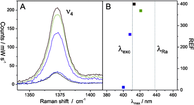 | ||
| Fig. 2 (A) RR (black) and SERR spectra (Ag400@SiO2 (blue), Ag408@SiO2 (purple), Ag413@SiO2 (red) and Ag421@SiO2 (green)) of Cyt c in the ν4 region. (B) Raman enhancement factors (REF) of the different Ag@SiO2 NP batches as a function of SPR maximum. The dashed lines indicate the wavelength of the excitation (λexc) and the Raman scattered (λRa,ν4) line. | ||
The REF can be calculated from measured RR and SERR intensities according to:
 | (1) |
For cRR the Cyt c concentration in solution c0 = 20 μM was taken. The factor ISERRS/IRR = 6 was determined from the difference in Raman intensity with and without NPs present in solution. k is a shielding factor determined in previous work to be 0.25.18 The concentration of surface bound Cyt c (cSERRS) in the saturation limit was measured to be 1.2 μM for the Ag413@SiO2 NP batch following a procedure described in reference 7 (Fig. S2†). This corresponds to a Cyt c surface concentration of 9.5 pM cm−2 or 60% of the geometrical possible coverage.
If we assume that cSERRS is equal for all Ag@SiO2 NPs, REF can be derived for all NP batches from eqn (1) and is plotted in Fig. 2 B as a function of the respective SPR maximum.
REF can be seen as the product of the wavelength dependent electric field enhancement intensity EF(λ) at the exciting (λexc) and Raman scattered (λRa) wavelengths:
| REF = EF(λexc)EF(λRa) | (2) |
The measured values for REF correspond to enhancement factors at a distance from the Ag surface that is controlled by the thickness of the SiO2 coating. For spherical NPs in a homogeneous medium the distance dependence of REF is given by:20
 | (3) |
It should be noted that the SPR could also be tuned to 413 nm by using smaller Ag NPs and thicker SiO2 coatings (see Fig. S1 B and S3†) but in these cases REF was distinctly smaller. For example, REF of Ag413@SiO2 NPs with dshort = 17 ± 5 nm and d(SiO2) = 6 ± 2 nm was determined to be ca. 100. For Ag413@SiO2 NPs with 15 nm SiO2 coatings no SERR enhancement could be observed any more (Fig. S3†).
For applications of Ag@SiO2 NPs as non-invasive amplifiers it is required that binding of target proteins to the NPs is weak enough not to interfere with the processes under investigation. The binding properties of Cyt c to the Ag413@SiO2 particles were therefore tested by UV-vis spectroscopy upon adding and removing the NPs in a Cyt c containing solution as shown in Fig. 3. The data were compared with similar measurements using Ag413@MUA NPs from ref. 7.
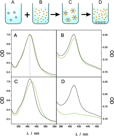 | ||
| Fig. 3 Black lines: Uv-vis spectra of (A) Ag413@SiO2 NPs in solution, (B) Cyt c, (C) Ag413@SiO2 NPs together with Cyt c and (D) after centrifugation of the NPs. The green lines correspond to identical measurements using Ag413@MUA NPs (data taken from ref. 7). | ||
In Fig. 3 A and B the UV-vis spectra of the NPs (Ag413@SiO2 (black) and Ag413@MUA (green)) and Cyt c in separate solutions are shown respectively. In both cases the characteristic absorption peaks around 413 nm for the NPs and 410 nm for ferric Cyt c can be seen. If both, Cyt c and NP, solutions are put together a red shift in the SPR for Ag413@MUA NPs is observed but not for Ag413@SiO2 NPs (Fig. 3 C). In the case of Ag413@MUA the SPR shift is most likely caused by a change in the local dielectric environment of the particle, indicating the formation of a strong Ag@MUA-Cyt c complex. The UV-vis spectrum of Ag@SiO2 NPs with Cyt c on the other hand is a superposition of the two isolated systems shown in Fig. 3 A and B, leading to the conclusion that no strong interacting NP–protein complex is formed. This assumption is further confirmed by Fig. 3 D, which shows the UV-vis spectra of the solutions after centrifugation of the NPs. In the case of Ag413@SiO2 NPs Cyt c remained in solution, while it was centrifuged away with the NPs in the case of Ag413@MUA NPs. Based on these observations we conclude that the interaction of Ag413@SiO2 NPs with Cyt c is much weaker than for Ag413@MUA NPs.
The biocompatibility of the Ag@SiO2 NPs was tested by comparing the SERR spectrum of Cyt c with its RR spectrum in solution (Fig. 4 A and B). The high similarity between the two spectra indicates that no alteration of the heme pocket structure occurred upon surface attachment. This observation can also be seen as an additional proof for the weak binding between Cyt c and the NPs. Surprisingly strong alterations in the spectral pattern were observed when the same SiO2 coating procedure was applied to rough Ag electrodes. In this case a significant contribution from a non-native high spin species24 was observed, indicated by an additional band at 1490 cm−1 (Fig. 4 C). This denaturation effect has already been reported in a previous work using a slightly different SiO2 coating procedure25 and is attributed to the fact that on rough metal surfaces a non-complete SiO2 layer is formed and thus spectral contributions of Cyt c bound directly to the Ag surface are observed. Since these proteins are very close to the Ag surface even a small amount of this fraction can dominate the SERR spectrum.
 | ||
| Fig. 4 (A) RR spectrum of Cyt c in solution. (B, C) SERR spectra of Cyt c bound to Ag413@SiO2 NPs and on rough Ag@SiO2 electrodes. (D) SERR spectrum of YCyt c covalently bound to flat Au electrodes after Ag@SiO2 NP attachment. | ||
The Ag@SiO2 NPs were finally used to enhance the signal of proteins bound to plasmon inactive surfaces. As a reference system yeast cytochrome c (YCyt c) immobilised on a flat Au surface was chosen. Covalent binding of YCyt c to the bare Au electrode was achieved via its single surface cysteine Cys102 as follows: a cleaned Au electrode was immersed into 35 μM aqueous solution of YCyt c for 1 h followed by immersion into 2 M KCl solution for 20 min to remove the electrostatically bound proteins and rinsing with water.
Subsequently performed SERR experiments of the Au-YCytcelectrode did not give any Raman signal. After adding 20 μL of Ag@SiO2 NP solution the signal increased significantly with time, which we attribute to a slow deposition of the NPs on the Au surface. After approximately 1 h a stable high quality Raman spectrum could be obtained (Fig. 4 D). The signal exclusively arises from proteins bound to the Au surface as the weak attraction of the NPs is not able to break the strong thiol bond between YCyt c and Au. The spectrum of the covalently bound YCyt c showed a significant contribution from the non-native high spin species, which is in agreement with previous SERR measurements of YCyt c bound viaCys102 to Au–Ag hybrid electrodes.26
In summary we have shown that Ag@SiO2 NPs with tunable optical properties are able to selectively enhance protein chromophores while, due to the very weak interaction with the target molecule, the properties of the protein are not affected. In comparison to monolayer protected Ag@MUA NPs the silica coating leads to higher SERR intensity upon a much lower protein binding affinity. These NPs are therefore very promising candidates as non-invasive optical amplifiers for the spectroscopic analysis of biomolecular processes. Preliminary measurements also show that these NPs can be used for amplification of target molecules bound to plasmon inactive surfaces.
Acknowledgements
The authors would like to thank Peter Hildebrandt for helpful discussions. Also the ZELMI (TU Berlin) and the Helmholtz-Zentrum Berlin are gratefully acknowledged for access to the TEM facilities and particularly Soeren Selve and Markus Wollgarten for helpful discussions. Financial support from the Fonds der Chemie (IW), the Alfried Krupp Wissenschaftskolleg, Greifswald (AS) and the DFG (Unicat) is gratefully acknowledged.References
- H. K. Ly, M. Sezer, N. Wisitruangsakul, J. J. Feng, A. Kranich, D. Millo, I. M. Weidinger, I. Zebger, D. H. Murgida and P. Hildebrandt, FEBS J., 2011, 278, 1382 CrossRef CAS.
- C. Kotting and K. Gerwert, ChemPhysChem, 2005, 6, 881 CrossRef.
- D. Millo, M. E. Pandelia, W. Lubitz, P. Hildebrandt and I. Zebger, Angew. Chem., Int. Ed., 2011, 50, 2632 CrossRef CAS.
- T. Ogura and T. Kitagawa, Biochim. Biophys. Acta, Bioenerg., 2004, 1655, 290 Search PubMed.
- R. M. Nyquist, D. Heitbrink, C. Bolwien, R. B. Gennis and J. Heberle, Proc. Natl. Acad. Sci. U. S. A., 2003, 100, 8715 CrossRef CAS.
- J. F. Li, Y. F. Huang, Y. Ding, Z. L. Yang, S. B. Li, X. S. Zhou, F. R. Fan, W. Zhang, Z. Y. Zhou, D. Y. Wu, B. Ren, Z. L. Wang and Z. Q. Tian, Nature, 2010, 464, 392 CrossRef CAS.
- A. Sivanesan, H. K. Ly, J. Kozuch, M. Sezer, U. Kuhlmann, A. Fischer and I. M. Weidinger, Chem. Commun., 2011, 47, 3553 RSC.
- R. A. Caruso and M. Antonietti, Chem. Mater., 2001, 13, 3272 CrossRef CAS.
- P. Mulvaney, L. M. Liz-Marzan, M. Giersig and T. Ung, J. Mater. Chem., 2000, 10, 1259 RSC.
- V. Salgueirino-Maceira, F. Caruso and L. M. Liz-Marzan, J. Phys. Chem. B, 2003, 107, 10990 CrossRef CAS.
- T. Ung, L. M. Liz-Marzan and P. Mulvaney, J. Phys. Chem. B, 2001, 105, 3441 CrossRef CAS.
- L. M. LizMarzan, M. Giersig and P. Mulvaney, Langmuir, 1996, 12, 4329 CrossRef CAS.
- T. Ung, L. M. Liz-Marzan and P. Mulvaney, Langmuir, 1998, 14, 3740 CrossRef CAS.
- S. Link and M. A. El-Sayed, J. Phys. Chem. B, 1999, 103, 8410 CrossRef CAS.
- K. L. Kelly, E. Coronado, L. L. Zhao and G. C. Schatz, J. Phys. Chem. B, 2003, 107, 668 CrossRef CAS.
- D. H. Murgida and P. Hildebrandt, Acc. Chem. Res., 2004, 37, 854 CrossRef CAS.
- J. J. Feng, D. H. Murgida, U. Kuhlmann, T. Utesch, M. A. Mroginski, P. Hildebrandt and I. M. Weidinger, J. Phys. Chem. B, 2008, 112, 15202 CrossRef CAS.
- P. Hildebrandt and M. Stockburger, J. Phys. Chem., 1986, 90, 6017 CrossRef CAS.
- A. D. McFarland, M. A. Young, J. A. Dieringer and R. P. Van Duyne, J. Phys. Chem. B, 2005, 109, 11279 CrossRef CAS.
- F. Siebert and P. Hildebrandt, Vibrational Spectroscopy in Life Science, Wiley-VCH, Weinheim, 2008 Search PubMed.
- E. J. Zeman and G. C. Schatz, J. Phys. Chem., 1987, 91, 634 CrossRef CAS.
- J. J. Feng, U. Gernert, M. Sezer, U. Kuhlmann, D. H. Murgida, C. David, M. Richter, A. Knorr, P. Hildebrandt and I. M. Weidinger, Nano Lett., 2009, 9, 298 CrossRef CAS.
- C. David, M. Richter, A. Knorr, I. M. Weidinger and P. Hildebrandt, J. Chem. Phys., 2010, 132, 024712 CrossRef.
- S. Oellerich, H. Wackerbarth and P. Hildebrandt, J. Phys. Chem. B, 2002, 106, 6566 CrossRef CAS.
- J. J. Feng, U. Gernert, P. Hildebrandt and I. M. Weidinger, Adv. Funct. Mater., 2010, 20, 1954 Search PubMed.
- M. Sezer, J. J. Feng, H. K. Ly, Y. F. Shen, T. Nakanishi, U. Kuhlmann, P. Hildebrandt, H. Mohwald and I. M. Weidinger, Phys. Chem. Chem. Phys., 2010, 12, 9822 RSC.
Footnote |
| † Electronic supplementary information (ESI) available: Further characteristics of Ag@SiO2 NPs from TEM measurements. SERR intensities of Cyt c as a function of concentration. See DOI: 10.1039/c1ra00781e |
| This journal is © The Royal Society of Chemistry 2012 |