 Open Access Article
Creative Commons Attribution 3.0 Unported Licence
Chitin nanofibers: preparations, modifications, and applications
Shinsuke
Ifuku
* and
Hiroyuki
Saimoto
Department of Chemistry and Biotechnology, Tottori University, Tottori 680-8552, Japan. E-mail: sifuku@chem.tottori-u.ac.jp; Fax: +81 857 31 5592; Tel: +81 857 31 5592
First published on 26th March 2012
Abstract
Chitin nanofibers are prepared from the exoskeletons of crabs and prawns by a simple mechanical treatment after the removal of proteins and minerals. The obtained nanofibers have fine nanofiber networks with a uniform width of approximately 10–20 nm and a high aspect ratio. The method used for chitin-nanofiber isolation is also successfully applied to the cell walls of mushrooms. They form a complex with glucans on the fiber surface. A grinder, a Star Burst atomization system, and a high speed blender are all used in the mechanical treatment to convert chitin to nanofibers. Mechanical treatment under acidic conditions is the key to facilitate fibrillation. At pH 3–4, the cationization of amino groups on the fiber surface assists nano-fibrillation by electrostatic repulsive force. By applying this finding, we also prepared chitin nanofibers from dry chitin powder. Chitin nanofibers are acetylated to modify their surfaces. The acetyl DS can be controlled from 1 to 3 by changing the reaction time. An acetyl group is introduced heterogeneously from the surface to the core. Nanofiber morphology is maintained even in the case of high acetyl DS. Optically transparent chitin nanofiber composites are prepared with 11 different types of acrylic resins. Due to the nano-sized structure, all of the composites are highly transparent. Chitin nanofibers significantly increase the Young's moduli and the tensile strengths and decrease the thermal expansion of all acrylic resins due to the reinforcement effect of chitin nanofibers. Chitin nanofibers show chiral separation ability. The chitin nanofiber membrane transports the D-isomer of glutamic acid, phenylalanine, and lysine from the corresponding racemic amino acid mixtures faster than the corresponding L-isomer. The chitin nanofibers improve clinical symptoms and suppress ulcerative colitis in a DSS-induced mouse model of acute ulcerative colitis. Moreover, chitin nanofibers suppress myeloperoxidase activation in the colon and decrease serum interleukin-6 concentrations.
 Shinsuke Ifuku | Shinsuke Ifuku received his PhD from Kyoto University in 2005 under the supervision of Prof. Fumiaki Nakatsubo for regioselective modifications of cellulose and the applications of Langmuir–Blodgett films. In 2005 and 2006, he joined Prof. Hiroyuki Yano's group and worked on modifications and applications of cellulose nanofibers as a JSPS postdoctoral fellow. He spent 2007 at the Faculty of Forestry, The University of British Columbia, Canada, working with Prof. John F. Kadla as a postdoc to study graft copolymerization of cellulose through atom transfer radical polymerization. In 2008, he joined Prof. Hiroyuki Saimoto's group as a Junior Associate Professor, and started studying the preparations and applications of chitin nanofibers. He was promoted to Associate Professor in 2011. |
 Hiroyuki Saimoto | Hiroyuki Saimoto received his PhD from Kyoto University in 1983 under the supervision of Prof. Hitoshi Nozaki for new methods for synthesizing five-membered ring compounds and their applications. While a graduate student, he spent 1982 with Prof. Leon Ghosez at the Universitecatholique de Louvain, Belgium. In 1983, he joined Dr Tamejiro Hiyama's group in Sagami Chemical Research Center as a postdoc. In 1986, he joined Prof. Yoshihiro Shigemasa's group as an Associate Professor. He spent 1992 at the Scripps Research Institute, California, USA, working with Prof. K. C. Nicolaou. He was promoted to full Professor in 2006. Since 1986 he has worked on synthesis, modification, and functionalization of naturally occurring compounds and utilization of biomass. |
1. Introduction
Nanofibers are generally defined as fibers with diameters less than 100 nanometres and an aspect ratio of more than 100.1,2 Since nanofibers have an extremely high surface to volume ratio,3 and form a highly porous mesh,4 their properties are different from those of micro-sized fibers. Therefore, preparation of nanofibers is an important subject because of their unique dimensional, optical, mechanical, and other characteristics. These features allow many promising properties for advanced materials. Nanofibers are generally artificially prepared by an electro-spinning process, which produces fibers from a polymer solution using interactions between fluid dynamics, electrically charged surfaces and electrically charged liquids.5,6 However, the environmental load of the process is high. Recently, there has been growing interest in producing nanofibers from biopolymers, since they have environmentally friendly functions such as biodegradability, biocompatibility, renewability, and sustainability. Nature produces a variety of nanofibers, such as collagen triple helix fibers, fibroin fibrils, keratin fibrils, and so on. These nanofibers form a complex hierarchical organization. This suggests the possibility that nanofibers are extracted from the biomass-derived organizations by downsizing their structures. Although the electro-spinning process is a “bottom-up” approach because it bundles molecules into nanofibers, the extraction of nanofibers from biomass is considered to be a “top-down” approach.Among the variety of bio-based products, cellulose is the most abundant biopolymer, existing mainly in wood cell walls (Fig. 1). Wood has a unique multilayered hierarchical structure. The cellulose nanofibers, called microfibrils, are highly crystalline structures with 3–4 nm thickness, which consist of 30–40 cellulose molecules. The bundles of microfibrils are embedded in matrix components such as hemicellulose and lignin to form a wood cell wall. Due to their extended crystalline structure, the microfibrils have excellent physical properties. Their Young's modulus is 138 GPa,7 their tensile strength is at least 2 GPa,8 and their thermal-expansion coefficient in the axial direction is as small as 0.1 × 10⁻⁶ K−1.9 Because of the excellent mechanical properties and complicated structure of wood cell walls, wood itself is stiff and sufficiently tough to support the huge body of a tree. Since cellulose nanofibers have potential as high performance materials, a number of downsizing methods have been employed to obtain cellulose nanofibers. Mechanical treatments have been mainly employed for cellulose nanofiber preparation using high pressure homogenizers,10 grinders,11,12 cryocrushing,13,14 ultrasonic disintegrators,15 or enzymatic methods.16 However, due to the complex structure of the cell walls and the strong interfibrillar hydrogen bonding, it has been difficult to obtain completely disintegrated cellulose nanofibers without high disintegration load and damage to the cellulose.
Abe et al. isolated cellulose nanofiber bundles with approximately 15 nm width from wood by a simple process.17 Since cellulose nanofibers are embedded in the matrix phase, which acts as a glue between nanofibers, they can be isolated by first removing the matrix components and subsequently downsizing to nanofibers by a very simple grinding treatment. This method has been applied for rice straw, potato tuber pulp, and parenchymal cells of bamboo and fruits to isolate cellulose nanofibers.18–20 Isogai et al. converted wood cellulose to nanofibers of 3–4 nm width and high aspect ratio by 2,2,6,6-tetramethylpiperidine-1-oxyl radical (TEMPO)-mediated oxidation. TEMPO-oxidation forms carboxylate groups on the cellulose surface. Electrostatic repulsion arises due to anionic charges at the cellulose surface and causes complete disintegration into nanofibers.21–24
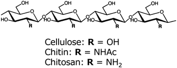
Chitin and chitosan are known to be cellulose analogues with a (1,4)-β-N-acetyl glycosaminoglycan-repeating structure and a deacetylated derivative, respectively (Fig. 1). After cellulose, chitin is the second most abundant biopolymer, occurring mainly in the exoskeletons of shellfish and insects and the cell walls of mushrooms. It is biosynthesized at a rate of 1010 to 1011 tons per year.25 Although chitin is a semicrystalline biopolymer with nano-sized fibrillar morphology and excellent material properties, most chitin is thrown away as industrial waste. Therefore, it is important to make effective use of chitin as an environmentally friendly green material. Because of its linear structure with two hydroxyl groups and an acetamide group, chitin is highly crystalline with strong hydrogen bonding having high binding energy, and is arranged as nano-size chitin nanofibers in an antiparallel fashion. The nanofibers are about 2–5 nm in diameter and about 300 nm in length embedded in a protein matrix.26–29 Since crab and prawn shells have a hierarchical structure made up of the nanofibers, we consider that the cellulose nanofiber isolation method is applicable to several biomasses consisting of chitin nanofibers. However, there have been few reports on the preparation of chitin nanofibers by a top-down approach, compared with the numerous reports on the bottom-up preparation of cellulose nanofibers. Chitinnanocrystals have been prepared by acidolysis of amorphous domains of semicrystalline chitin.30 The chitinnanocrystals can be used in reinforcing polymer nanocomposites. However, the crystals with low aspect ratio do not represent the natural fibril form of chitin produced by crab and prawn. We have developed a simple method for the preparation of chitin nanofibers. In this feature article, we review the available procedures for preparing chitin nanofibers, and the fundamental characteristics and potential applications of the nanofibers produced by these methods.
2. Preparation of chitin nanofibers
Crab shells have a hierarchical organization with various structural levels, as shown in Fig. 2. That is, chitin molecules form chitin nanofibers with an extended crystalline structure, which is wrapped in protein layers. The next level in the scale consists of the bundle of chitin nanofibers with thicker diameter. The next level is the planar woven and branched network of bundled nanofibers. The network is embedded in a variety of proteins and calcium carbonate. These woven network planes form a twisted plywood pattern with helicoidal stacking sequences, or a so-called “Bouligand structure.” Chitin nanofibers have been extracted from crab shells having such complicated hierarchical structures.31 To extract chitin nanofibers, the sample was purified by a series of chemical treatments and then subjected to mechanical treatment, according to the flow chart shown in Fig. 3. The matrix components, proteins and minerals were removed from the crab shells by aqueous NaOH and HCl treatments, respectively.32,33 The crab shell surface after removal of the matrices was observed by SEM (Fig. 4). Although the shape of the crab shell was maintained, we could see that the crab shell was made up of an aggregation of chitin nanofibers. A grinder (Masuko Sangyo Co., Ltd.) was used to disintegrate the aggregates of chitin nanofibers. A specially designed pair of grinding stones was used to break down the sample. Thus, the purified chitin with 1 wt.% concentration in water was passed through a grinder. After grinder treatment, the chitin slurry formed a gel. This suggests that disintegration was accomplished because a sample with high surface-to-volume ratio was dispersed well in water. The woven network structure shown in Fig. 4 looks completely disintegrated. The chitin consisted of highly uniform nanofibers with a width of 10–20 nm, high aspect ratio, and uniform structure (Fig. 5). In most cases, the sample must be kept wet through a series of processes. The drying process causes strong interfibrillar hydrogen bonding on the chitin surface, which makes disintegration difficult. Therefore, a method without drying at any point is important for the preparation of bio-nanofibers, including cellulose.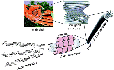 | ||
| Fig. 2 Schematic presentation of the exoskeleton structure of crab shells. | ||
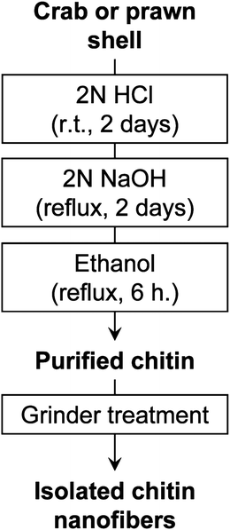 | ||
| Fig. 3 Preparation procedure of chitin nanofibers from crab and prawn shells. | ||
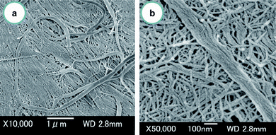 | ||
| Fig. 4 FE-SEM micrographs of the crab shell surface after removal of the matrix. The lengths of the scale bars are (a) 1000 nm and (b) 100 nm. Reprinted with permission from ref. 31. Copyright 2009, American Chemical Society. | ||
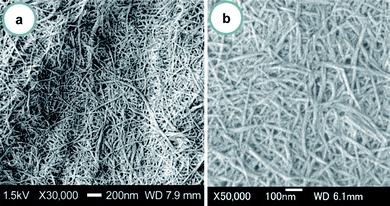 | ||
| Fig. 5 FE-SEM micrographs of chitin nanofibers from crab shells after one pass through the grinder. The lengths of the scale bars are (a) 200 nm and (b) 100 nm. Reprinted with permission from ref. 31. Copyright 2009, American Chemical Society. | ||
The degree of substitution (DS) of the acetamide group as calculated by elemental analysis data was 0.96, indicating that significant deacetylation did not occur after the series of treatments. The FT-IR spectrum of prepared chitin nanofibers was in excellent agreement with that of pure chitin, indicating that the matrix components were well-removed by conventional processing.34 The X-ray diffraction profile of chitin nanofibers shows antiparallel crystal patterns typical of α-chitin.35 These results indicate that the chitin nanofibers still had their original molecular and crystalline structures, even after removal of the matrix and the subsequent grinder treatment.
The preparation method for chitin nanofibers is applicable to a variety of prawn shells.36 Three types of prawn shells, Penaeusmonodon (black tiger prawn), Marsupenaeus japonicus (Japanese tiger prawn), and Pandalus eous Makarov (Alaskan pink shrimp), were purified to isolate chitinpolysaccharides by conventional chemical treatments. These prawns are important food sources and are widely cultured throughout the world. However, their shells are often thrown away without effective utilization. The purified wet chitin was treated with a grinder for disintegration. The obtained chitin slurry was also viscous after one-pass treatment even with 1 wt.% concentration. A uniform structure of the chitin nanofibers was observed over an extensive area. The fiber structure obtained from the three types of prawns with a thickness of 10–20 nm was similar to that of nanofibers obtained from crab shells (Fig. 6). The advantage of obtaining the chitin nanofibers from prawn shells is that the prawn-derived chitin can be fibrillated into nanofibers with low mechanical load, for the following reason. The exoskeletons of crabs and prawns are made up of two parts, the exocuticle and endocuticle. Although the exocuticle has a fine twisted plywood structure, the endocuticle has a thicker and coarser structure. Crab shells are mainly made up of the coarser endocuticle.37 On the other hand, prawn shells with a semitransparent soft shell are made up primarily of a finer exocuticle (Fig. 7).38 Due to this important morphological difference, it is easier to fibrillate chitin from prawn shells than from crab shells.
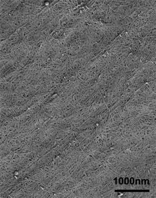 | ||
| Fig. 6 FE-SEM micrograph of chitin nanofibers from black tiger prawn shells. The length of the scale bar is 1000 nm. Reproduced with permission from ref. 36. Copyright 2011, Elsevier. | ||
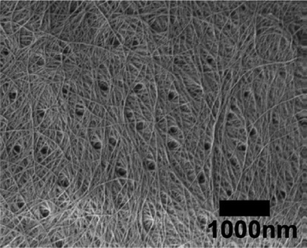 | ||
| Fig. 7 FE-SEM micrograph of the surface of the black tiger prawn shell after removing the matrices. The length of the scale bar is 1000 nm. Reproduced with permission from ref. 36. Copyright 2011, Elsevier. | ||
The cell walls of mushrooms also consist of a chitin nanofiber network which is embedded in the matrices mainly of glucans.39,40 Edible mushrooms are a good source of dietary fiber, which is important for the bulking or thickening of foods, film forming agents, and stabilizers.41,42 Thus, we applied the above-described method of isolating chitin nanofibers to the fruiting bodies of mushrooms.43 Since the organizational structure and ingredients of mushroom cell walls are different from those of crab and prawn shells, it was necessary to arrange the procedure for preparing the chitin nanofibers. Five different species of mushrooms, Pleuotus eryngii (king trumpet mushroom), Agaricus bisporus (common mushroom), Lentinula edodes (shiitake), Grifola frondosa (maitake), and Hypsizygus marmoreus (buna-shimeji), which are widely used for human consumption, were selected for the isolation of chitin nanofibers. The chitin nanofibers were obtained from these mushrooms by a series of chemical treatments with NaOH, HCl, and NaClO2 to remove the associated components: proteins, pigments, glucans, and minerals.44 The extracted sample was passed through a grinder with acetic acid to facilitate nano-fibrillation. The obtained chitins had uniform and very thin nanofibers (Fig. 8). The nanofibers prepared from five different mushrooms were similar to those from crab and prawn shells. The main characteristic of the chitin nanofibers from mushrooms was that they formed a complex with several glucans on their surface. This is because it was difficult to completely remove the glucans from chitin by chemical treatment, since both glucan and chitin are categorized as carbohydrate polymers. The content ratio of glucan varied widely with the type of mushrooms. The width of nanofibers varied from 20 to 28 nm depending on the glucan content. The average diameter of the nanofibers was estimated counting 30 nanofibers manually. Although the X-ray diffraction patterns of these chitin nanofibers showed the typical crystal patterns of α-chitin, the relative crystalline indices of the chitin nanofibers decreased from 80.0% to 47.6% with the increase in the amount of amorphous glucan. As a result of these analyses, mushroom nanofibers have been added to the list of useful dietary nanofibers along with the nanofibers derived from crab and prawn shells. Moreover, the dietary nano-sized fibers obtained from cultivable and edible mushrooms will have a wide range of applications, from use as novel functional food ingredients to medical applications.
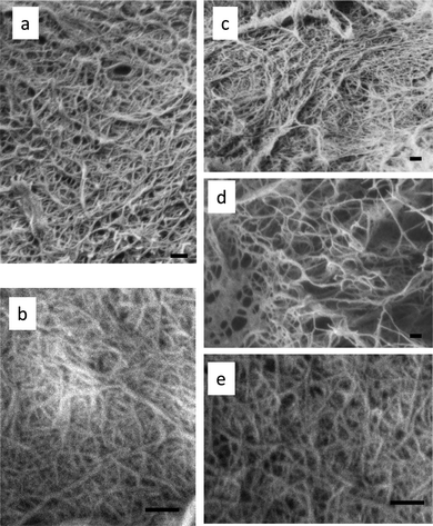 | ||
| Fig. 8 FE-SEM micrographs of chitin nanofibers prepared from (a) Pleuotus eryngii, (b) Agaricus bisporus, (c) Lentinula edodes, (d) Grifola frondosa, and (e) Hypsizygus marmoreus. The scale bars are 200 nm in length. | ||
Fan et al. reported the production of chitinnanocrystals by TEMPO-mediated oxidation of α-chitin. Carboxylate groups formed on the chitin crystalline surface caused electrostatic repulsion, resulting in the formation of individual chitinnanocrystals by a gentle mechanical disintegration treatment.45 The average nanocrystal length and width were 340 nm and 8 nm, respectively. Moreover, they prepared chitin nanofibers of 3–4 nm length from squid pen β-chitin by a simple procedure without the need for a chemical modification such as TEMPO-mediated oxidation.46 The use of squid pen β-chitin as the starting material and mechanical treatment in water at pH 3–4 were the key factors for the preparation of chitin nanofibers. The C2 amino groups on the crystalline surfaces were cationized under acidic conditions. This promoted facile fibrillation and stable dispersions in water by electrostatic repulsions between the nanofibers. In addition, squid pen β-chitin has a lower crystalline index and lower intermolecular forces than the nanofibers from α-chitin. These factors allowed for simple individualization.
As described above, the drying process of chitin induces strong interfibrillar hydrogen bondings. This makes it difficult to fibrillate chitin to nanofibers. For this reason, the chitin must be kept wet after removal of the matrix in order to prepare the nanofibers. However, this is regarded as a major disadvantage for the commercialization of chitin nanofibers. We found that the above-described electrostatic repulsion force of aminocations on the chitin surface can break the hydrogen bonds.47 By exploiting this force, chitin nanofibers can be obtained from dried chitin aggregates. Fig. 9 shows an SEM image of the dried chitin prepared from crab shells by a series of chemical treatments followed by drying. The chitin was made up of regularly structured bundles of nanofibers. The dried chitin was dispersed in water with a concentration of 1 wt.% and passed through a grinder with and without acetic acid. In the case of the grinding without acetic acid, the dried chitin was not fibrillated at all and thick bundles of chitin nanofibers remained (Fig. 9b). This was due to the strong hydrogen bonds on the chitin surface, which made it difficult to fibrillate bundles of chitin nanofibers. On the other hand, with acetic acid, the chitin slurry was successfully fibrillated by one-pass grinder treatment (Fig. 9c and d). The chitin sample had a very fine nanofiber network with a uniform width of 10–20 nm. The structure seemed very similar to that of nanofibers prepared with a conventional process in which the chitin was never dry. The pronounced difference in morphology between the preparation with and without acetic acid was clearly due to the electrostatic repulsion effect. The repulsive force caused by the cationization of amino groups facilitated fibrillation into nanofibers. In general, the DS of the amino group of natural chitin is very low (less than 5%). However, the repulsive force was sufficient to break the strong hydrogen bonds on the chitin surface. In addition to acetic acid, several other organic acids can be selected for facile nano-fibrillation, including ascorbic acid, citric acid, and lactic acid, depending on the proposed application. This use of acid-induced electrostatic repulsion yields chitin that is dry, light, low in volume, and nonperishable, and thus constitutes a significant advantage for commercial applications in terms of providing a stable supply of chitin that is easy to store and transport.
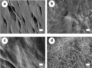 | ||
| Fig. 9 FE-SEM micrographs of (a) a crab shell after removing matrix components, and chitin fibers after one pass through the grinder treated (b) without and (c and d) with acetic acid. The lengths of the scale bars are (a–c) 300 nm and (d) 100 nm. Reproduced with permission from ref. 47. Copyright 2011, Elsevier. | ||
The preparation method is of course applicable for commercially available dry chitin powder. Since commercial chitin is also made up of aggregates of nanofibers, the aggregates can clearly be fibrillated into homogeneous nanofibers at pH 3–4. Production of chitin nanofibers from commercial chitin is advantageous for use in nanofiber research and development, because a large amount of chitin can be obtained within a few hours by a simple fibrillation under acidic conditions without any purification processes, which require at least 5 days. However, this advantage cannot be utilized for cellulose, since it does not have ionic functional groups to cause electrostatic repulsions.
By exploiting the repulsive force, chitin nanofibers can also be obtained using a simple high-speed blender.48 After 10 min of blending at a rotation speed of 37![[thin space (1/6-em)]](https://www.rsc.org/images/entities/char_2009.gif) 000 rpm under an acidic condition, the purified chitin from crab shells was disintegrated into nanofibers having a uniform width of 20–30 nm. Moreover, chitin could be disintegrated into nanofibers by using a unique Star Burst instrument that employs a high pressure water jet.49,50 In the preparation using the Star Burst system, the chitin slurry is compressed, ejected at a high pressure of 245 MPa from a nozzle, and collided with a ceramic ball in a chamber for the disintegration. The chitin became thinner as the number of Star Burst passes increased. The Star Burst system did not damage the chitin nanofibers and did not reduce their crystallinity. The Star Burst system has advantages in quality stability, high-volume production, and low contamination.
000 rpm under an acidic condition, the purified chitin from crab shells was disintegrated into nanofibers having a uniform width of 20–30 nm. Moreover, chitin could be disintegrated into nanofibers by using a unique Star Burst instrument that employs a high pressure water jet.49,50 In the preparation using the Star Burst system, the chitin slurry is compressed, ejected at a high pressure of 245 MPa from a nozzle, and collided with a ceramic ball in a chamber for the disintegration. The chitin became thinner as the number of Star Burst passes increased. The Star Burst system did not damage the chitin nanofibers and did not reduce their crystallinity. The Star Burst system has advantages in quality stability, high-volume production, and low contamination.
3. Modification of chitin nanofibers
Nanofibers with a uniform width of 10–20 nm, high aspect ratio, and high surface-to-volume ratio have potential for conversion into novel green materials. To increase the number of applications of chitin nanofibers, it will be crucial to chemically modify the chitin nanofibers to adjust their functions and surfaces. Fan et al. have prepared partially deacetylated α-chitin nano-whiskers.51 The nano-whiskers were obtained by deacetylation with 33% NaOH treatment and subsequent disintegration in water at pH 3–4. The obtained nano-whiskers had an average width and length of approximately 6.2 nm and 250 nm, respectively, and the DS of N-acetylation was 0.70–0.74. The relative crystalline index and original crystal size of the original α-chitin did not change, indicating that the deacetylation mainly took place at the nano-whisker surface. Thus, conversion to nano-whiskers was achieved by NH3+ cationic charges on their surfaces with high density.By capping of hydrophilic hydroxyl groups at the C3 and C6 positions of chitin nanofibers with hydrophobic functional groups, it is expected that the dispersibility in nonpolar solvents, hygroscopicity, and affinity with hydrophobic matrices for fiber-reinforced composite materials can be improved.52 For these purposes, acetylation is considered to be a simple, popular, and cheaper approach to change the surface properties.53–55 Thus, chitin nanofibers have been acetylated with different DS values and characterized.56Chitin nanofibers could be acetylated by treatment with a mixture of acetic anhydride and perchloric acid. Fig. 10 shows the effect of reaction time on the acetyl DS. Although the chitin nanofibers were acetylated at the liquid–solid interface, the reaction rate was considerably high due to the high surface area. The acetyl DS increased from approximately 1 to 3 after a 50 min reaction time, indicating complete substitution of acetyl groups in the chitin nanofibers. Thus, the DS was strictly controllable by changing the reaction time. The DS climbed from 1 to 1.5 after only 1 min of acetylation. Then, the DS increased relatively slowly up to DS 3. The nonlinearity of acetyl DS was caused by a heterogeneous reaction. That is, first the chitin nanofiber surfaces were acetylated immediately, and then the insides of the nanofibers were acetylated gradually. Fig. 11 shows the X-ray diffraction profiles of a series of acetylated chitin nanofibers. In the original nanofibers with DS 0.99, the diffraction peaks showed the typical antiparallel crystal pattern of α-chitin. At DS 2.96, the diffraction pattern from α-chitin had completely disappeared, and a well-defined uniform pattern was newly observed due to the introduction of bulky acetyl groups. On the other hand, at DS 1.81, the diffraction patterns derived from DS 0.99 and 2.96 coexisted, which clearly indicates that the chitin nanofibers were acetylated heterogeneously from the surface to the core. SEM images of the acetylated chitin nanofibers are shown in Fig. 12. Nanofiber structures remained after the acetylation without coagulation due to the introduction of bulky acetyl groups into the nanofibers. The thickness of the nanofibers increased as the DS values increased. It should be noted that acetylation decreased the moisture content of the chitin nanofiber composite. After only 1 min of acetylation, the moisture absorption of the chitin nanofiber composite decreased drastically from 4.0% to 2.2%. This is important for developing a dimensionally stable nanocomposite.
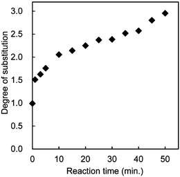 | ||
| Fig. 10 Effect of reaction time on the acetyl DS. Reprinted with permission from ref. 56. Copyright 2010, American Chemical Society. | ||
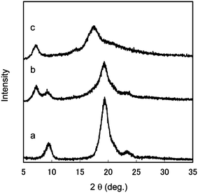 | ||
| Fig. 11 X-ray diffraction profiles of acetylated chitin nanofibers of (a) DS 0.99, (b) DS 1.81, and (c) DS 2.96. Reprinted with permission from ref. 56. Copyright 2010, American Chemical Society. | ||
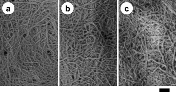 | ||
| Fig. 12 SEM images of acetylated chitin nanofiber samples of (a) DS 0.99, (b) DS 1.81, and (c) DS 2.96. The length of the scale bar is 200 nm. Reprinted with permission from ref. 56. Copyright 2010, American Chemical Society. | ||
4. Application of chitin nanofibers
4.1 Optically transparent chitin nanofiber–acrylic resin composite
One of the advantages of chitin nanofibers is their high filtering speed.48 When a water suspension containing 0.1% nanofibers was vacuum filtered to make a thin sheet, a suspension of chitin nanofibers was vacuum-filtered 9 times faster than cellulose nanofibers under the same conditions. This is because the hydroxyl groups at the C2 position of the cellulose molecules are replaced by more hydrophobic acetamide groups, and thus the chitin nanofibers are less dispersed in water than cellulose nanofibers, resulting in a higher filtering speed. This is a prominent advantage of chitin nanofibers over cellulose nanofibers to remove water from nanofibers and make a nanofiber sheet.Chitin nanofiber-reinforced composites have been prepared using the chitin nanofiber sheets thus obtained. Yano et al. have recently reported that cellulose nanofibers are a very promising material for reinforcing materials.57,58 Owing to the size effect, the nanocomposites are optically transparent even with a high fiber content. The study could be applicable for chitin nanofibers for transparent composites, since the transparency strongly depends on the fiber thickness. Therefore, we prepared chitin nanofiber composites with 11 different types of acrylic resins, and characterized their transparency, mechanical properties, and thermal expansion (Fig. 13).59 The chitin nanofiber sheets were impregnated with bi-functional acrylic resin monomers and photoinitiators. The resin-impregnated sheets were polymerized by UV irradiation. All nanocomposites had a high transparency, despite the high fiber content of 40 wt.% and 60 μm thickness (Fig. 14). To study the effect of the resin refractive index (RI) on the transparency of the nanocomposite, the regular light transmittances of the nanocomposite films at 600 nm vs. the RIs of their acrylic resins were measured (Fig. 15). Although the RIs of the resins used in this study were widely distributed from 1.468 to 1.540, the transmittances of the nanocomposites were high (72–90%). This was obviously due to the nano-size effect. Since the chitin nanofibers with 10–20 nm width were sufficiently thinner than the wavelength of visible light from approximately 400 nm to 800 nm, the transparencies of the nanocomposites were less affected by the variety of RIs of the resins.60 The transparent mechanism is of course inapplicable to a micro-sized reinforcement composite.61 To obtain the most transparent nanocomposite, the optimum RI value of the resin was around 1.50–1.51. In the case of DCP resin (RI: 1.50), the difference in transparency between the neat resin (91.2%) and the chitin nanocomposite (89.9%) was only 1.3%. By using the transparent mechanism, Shams et al. demonstrated an optically transparent crab-shell keeping its original shape.62 An important application of the finding is that a heterogeneous micro-scale crab shell chitin powder is also available to make transparent nanocomposites. This offers a simple approach to produce transparent composites.
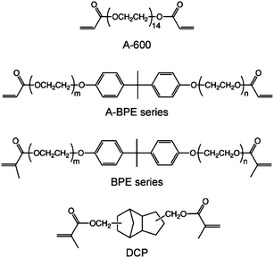 | ||
| Fig. 13 Chemical structures of the acrylic resins used in this study. Reproduced from ref. 59. Copyright 2011, the Royal Society of Chemistry. | ||
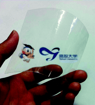 | ||
| Fig. 14 Appearance of DCP films reinforced with chitin nanofibers. Reproduced from ref. 59. Copyright 2011, the Royal Society of Chemistry. | ||
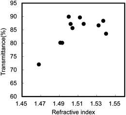 | ||
| Fig. 15 Regular light transmittance of chitin nanofiber composite films at 600 nm versus the refractive index of their acrylic resins. Reproduced from ref. 59. Copyright 2011, the Royal Society of Chemistry. | ||
Since chitin nanofibers have an antiparallel extended crystal structure, they have a high mechanical strength and Young's modulus. Therefore, chitin nanofibers are considered to be a useful reinforcing element to improve the mechanical properties of composite materials. Thus, tensile tests were carried out to study the reinforcing effect of the chitin nanofibers. The Young's moduli and tensile strengths of several types of acrylic resins and their chitin nanofiber composites are shown in Fig. 16 and 17, respectively. For the tests, the chitin nanofiber composite films were 50 mm long, 10 mm wide, and 60 mm thick, and the fiber content was approximately 40%. Although both rigid and soft resins were used in this study, the Young's moduli of all resins increased significantly by up to 3.0 GPa. The tensile strengths of all the nanocomposites also increased significantly by 20 MPa to 44 MPa, and even with a low strength resin, the tensile strength reached more than 30 MPa. These outstanding enhancements of mechanical properties strongly support the notion that a chitin nanofiber sheet with a high Young's modulus and a high tensile strength works effectively as a reinforcing element. It should be noted that a chitin nanofiber sheet can make a fragile resin ductile. Although DCP resin was brittle due to the high crosslinking density, the fracture strain of the DCP composite reinforced by chitin nanofibers increased three-fold.63
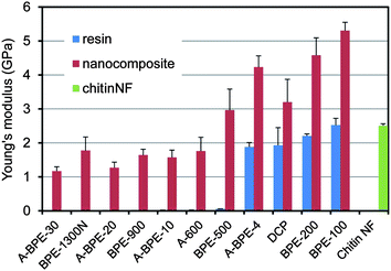 | ||
| Fig. 16 Young's modulii of acrylic resin films and their nanocomposites. Error bars show standard deviations. Reproduced from ref. 59. Copyright 2011, the Royal Society of Chemistry. | ||
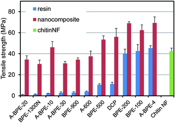 | ||
| Fig. 17 Tensile strength of acrylic resin films and their nanocomposites. Error bars show standard deviations. Reproduced from ref. 59. Copyright 2011, the Royal Society of Chemistry. | ||
Since the Young's modulus of a chitin nanofiber is estimated to be at least 150 GPa, the coefficient of thermal expansion (CTE) is very small.64,65 Therefore, chitin nanofibers are also applicable as a reinforcement agent to reduce the thermal expansion of resins (Fig. 18). The CTE of a chitin nanofiber sheet was only 9.8 ppm K−1. On the other hand, the CTEs of neat acrylic resins were quite high, ranging from 98.3 to 185.4 ppm K−1, and showed an inverse relationship to the Young's moduli. The CTEs of their nanocomposites decreased significantly to values from 29.5 to 17.5 ppm K−1. These values corresponded to a 70.0% to 90.6% decrease. Thus, chitin nanofibers with a low CTE and a high Young's modulus could decrease the thermal expansion of acrylic resins by a reinforcing effect. In conclusion, due to the nano-size structure and excellent mechanical properties of chitin nanofibers, the composites were highly transparent and flexible, and had a low thermal expansion, a high Young's modulus and a high tensile strength.
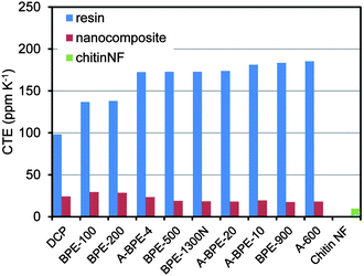 | ||
| Fig. 18 Coefficient of thermal expansion of (meth)acrylic resin films and their nanocomposites. Reproduced from ref. 59. Copyright 2011, the Royal Society of Chemistry. | ||
4.2 Chitin nanofiber sheets for chiral separation
Optically active compounds have garnered much attention in the fields of pharmaceuticals, agrochemicals, liquid crystals, and so on. Optical resolution by liquid chromatography (LC) has become a useful method for obtaining optical isomers.66 Since cellulose and amylose are naturally occurring optically active polymers, it is known that these polysaccharides and their derivatives show chiral recognition.67–70 Therefore, many of them are commercially available to separate a wide range of racemic compounds into enantiomers. We found that chitin nanofiber sheets showed chiral separation ability.71 A chitin nanofiber sheet of 85 μm thickness obtained by filtration was fixed between two chambers of a permeation cell. An aqueous solution of a racemic mixture of amino acids, glutamic acid (Glu), phenylalanine (Phe), and lysine (Lys), was placed on one side of the chamber. The amounts of the D- and L-isomers were determined by the LC equipment. The driving force for sheet transport of amino acids was the concentration gradient. The D-isomers of all amino acids were transported preferentially to the L-isomer. The permselectivities toward D-isomers of Phe, Glu, and Lys, which were defined as the flux ratio divided by the concentration ratio, were 1.16, 1.04, and 1.07, respectively. Given their characteristic nano-form and excellent physical properties, chitin nanofiber sheets are expected to be candidates for a membrane for chiral separation.4.3 Bioactivities of chitin nanofibers
It has been reported that chitin and its derivatives have nonspecific antiviral and antitumor activities.72,73 It was suggested that the size of chitin influences its effects on immune cells.74,75 Therefore, chitin nanofibers are considered to have great potential for application in tissue engineering scaffolds, drug delivery, and wound dressing.76 However, there has been no report on the in vivo effects of chitin nanofibers after oral administration. Inflammatory bowel disease (IBD) is a commonly occurring group of conditions characterized by inflammation in the intestinal tract. Crohn's disease (CD) and ulcerative colitis (UC) account for the majority of the cases of these conditions.77 A model of dextran sulfate sodium (DSS)-induced colitis is one common model of IBD.78 We evaluated the preventive effects of chitin nanofibers in a mouse model of DSS-induced acute UC.79The effects of chitin nanofibers on the disease activity index (weight loss, loose stools, and bleeding) in DSS-induced acute UC mice were studied. The chitin nanofiber-administered group exhibited a significantly reduced disease activity index. Although the administration of DSS shortened the colon length, colon lengths in the chitin nanofiber groups were significantly greater than those in the control group. Damage in the intestinal mucosa was microscopically evaluated (Fig. 19). On the 6th day in the control group, severe erosions, crypt destruction, edema, and some ulcers were observed. On the other hand, in the chitin nanofiber group, erosions, crypt destruction, and edema were markedly suppressed compared with those in the control. The numbers of myeloperoxidase (MPO)-positive cells were measured (Fig. 20). Although the numbers of MPO-positive cells gradually increased with time, in the chitin nanofiber group, the numbers of MPO-positive cells were significantly lower than those in the control group. Moreover, the serum interleukin (IL)-6 concentration was significantly lower in the chitin nanofiber group than in the control group.
 | ||
| Fig. 19 Effect of chitin nanofiber administration on histopathological changes in DSS-induced acute UC mice. The colon was fixed, and tissue sections were stained with hematoxylin and eosin. Data are presented for 1 mouse each from the control (a), chitin nanofiber (b), and chitin powder (c) groups on day 6. Erosion is indicated by an arrow. Bar = 100 mm. Reproduced with permission from ref. 79. Copyright 2012, Elsevier. | ||
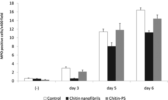 | ||
| Fig. 20 Effect of chitin nanofibers administration on the MPO-positive cells counts/400× field in the colons of DSS-induced acute UC mice. Data represent the means ±S.E. of 60 fields/400× field in each group. Values are compared among control, chitin nanofibers, and chitin powder (PS) groups. Reproduced with permission from ref. 79. Copyright 2012, Elsevier. | ||
Thus, chitin nanofibers improved clinical symptoms, colon inflammation, and histological tissue injury in the DSS-induced acute UC mouse model. As MPO is a marker of oxidative stress, high MPO activities were observed in a DSS-induced UC model.80 IL-6 is a central cytokine in IBD that contributes to enhanced T-cell survival and apoptosis resistance in the lamina propria at sites of inflammation.81 Therefore, the chitin nanofibers suppressed the inflammation caused by acute UC by suppressing the MPO-mediated activation of inflammatory cells such as leukocytes and decreasing serum IL-6 concentrations.
5. Conclusions and outlook
Chitin nanofibers were prepared from the exoskeletons of crabs and prawns and the cell walls of mushrooms by the removal of matrix substances followed by mechanical treatment. The obtained chitin nanofibers formed a fine nanofiber network with a uniform width of approximately 10–20 nm and a high aspect ratio. Since the acidic condition induces electrostatic repulsion, chitin was easily converted to nanofibers by the repulsive force. Since chitin is obtained from crab and prawn shells, it is considerably more expensive than cellulose which is easily obtained from wood cell-walls. This is a disadvantage for chitin nanofibers. On the other hand, chitin nanofibers have several advantages over cellulose nanofibers as follows: (1) Chitin, chitosan, and their derivatives are known to exhibit a variety of bioactivities.82,83 (2) Chitin nanofibers can be easily and immediately prepared from dry chitin samples assisted by electrostatic repulsion.47 (3) The filtering speed to remove water from the sample is greater than that of cellulose nanofibers.48 (4) Most of the matrix can be removed from crab and prawn shells by a conventional method.32 On the other hand, complete removal of hemicelluloses from wood is difficult.84 (5) Naturally rare cationic-charged nanofibers are prepared by surface deacetylation of chitin nanofibers.51 This is a key tool for designing smart materials by means of ionic complex or self-organization approaches. Thus, the produced amino group is a highly reactive functional group, which enables surface modifications. Therefore, utilizing these advantages is important to define the separate roles of chitin and cellulose for expanding the application of chitin nanofibers.This simple and efficient process allowed us to obtain homogeneous chitin nanofibers in their original state in large amounts. We believe that nanofibers with a characteristic morphology, very high surface area, and excellent mechanical properties have great potential for novel green nanomaterials. We presented a variety of applications of chitin nanofibers, including optically transparent nanocomposites, chiral separation membranes, and functional foods or drugs for inflammatory bowel disease patients. In general, chitin is insoluble in water. On the other hand, since the chitin nanofibers could be dispersed homogeneously in water, they were easy to handle and shape into the desired forms. This characteristic led to the above-described applications of chitin nanofibers. We expect that other novel applications of chitin nanofibers will be discovered in the near future.
Notes and references
- Y. Xia, P. Yang, Y. Sun, Y. Wu, B. Mayers, B. Gates, Y. Yin, F. Kim and H. Yan, Adv. Mater., 2003, 15, 353–389 CrossRef CAS.
- D. Li and Y. Xia, Adv. Mater., 2004, 16, 1151–1170 CrossRef CAS.
- Z. M. Huang, Y. Z. Zhang, M. Kotaki and S. Ramakrishna, Compos. Sci. Technol., 2003, 63, 2223–2253 CrossRef CAS.
- S. Ramakrishna, K. Fujihara, W. E. Teo, T. Yong, Z. Ma and R. Ramaseshan, Mater. Today, 2006, 9, 40–50 CrossRef CAS.
- Z. M. Huang, Y. Z. Zhang, M. Kotaki and S. Ramakrishna, Compos. Sci. Technol., 2003, 63, 2223–2253 CrossRef CAS.
- T. J. Sill and H. A. Recum, Biomaterials, 2008, 29, 1989–2006 CrossRef CAS.
- I. Sakurada, Y. Nukushina and T. Ito, J. Polym. Sci., 1962, 57, 651–660 CrossRef CAS.
- D. H. Page and F. Elhosseiny, J. Pulp Pap. Sci., 1983, 84, 99–100 Search PubMed.
- T. Nishino, I. Matsuda and K. Hirao, Macromolecules, 2004, 37, 7683 CrossRef CAS.
- A. F. Turbak, F. W. Synder and K. R. Sandberg, J. Appl. Polym. Sci.: Appl. Polym. Symp., 1983, 37, 815–827 CAS.
- T. Taniguchi and K. Okamura, Polym. Int., 1998, 47, 291–294 CrossRef CAS.
- S. Iwamoto, A. N. Nakagaito, H. Yano and M. Nogi, Appl. Phys. A: Mater. Sci. Process., 2005, 81, 1109–1112 CrossRef CAS.
- A. Chakraborty, M. Sain and M. Kortschot, Holzforschung, 2005, 59, 102–107 CrossRef CAS.
- A. Bhatnagar and M. Sain, J. Reinf. Plast. Compos., 2005, 24, 1259–1268 CrossRef CAS.
- H. P. Zhao, X. Q. Feng and H. Gao, Appl. Phys. Lett., 2007, 90, 073112 CrossRef.
- M. Pääkkö, M. Ankerfors, H. Kosonen, A. Nykänen, S. Ahola, M. Österberg, J. Rukolainen, J. Laine, P. T. Larsson, O. Ikkala and T. Lindström, Biomacromolecules, 2007, 8, 1934–1941 CrossRef.
- K. Abe, S. Iwamoto and H. Yano, Biomacromolecules, 2007, 8, 3276–3278 CrossRef CAS.
- K. Abe and H. Yano, Cellulose, 2009, 16, 1017–1023 CrossRef CAS.
- K. Abe and H. Yano, Cellulose, 2010, 17, 271–277 CrossRef CAS.
- S. Ifuku, M. Adachi, M. Morimoto and H. Saimoto, Sen'i Gakkaishi, 2011, 67, 86–90 CrossRef CAS.
- A. Isogai, T. Saito and H. Fukuzumi, Nanoscale, 2011, 3, 71–85 RSC.
- T. Saito, Y. Nishiyama, J.-L. Putaux, M. Vignon and A. Isogai, Biomacromolecules, 2006, 7, 1687–1691 CrossRef CAS.
- T. Saito, S. Kimura, Y. Nishiyama and A. Isogai, Biomacromolecules, 2007, 8, 2485–2491 CrossRef CAS.
- T. Saito, M. Hirota, N. Tamura, S. Kimura, H. Fukuzumi, L. Heux and A. Isogai, Biomacromolecules, 2009, 10, 1992–1996 CrossRef CAS.
- N. K. Gopalan and A. Dufresne, Biomacromolecules, 2003, 4, 657–665 CrossRef.
- D. Raabe, P. Romano, C. Sachs, H. Fabritius, A. Al-Sawalmih, S. B. Yi, G. Servos and H. G. Hartwig, Mater. Sci. Eng., A, 2006, 421, 143–153 CrossRef.
- P. Y. Chen, A. Y. M. Lin, A. J. McKittrick and M. A. Meyers, Acta Biomater., 2008, 4, 587–596 CrossRef.
- M. M. Giraud-guille, Tissue Cell, 1984, 16, 75–92 CrossRef CAS.
- D. Raabe, C. Sachs and P. Romano, Acta Mater., 2005, 53, 4281–4292 CrossRef CAS.
- J. B. Zeng, Y. S. He, S. L. Li and Y. Z. Wang, Biomacromolecules, 2012, 13, 1–11 CrossRef CAS.
- S. Ifuku, M. Nogi, K. Abe, M. Yoshioka, M. Morimoto, H. Saimoto and H. Yano, Biomacromolecules, 2009, 10, 1584–1588 CrossRef CAS.
- K. Shimahara and Y. Takiguchi, in Methods in Enzymology, ed. W. A. Wood and S. T. Kellogg, Academic Press, California, CA, 1998, vol. 6, pp. 417–423 Search PubMed.
- J. N. BeMiller and R. L. Whistler, J. Org. Chem., 1962, 27, 1161–1164 CrossRef CAS.
- N. K. Gopalan and A. Dufresne, Biomacromolecules, 2003, 4, 657–665 CrossRef.
- R. Minke and J. Blackwell, J. Mol. Biol., 1978, 120, 167–181 CrossRef CAS.
- S. Ifuku, M. Nogi, K. Abe, M. Yoshioka, M. Morimoto, H. Saimoto and H. Yano, Carbohydr. Polym., 2011, 84, 762–764 CrossRef CAS.
- P. Chen, A. Y. Lin, J. Mckittrick and M. A. Meyers, Acta Biomater., 2008, 4, 587–596 CrossRef.
- I. Yano, Kagaku To Seibutsu, 1977, 15, 328–336 CrossRef CAS.
- G. O. Michalenko, H. R. Hohl and D. Rast, J. Gen. Microbiol., 1976, 92, 251–262 CAS.
- S. Zivanovic, R. Buescher and S. K. Kim, J. Food Sci., 2003, 68, 1860–1865 CrossRef CAS.
- H. Kunzek, S. Müller, S. Vetter and R. Godeck, Eur. Food Res. Technol., 2002, 214, 361–376 CrossRef CAS.
- F. Guillon and M. Champ, Food Res. Int., 2000, 33, 233–245 CrossRef.
- S. Ifuku, R. Nomura, M. Morimoto and H. Saimoto, Materials, 2011, 4, 1417–1425 CrossRef CAS.
- T. N. Ivshina, S. D. Artamonova, V. P. Ivshin and F. F. Sharnina, Appl. Biochem. Microbiol., 2009, 45, 313–318 CrossRef CAS.
- Y. Fan, T. Saito and A. Isogai, Biomacromolecules, 2008, 9, 192–198 CrossRef CAS.
- Y. Fan, T. Saito and A. Isogai, Biomacromolecules, 2008, 9, 1919–1923 CrossRef CAS.
- S. Ifuku, M. Nogi, K. Abe, M. Yoshioka, M. Morimoto, H. Saimoto and H. Yano, Carbohydr. Polym., 2011, 84, 762–764 CrossRef CAS.
- M. I. Shams, S. Ifuku, M. Nogi, T. Oku and H. Yano, Appl. Phys. A: Mater. Sci. Process., 2011, 102, 325–331 CrossRef CAS.
- R. Kose and T. Kondo, Sen'i Gakkaishi, 2011, 67, 91–95 CrossRef CAS.
- Y. Watanabe, S. Kitamura, K. Kawasaki, T. Kato, K. Uegaki, K. Ogura and K. Ishikawa, Biopolymers, 2011, 95, 833–839 CrossRef CAS.
- Y. Fan, T. Saito and A. Isogai, Carbohydr. Polym., 2010, 79, 1046–1051 CrossRef CAS.
- W. G. Glasser, R. Taib, R. K. Rajesh and R. Kander, J. Appl. Polym. Sci., 1999, 73, 1329–1340 CrossRef CAS.
- D. Y. Kim, Y. Nishiyama and S. Kuga, Cellulose, 2002, 9, 361–367 CrossRef CAS.
- M. Nogi, K. Abe, K. Handa, F. Nakatsubo, S. Ifuku and H. Yano, Appl. Phys. Lett., 2006, 89, 233123 CrossRef.
- S. Ifuku, M. Nogi, K. Abe, K. Handa, F. Nakatsubo and H. Yano, Biomacromolecules, 2007, 8, 1973–1978 CrossRef CAS.
- S. Ifuku, S. Morooka, M. Morimoto and H. Saimoto, Biomacromolecules, 2010, 11, 1326–1330 CrossRef CAS.
- H. Yano, J. Sugiyama, A. N. Nakagaito, M. Nogi, T. Matsuura, M. Hikita and K. Handa, Adv. Mater., 2005, 17, 153–155 CrossRef CAS.
- M. Nogi, S. Ifuku, K. Abe, K. Handa, A. N. Nakagaito and H. Yano, Appl. Phys. Lett., 2006, 88, 133124 CrossRef.
- S. Ifuku, S. Morooka, A. N. Nakagaito, M. Morimoto and H. Saimoto, Green Chem., 2011, 13, 1708–1711 RSC.
- M. Nogi, K. Handa, A. N. Nakagaito and H. Yano, Appl. Phys. Lett., 2005, 87, 243110 CrossRef.
- H. Sato, H. Iba, T. Naganuma and Y. Kagawa, Philos. Mag. B, 2002, 82, 1369–1386 CAS.
- M. I. Shams, M. Nogi, L. A. Berglund and H. Yano, Soft Matter, 2012, 8, 1369–1373 RSC.
- Y. Okahisa, A. Yoshida, S. Miyaguchi and H. Yano, Compos. Sci. Technol., 2009, 69, 1958–1961 CrossRef CAS.
- J. Vincent and U. Wegst, Arthropod Struct. Dev., 2004, 33, 187–199 CrossRef.
- M. Wada and Y. Saito, J. Polym. Sci., Part B: Polym. Phys., 2001, 39, 168–174 CrossRef CAS.
- S. Ahuja, in Chiral Separations by Liquid Chromatography, ed. S. Ahuja, American Chemical Society, Washington, DC, 1991, p. 1 Search PubMed.
- Y. Okamoto and Y. Kaida, J. Chromatogr., A, 1994, 666, 403–419 CrossRef CAS.
- S. Yuasa, A. Shimada, K. Kameyama, M. Yasui and K. Adzuma, J. Chromatogr. Sci., 1980, 18, 311–314 CAS.
- T. Fukuhara, M. Isoyama, A. Shimada, M. Itoh and S. Yuasa, J. Chromatogr., A, 1987, 387, 562–565 CrossRef CAS.
- G. Gubitz, W. Jellenz and D. Schonleber, J. High Resolut. Chromatogr., 1980, 3, 31–32 Search PubMed.
- Y. Sueyoshi, T. Hashimoto, M. Yoshikawa and S. Ifuku, Sustainable Agriculture Research, 2011, 1, 42–47 Search PubMed.
- Y. Shibata, L. A. Foster, J. F. Bradfield and Q. N. Myrvik, J. Immunol., 2000, 164, 1314–1321 CAS.
- Y. Shibata, I. Honda, J. P. Justice, M. R. Van Scott, R. M. Nakamura and Q. N. Myrvik, Infect. Immun., 2001, 69, 6123–6130 CrossRef CAS.
- C. A. Da Silva, D. Hartl, W. Liu, C. G. Leeand and J. A. Elias, J. Immunol., 2008, 181, 4279–4286 CAS.
- C. G. Lee, C. A. Da Silva, J. Y. Lee, D. Hartl and J. A. Elias, Curr. Opin. Immunol., 2008, 20, 684–689 CrossRef CAS.
- R. A. A. Muzzarelli, P. Morganti, G. Morganti, P. Palombo, M. Palombo, G. Biagini, M. M. Belmonte, F. Giantomassi, F. Orlandi and C. Muzzarelli, Carbohydr. Polym., 2007, 70, 274–284 CrossRef CAS.
- G. Morrison, B. Headon and P. Gibson, Aust. Fam. Physician, 2009, 38, 956–961 Search PubMed.
- S. Melgar, A. Karlsson and E. Michaelsson, Am. J. Physiol.: Gastrointest. Liver Physiol., 2005, 288, G1328–G1338 CrossRef CAS.
- K. Azuma, T. Osaki, T. Wakuda, S. Ifuku, H. Saimoto, T. Tsuka, T. Imagawa, Y. Okamoto and S. Minami, Carbohydr. Polym., 2012, 87, 1399–1403 CrossRef CAS.
- Y. Naito, T. Takagi and T. Yoshikawa, J. Clin. Biochem. Nutr., 2007, 41, 18–26 CrossRef CAS.
- J. Mudeter and M. F. Neurath, Inflammatory Bowel Dis., 2007, 13, 1016–1023 CrossRef.
- Y. Okamoto, K. Shibazaki, S. Minami, A. Matsuhashi, S. Tanioka and Y. Shigemasa, J. Vet. Med. Sci., 1995, 57, 851–854 CrossRef CAS.
- S. Tokura, N. Nishi, S. Nishimura and O. Somorin, Sen’i Gakkaishi, 1983, 39, 45–49 CrossRef.
- S. Iwamoto, K. Abe and H. Yano, Biomacromolecules, 2008, 9, 1022–1026 CrossRef CAS.
| This journal is © The Royal Society of Chemistry 2012 |

