Subtle regulation of the micro- and nanostructures of electrospun polystyrene fibers and their application in oil absorption
Jinyou
Lin
acd,
Bin
Ding
*abc,
Jianmao
Yang
e,
Jianyong
Yu
*c and
Gang
Sun
f
aState Key Laboratory for Modification of Chemical Fibers and Polymer Materials, College of Materials Science and Engineering, Donghua University, Shanghai, 201620, China. E-mail: binding@dhu.edu.cn; Fax: +86-21-62378202; Tel: +86-21-62378202
bEngineering Research Center of Technical Textiles, Ministry of Education, Donghua University, Shanghai, 201620, China
cNanomaterials Research Center, Research Institute of Donghua University, Shanghai, 200051, China. E-mail: yujy@dhu.edu.cn
dCollege of Textiles, Donghua University, Shanghai, 201620, China
eResearch Center for Analysis and Measurement, Donghua University, Shanghai, 201620, China
fFibers and Polymer Science, University of California, Davis, CA 95616, USA
First published on 9th November 2011
Abstract
In this study, we conducted a subtle regulation of micro- and nanostructures of electrospun polystyrene (PS) fibers via tuning the molecular weights of the polymers with different sources, solvent compositions, and solution concentration. The surface morphology and porous structures of as-prepared PS fibers were characterized, and a full and intuitive observation of the porous structures as well as a tentative account of the formation of porous structures was presented. Additionally, the porous PS fibrous mats showed much higher oil absorption capacities than those of commercial polypropylene fibers in the form of a non-woven fabric, which displays a bight future for oil spill cleanups. We believe that such regulation of micro- and nanostructures of the PS fibers will widen the range of their applications in self-cleaning materials, ultra-high sensitivity sensors, tissue engineering, ion exchange materials, etc.
Introduction
Throughout the millennia, nature has developed materials and objects that are endowed with fascinatingly hierarchical structures, from the nanoscale to the microscale, displaying some unique properties, such as self-cleaning, structural colours, thermal insulation, dry adhesion and so on.1 Interestingly, many of these features were achieved by structuring the given materials rather than by changing their composition. Inspired by nature, a number of processing techniques made it possible to design and manufacture diverse nanomaterials with expected hierarchical structures and functionalities.2Over the past two decades, one-dimensional nanomaterials such as nanofibers have attracted tremendous interest due to their typical properties (e.g., large surface area-to-volume ratio, high porosity, and flexibility in surface functionalities) and intriguing applications in many areas (e.g., tissue engineering, filtration, catalysis, self-cleaning, drug delivery, sensors, dye-sensitized solar cells, etc.).3–5 Compared with other methods of nanofiber generation like drawing, self-assembly, template synthesis, phase separation, sea-island bicomponent spinning, etc., electrospinning is a well recognized and effective method to fabricate fibers with diameters ranging from micrometres down to several nanometres from an electrically driven jet of polymer liquid.6,7
The formation of nanofibers viaelectrospinning involves applying a high voltage on the polymer solution to deform it as a pendent drop at the tip of the spinneret. When the strength of the electric field exceeds a critical value, a thin fluid jet will be ejected from the deformed conical drop known as the Taylor cone, which is caused by the competition between the surface tension and electrostatic forces acting on the solution. The charged viscoelastic jet, which is elongated and accelerated by the electrical forces, experiences a series of instabilities, solvent evaporation and solidification, and then is deposited on a grounded target in the form of a non-woven fabric.6,8,9
In general, electrospun nanofibers are usually circular in cross-section and have a solid interior which is collected randomly as fibrous mats.9,10 Hierarchical structures, especially the micro- and nanostructures within electrospun fibers, are extremely important for functionalization of the fibers and to extend their properties. Furthermore, the specific surface area of an individual electrospun fiber can be considerably increased when its structure is transformed from a solid to a porous one,11 which is beneficial to many applications. Recently, electrospun nanofibers with some specific hierarchical structures, i.e., wrinkled surfaces, core–sheath, hollow, porous and nano-nets have also been yielded when appropriate processing parameters and new designs of the spinning setup were employed,3 which broadens the range of applications in superhydrophobic surfaces,12dye-sensitized solar cells,13 sensors,4,14,15 and catalysis.16
Polystyrene (PS), a common thermoplastic polymer with low surface energy due to its CH groups, has been widely used to fabricate artificially superhydrophobic surfaces viaelectrospinning.17–19 A considerable amount of research has been conducted on the variables in electrospun PS fibers including solvent type, solvent conductivity, processing parameters and relative humidity.20–23 By varying these variables, the electrospun PS fibers with typically fine morphologies such as flat24 and bead structures,17,25 as well as porous structures,6,11,25,26etc. have been obtained directly without any post-treatment process. Although porous PS fibers have been investigated by a number of researchers, and some simulation studies pertaining to the effects of different processing parameters on structure evolution were also reported,26–28 to the best of our knowledge, there are still few reports on the formation of electrospun PS fibers with micro- and nanostructuresviaelectrospinning directly, especially providing a full and intuitive observation of the porous structures within the resultant fibers, both interior and exterior.
In this study, we investigated the variables, such as the molecular weights of the polymers with different sources, solvent compositions, solution concentration, as well as how to influence the micro-and nanostructures of electrospun PS fibers. The surface morphology and porous structures of as-prepared PS fibers were characterized, and a full and intuitive observation of the porous structures as well as a tentative account for the formation of porous structures is presented. In addition, we measured the absorption capacities of a selected porous PS fibrous mat as a sorbent to absorb oils placed on water formed thin films.
Experimental section
Materials
Polystyrene (PS) with molecular weights of Mw = 350 000 g mol−1 and Mw = 208 000 g mol−1 was purchased from Aldrich and Wako, respectively. Tetrahydrofuran (THF) and N,N-dimethylformamide (DMF) were purchased from Shanghai Chemical Reagents Co., Ltd, China. The motor oil and sunflower seed oil were obtained from TOTAL Lubricants China Co., Ltd. and Standard Foods China Co., Ltd., respectively. The oil properties were investigated and listed in Table 1.| Oil | Viscosity (mPa s−1) | Density (g cm−3) |
|---|---|---|
| Motor oil | 270 | 0.859 |
| Sunflower seed oil | 50 | 0.964 |
Experimental procedures
PS (Mw = 208 000 g mol−1) solutions were prepared at concentrations of 10, 20, and 30 wt% by using THF![[thin space (1/6-em)]](https://www.rsc.org/images/entities/char_2009.gif) :DMF mixtures with weight ratios of 100:0, 80:20, 60:40, 50:50, 40/:, 20:80, and 0:100, respectively. A 20 wt% PS (Mw = 350 000 g mol−1, Aldrich) solution in THF:DMF with a weight ratio of 50:50 was also prepared.
:DMF mixtures with weight ratios of 100:0, 80:20, 60:40, 50:50, 40/:, 20:80, and 0:100, respectively. A 20 wt% PS (Mw = 350 000 g mol−1, Aldrich) solution in THF:DMF with a weight ratio of 50:50 was also prepared.
The PS solution was placed in a syringe connected with a needle that was controlled by a syringe pump (LSP02-1B, Baoding Longer Precision Pump Co., Ltd, China). The solution feeding rate was controlled at 4 mL h−1. A high voltage power supply (DW-P303-1ACD8, Tianjin Dongwen High Voltage Co., China) was used to generate a potential difference of 20 kV between the needle and an aluminum foil-covered grounded metallic rotating roller rotated at 100 rpm. The work distance (WD) was kept at 15 cm. The ambient relative humidity used in the chamber was selected to be 40% and kept constant. All the experiments were carried out at 25 °C.
Characterization
The viscosity of polymer solutions and commercial oils was determined by using a rotational viscometer (NDJ-79, Shanghai Changji Geological Instruments Co., Ltd China). The morphology and cross-section of the electrospun PS fibers were examined by field emission scanning electron microscopy (FE-SEM) (S-4800, Hitachi Ltd, Japan). The micro- and nanostructures of the PS fibers were characterized by using a Micromeritics ASAP-2020 analyzer (Micromeritics, USA). The specific surface area (SSA) of the as-spun fibrous mats was obtained from the nitrogen adsorption data in the relative pressure range from 0.03 to 0.35 by using the Brunauer–Emmett–Teller method. The pore size distribution, total pore volume and average pore width of the fibrous mats were calculated from the desorption branch using the Barrett–Joyner–Halenda method.Oil absorption measurement
All the oil absorption measurements were carried out at 25 °C using following steps. 10 g oil was added into the 250 mL beaker containing 150 mL water. The oil forms a thin film on the water due to its lower density compared to water. 0.1 g of the sorbent (porous PS fibrous mats and commercial polypropylene (PP) fibers) was dropped onto the oil film. The absorption behavior of the sorbent was recorded by a conventional digital camera as time went on. After 1 h absorption, the wet sorbent was taken out using a nipper and drained for 3 min. The oil absorption capacities for these sorbents were obtained from the following equation: | (1) |
Result and discussion
Fig. 1 shows the FE-SEM images of electrospun PS fibers from 20 wt% PS with different molecular weights (Mw = 350 000 g mol−1 and Mw = 208 000 g mol−1) in a 50:50 mixture of THF:DMF. The most distinctive difference between the resultant PS fibers is that the fibers formed with the higher molecular weight display wrinkled surfaces with aligned wrinkles along the fiber axis; however, the fibers formed with the lower molecular weight have rough surfaces with many micro- or nanoprotrusions resembling islands. When the fluid jet containing polymer chains and solvent molecules ejects from the Taylor cone contacting the air (Fig. 2a), a thin and elastic glassy shell is formed on the surface of the fluid jet rapidly due to solvent evaporation and solidification. Simultaneously, the non-solvent particles (air and moisture) will penetrate into the fluid jet through the shell while the solvent will diffuse out from the core of the jet (Fig. 2b). In this process, a deformation mismatch between the shell and the core will occur under the stretching of electrical force due to core shrinkage during solvent diffusion,29 and thus the wrinkled surfaces are formed as shown in Fig.1a.
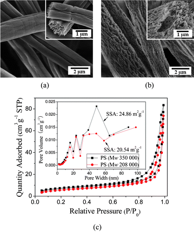 | ||
| Fig. 1 FE-SEM images of electrospun PS fibers formed with two molecular weights of (a) Mw = 350 000 g mol−1 and (b) Mw = 208 000 g mol−1. (c) Nitrogen adsorption–desorption isotherms and pore size distribution curves (inset) of the PS fibers formed with various molecular weight. | ||
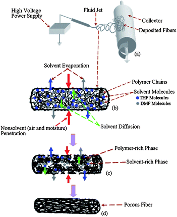 | ||
| Fig. 2 Schematic diagram illustrating the formation process of porous fibers during electrospinning. | ||
As the molecular weight of the PS decreased, the viscosity of the 20 wt% PS solutions decreased from 190 to 73.5 mPa s−1 in the same solvent system due to less entanglement of PS molecular chains within the solution.30 Less entanglements of the polymer chains within the PS solution may accelerate solvent evaporation and diffusion, resulting in the occurrence of rapid phase separation on the surfaces of the fluid jet. Subsequently, the results of phase separation were fixed by solidification, creating a rough surface with many micro- or nanoprotrusions as shown in Fig. 1b. High molecular weight PS resulting in the wrinkled fiber surfaces is in good agreement with previous observation.26
The cross-sections of PS fibers indicate that the cores of these fibers are highly porous rather than solid (insets of Fig. 1a and 1b). This is related to phase separation and solidification in the core of the fluid jet. When moisture in the air diffused into the fluid jet, the solution composition changed, and combined with solvent evaporation, cooled the fluid jet rapidly, thus the jet became thermodynamically unstable and phase separation occurred within the fluid jet yielding a polymer-rich phase and a solvent-rich phase (Fig. 2c).22,25 The concentrated polymer-rich phase eventually solidified into the matrix and the solvent-rich phase transformed into the pores as the solvent diffused out, being filled with nonsolvent particles, forming a porous fiber (Fig. 2d). Additionally, the stretching resulting from the electrical force deformed the polymer matrix and pores within the fibers, making the microfibrils present in the cores of the fibers (inset of Fig. 1a and 1b).
Fig. 1c shows the nitrogen physisorption (adsorption–desorption) isotherms and pore size distribution curves of the PS fibers formed with different molecular weights. The isotherms could be categorized as type II with a distinct hysteresis loop which is characteristic of mesopores (2–50 nm pore width) and macropores (>50 nm pore width) according to the International Union and Applied Chemistry (IUPAC) classification.31,32 Hence, the quantity of N2 adsorbed at a high relative pressure (>0.8 P/P0) mainly resulted from the macropores and mesopores developed on the outer surface and the porous core. The inset of Fig. 1c clearly illustrates that the pore size was in the range of 2–100 nm. The fibers formed with high molecular weight PS showed much larger pore volumes and a smaller pore size, which agreed very well with the FE-SEM observation (Fig. 1a, exhibiting densely porous cores with aligned microfibrils). These highly aligned microfibrils contributed a much higher SSA to the resultant fibers formed with high molecular weight PS, up to 24.86 m2 g−1.
FE-SEM images of fibers electrospun from 20 wt% PS (Mw = 208 000 g mol−1) solutions of various solvent compositions showed all the fiber diameters in the micrometre range (Fig. 3). The pores with an average diameter of approximately 40 nm were densely packed on the fiber surfaces electrospun from a highly volatile solvent, THF only (Fig. 3a). It can be seen that the fiber comprised a porous sheath and a solid core (inset of Fig. 3a). The pore formation on the fiber surfaces can be attributed to the rapid phase separation induced by solvent evaporation and subsequent solidification.33 A similar result was also reported by Megelski et al., and thermally induced phase separation and vapor-induced phase separation were regarded as possible reasons for the pore formation on the fiber surfaces.22
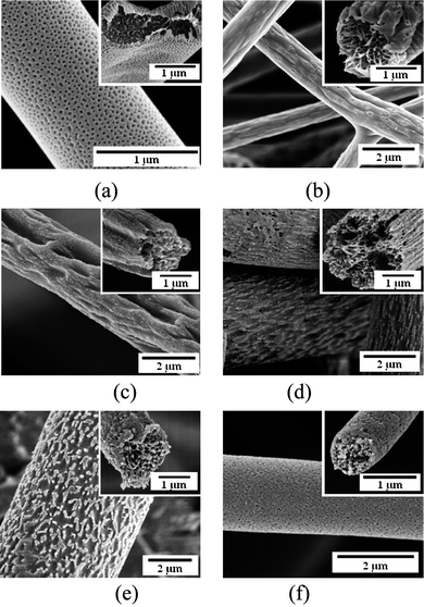 | ||
| Fig. 3
FE-SEM images of the PS (Mw = 208 000 g mol−1) fibers formed from various weight ratios of THF:DMF in solvent: (a) 100:0, (b) 80:20, (c) 60:40, (d) 40:60, (e) 20:80, and (f) 0:100, respectively. | ||
The pores on fiber surfaces disappeared but wrinkled surfaces emerged when a solvent mixture with 20% DMF was used (Fig. 3b). The porous core was clearer than that of the fibers electrospun from THF only (inset of Fig. 3b). With the increasing DMF percentage in the solvent mixtures, the fiber surfaces were coarsened with large pits and grooves as shown in Fig. 3c. As the DMF content further increased, the fibers surfaces displayed the sea-island morphology (the nano/micro protrusions resemble islands) with the nanopores presented on the surfaces, and the porous structure appeared to be throughout the cross-sections of these fibers (Fig. 3d and 3e). The structural features of porous surfaces became less clear with the fibers formed from DMF only (Fig. 3f). The difference in the porous structure of these resultant fibers can be attributed to the competition between the rapid phase separation and solidification resulting from the mutual diffusion of the solvent within the jet and the surrounding moisture due to the different solvent compositions utilized in electrospinning.22,25
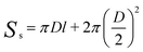
To obtain the SSA of solid nonporous fiber with circular cross-section, electrospun fibers can be assumed to possess infinite length, thus we can get the surface area of a single fiber as follows:11
 | (2) |
 | (3) |
 | (4) |
 | (5) |
 | (6) |
If the density of the electrospun PS fiber is approximate to the initial polymer (ρ = 1.05 g cm−3), the relationship between the theoretical SSA of fibers and fiber diameters is shown in Fig. 4a. It is obviously shown that the theoretical SSA of fibers is insensitive to the fiber diameter in the micrometre range (1–4 μm).
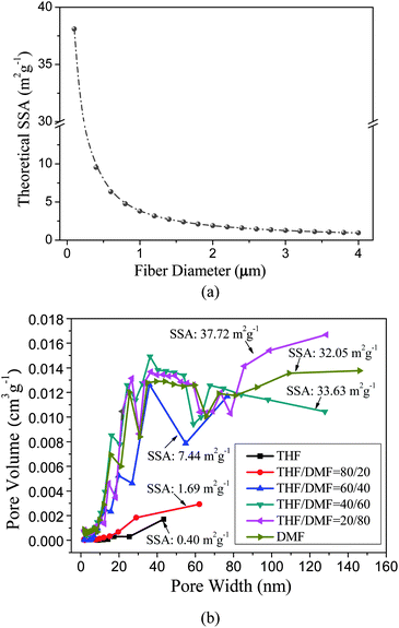 | ||
| Fig. 4 (a) The theoretical SSA of electrospun PS fibers as a function of the fiber diameters; (b) the pore size distribution curves and SSA of the corresponding PS fibers formed from various weight ratios of THF:DMF solvent as shown in Fig. 3. | ||
The fibers electrospun from THF only show the lowest experimental SSA of 0.40 m2 g−1 (total pore volume is only 0.002 cm3 g−1) because the nanopores are only on the fiber surfaces, whereas fibers formed from DMF only show a sharp increase in SSA (32.05 m2 g−1) (total pore volume is 0.200 cm3 g−1) due to its porous core (Fig. 4b), reflecting an increase of a factor of 80 and of 100 for the SSA and total pore volume, respectively. The pore size distribution curves of the PS fibers formed from THF and DMF, respectively, are also observed to mutually agree with their different values of SSA. As the THF:DMF mix ratio changed, the SSA shows a unimodal distribution peaking at a 20:80 THF:DMF mix ratio with a value of 37.72 m2 g−1 (total pore volume is 0.274 cm3 g−1) (Fig. 4b). Based on the results, it can be concluded that the increase in SSA of PS fibers was largely dependent on the introduction of porous structures into as-spun fibers. As a result, both the SSA and surface morphology of the PS fibers can be regulated by tuning the solvent compositions.
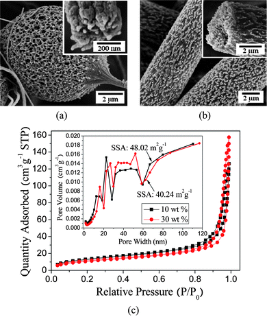
When the concentration of the PS (Mw = 208 000 g mol−1) solution was varied, remarkably a change was presented in the structural morphology of the electrospun fibers. The morphology of the fibrous mats transformed from beads-on-string fibers to uniform fibers (Fig. 5a and 5b) as the PS concentration increased from 10 to 30 wt% in THF:DMF with a weight ratio of 20:80. Increasing the PS concentration led to an increase in the viscosity of the PS solution and a decrease in solution conductivity.25 As a result, the instability and stretching effect of the fluid jet resulting from electrical forces was weakened in electrospinning which favored the formation of uniform fibers with larger diameters.28
 | ||
| Fig. 5
FE-SEM images of the PS (Mw = 208 000 g mol−1) fibers formed from (a) 10 wt% and (b) 30 wt% PS in THF:DMF with a weight ratio of 20:80. (c) Nitrogen adsorption–desorption isotherms and pore size distribution curves of the PS fibers formed with various concentrations. | ||
As can be seen from Fig. 5a, the bead about 6 μm in diameter is highly porous throughout and a cross-section of the string (300 nm) also showed the porous core morphology (inset of Fig. 5a). At 30 wt% PS, uniform fibers several microns in diameter were observed (Fig. 5b), and the surfaces of these fibers showed numerous grooves and protrusions (sea-island morphology) in the presence of nano/micro pores on the fiber surfaces (inset of Fig. 5b).
Fig. 5c shows the nitrogen adsorption–desorption isotherms and pore size distribution curves of the PS fibers formed with various concentrations. It can be found that the fibers have a similar pore size distribution in spite of the different polymer concentrations. It is interesting to note that the fibers formed from a 10 wt% PS solution show a lower quantity of N2 adsorption but a higher SSA of 48.02 m2 g−1 compared to the fibers formed from a 30 wt% PS solution with diameters of about 5 μm. This can be ascribed to the difference of the mesopores and macropores developed in electrospinning. The total pore volume and average pore width of fibers formed from 10 wt% PS solution are 0.187 m3 g−1 and 15.98 nm, respectively; whereas the fibers formed from 30 wt% PS solution have total pore volumes of 0.240 m3 g−1 and an average pore width of 22.96 nm. This result confirms that the porous structures play a key role in the SSA of porous PS fibers.
It is well known that electrospun fibers formed from a high polymer concentration show much better mechanical strength and integrity due to the formation of continuous long fibers.18,19 Moreover, electrospun PS fibrous mats are widely used as superhydrophobic surfaces as well as separation membranes for oil and water due to their oleophilic and hydrophobic properties.17–19,34 Just from the above inspiration, we choose the porous PS fibrous mats formed from a high concentration solution (30 wt%) as a sorbent to absorb the oil poured on water for oil spill cleanup.
Fig. 6a and 6b show the oleophilic and hydrophobic properties of PS fibrous mats formed from a 30 wt% solution and commercial PP non-woven fabric, respectively. Interestingly, water droplets placed on the PS fibrous mats showed a stable obtuse apparent water contact angle; whereas the oil droplets were immediately absorbed by the PS fibers (Fig. 6a). Although the commercial PP non-woven fabric also showed oleophilic and hydrophobic properties, it still can not be compared with porous PS fibrous mats due to their large fiber diameters (about 18 μm) and nonporous surface morphology (Fig. 6b and 6c).
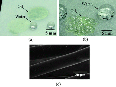 | ||
| Fig. 6 Water and oil droplets placed on the (a) porous PS fibrous mats, and (b) commercial PP non-woven fabric. (c) FE-SEM image of the PP fibers. | ||
Fig. 7 shows the different oil absorption behaviors of porous PS fibrous mats and commercial PP non-woven fabric as time went on. It can be seen that sunflower seed oil shows a much better affinity and wettability to the two kinds of sorbents which are immersed in oil almost completely after 5 min (Fig. 7c and 7d), while the sorbents floated on the motor oil film (Fig. 7a and 7b). This can be ascribed to the inherent properties of the oils listed in Table 1. After 30 min, all of the sorbents are wetted completely by the oils and immersed in oil films, indicating their good absorption ability for oils.
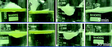 | ||
| Fig. 7 Absorption of (a and b) motor oil and sunflower seed oil (c and d) films on water by (a and c) porous PS fibrous mats and (b and d) PP fibers at different times: a to d for 5 min, and e to h for 30 min. | ||
Fig. 8 provides oils sorption capacities of the two kinds of sorbent. It can be clearly noted that porous PS fibrous mats show much larger oil absorption capacities than that of commercial PP non-woven fibres. The motor oil and sunflower seed oil absorption capacities of porous PS fibrous mats are 84.41 and 79.62 g g−1, respectively; which are nearly three times larger than that of commercial PP non-woven fabric for these two kinds of oils. The high oil absorption capacities of PS fibrous mats can be attributed to several factors, such as the highly porous structure of PS fibers, its much smaller fiber diameters compared to PP fibers, and much higher porosity of PS fibrous mats. It is imperative to point out that the selected PS fibrous mats formed from 30 wt% PS in THF:DMF with a weight ratio of 20:80 may not have the highest oil absorption capacity, but it shows a bight future for oil spill cleanups.
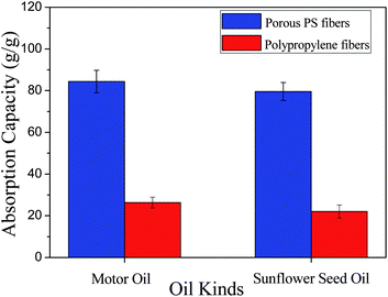 | ||
| Fig. 8 Maximum absorption capacities of the (a) porous PS fibrous mats, and (b) commercial PP nonwoven fibres for motor oil and sunflower seed oil. | ||
Conclusions
By regulating the molecular weights of a polymer with different sources, solvent compositions, as well as solution concentration in electrospinning, PS fibers with various micro- and nanostructures were fabricated directly from the solvent mixtures of THF:DMF with various weight ratios. The results indicated that both the SSA and surface morphology of the PS fibers could be controlled by tuning the solvent compositions and molecular weights of the PS. The porous structures of as-prepared fibers played a leading role in their SSA. The fibrous mats composed of highly porous PS fibers showed a good absorption ability for oils, which makes them a good candidate for oil spill cleanup to remove the oil contamination. Further more, we believe that the controllable manipulation of hierarchical structures within electrospun fibers will boost the performance in their applications and pave the way to industrialization
Acknowledgements
This work is supported by the National Natural Science Foundation of China (No. 50803009), the “111 Project” (No. 111-2-04 and B07024), the Shanghai Committee of Science and Technology (No. 10JC1400600), the National Basic Research Program of China (973 Program, 2011CB606103), the Innovation 50 Program of Shanghai Municipal Education Commission (11ZZ59), and the “Dawn” Program of the Shanghai Education Commission (10SG32).Notes and references
- B. Bhushan, Philos. Trans. R. Soc. London, Ser. A, 2009, 367, 1445 CrossRef CAS.
- B. Bhushan, Y. C. Jung and K. Koch, Philos. Trans. R. Soc. London, Ser. A, 2009, 367, 1631 CrossRef CAS.
- D. Li and Y. N. Xia, Adv. Mater., 2004, 16, 1151 CrossRef CAS.
- B. Ding, M. Wang, X. Wang, J. Yu and G. Sun, Mater. Today, 2010, 13, 16 CrossRef CAS.
- V. Thavasi, G. Singh and S. Ramakrishna, Energy Environ. Sci., 2008, 1, 205 CAS.
- D. H. Reneker and I. Chun, Nanotechnology, 1996, 7, 216 CrossRef CAS.
- J. Du and Y. L. Hsieh, Cellulose, 2009, 16, 247 CrossRef CAS.
- M. M. Hohman, M. Shin, G. Rutledge and M. P. Brenner, Phys. Fluids, 2001, 13, 2201 CrossRef CAS.
- P. K. Baumgarten, J. Colloid Interface Sci., 1971, 36, 71 CrossRef CAS.
- J. Doshi and D. H. Reneker, J. Electrost., 1995, 35, 151 CrossRef CAS.
- J. Y. Lin, B. Ding, J. Y. Yu, G. C. Wu, J. M. Yang and G. Sun, Int. J. Nonlinear Sci. Numer. Simul., 2010, 11, 523 CrossRef CAS.
- J. Lin, Y. Cai, X. Wang, B. Ding, J. Yu and M. Wang, Nanoscale, 2011, 3, 1258 RSC.
- H. Kokubo, B. Ding, T. Naka, H. Tsuchihira and S. Shiratori, Nanotechnology, 2007, 18, 165604 CrossRef.
- X. F. Wang, B. Ding, J. Y. Yu, Y. Si, S. B. Yang and G. Sun, Nanoscale, 2011, 3, 911 RSC.
- X. F. Wang, B. Ding, J. Yu, M. Wang and F. Pan, Nanotechnology, 2010, 21, 055502 CrossRef.
- T. Zhao, Z. Liu, K. Nakata, S. Nishimoto, T. Murakami, Y. Zhao, L. Jiang and A. Fujishima, J. Mater. Chem., 2010, 20, 5095 RSC.
- L. Jiang, Y. Zhao and J. Zhai, Angew. Chem., Int. Ed., 2004, 43, 4338 CrossRef CAS.
- Y. Miyauchi, B. Ding and S. Shiratori, Nanotechnology, 2006, 17, 5151 CrossRef CAS.
- X. H. Li, B. Ding, J. Y. Lin, J. Y. Yu and G. Sun, J. Phys. Chem. C, 2009, 113, 20452 CAS.
- L. Wannatong, A. Sirivat and P. Supaphol, Polym. Int., 2004, 53, 1851 CrossRef CAS.
- K. H. Lee, H. Y. Kim, H. J. Bang, Y. H. Jung and S. G. Lee, Polymer, 2003, 44, 4029 CrossRef CAS.
- S. Megelski, J. S. Stephens, D. B. Chase and J. F. Rabolt, Macromolecules, 2002, 35, 8456 CrossRef CAS.
- C. L. Casper, J. S. Stephens, N. G. Tassi, D. B. Chase and J. F. Rabolt, Macromolecules, 2004, 37, 573 CrossRef CAS.
- S. Koombhongse, W. Liu and D. H. Reneker, J. Polym. Sci., Part B: Polym. Phys., 2001, 39, 2598 CrossRef CAS.
- J. Y. Lin, B. Ding, J. Y. Yu and Y. Hsieh, ACS Appl. Mater. Interfaces, 2010, 2, 521 CAS.
- C. L. Pai, M. C. Boyce and G. C. Rutledge, Macromolecules, 2009, 42, 2102 CrossRef CAS.
- P. Dayal, J. Liu, S. Kumar and T. Kyu, Macromolecules, 2007, 40, 7689 CrossRef CAS.
- P. Dayal and T. Kyu, J. Appl. Phys., 2006, 100 Search PubMed.
- L. F. Wang, C. L. Pai, M. C. Boyce and G. C. Rutledge, Appl. Phys. Lett., 2009, 94, 151916 CrossRef.
- J. Du and Y. L. Hsieh, Nanotechnology, 2008, 19, 125707 CrossRef.
- K. Sing, D. Everett, R. Haul, L. Moscou, R. Pierotti, J. Rouquerol and T. Siemieniewska, Pure Appl. Chem., 1985, 57, 603 CrossRef CAS.
- C. Kim, Y. I. Jeong, B. T. Ngoc, K. S. Yang, M. Kojima, Y. A. Kim, M. Endo and J. W. Lee, Small, 2007, 3, 91 CrossRef CAS.
- M. Bognitzki, W. Czado, T. Frese, A. Schaper, M. Hellwig, M. Steinhart, A. Greiner and J. H. Wendorff, Adv. Mater., 2001, 13, 70 CrossRef CAS.
- C. W. Tu, C. H. Tsai, C. F. Wang, S. W. Kuo and F. C. Chang, Macromol. Rapid Commun., 2007, 28, 2262 CrossRef CAS.
| This journal is © The Royal Society of Chemistry 2012 |