An electrokinetically tunable optofluidic bi-concave lens†
Haiwang
Li
a,
Chaolong
Song
b,
Trung
Dung Luong
a,
Nam-Trung
Nguyen
*a and
Teck
Neng Wong
a
aSchool of Mechanical and Aerospace Engineering, Nanyang Technological University, 50 Nanyang, Avenue, Singapore 639798. E-mail: mntnguyen@ntu.edu.sg
bSchool of Physical and Mathematical Sciences, Nanyang Technological University, 21 Nanyang Link, Singapore 637371
First published on 24th May 2012
Abstract
This paper numerically and experimentally investigates and demonstrates the design of an optofluidic in-plane bi-concave lens to perform both light focusing and diverging using the combined effect of pressure driven flow and electro-osmosis. The concave lens is formed in a rectangular chamber with a liquid core-liquid cladding (L2) configuration. Under constant flow rates, the performance of the lens can be controlled by an external electric field. The lens consists of a core stream (conducting fluid), cladding streams (non-conducing fluids), and auxiliary cladding streams (conducting fluids). In the focusing mode, the auxiliary cladding stream is introduced to sandwich the biconcave lens to prevent light rays from scattering at the rough chamber wall. In the diverging mode, the auxiliary cladding liquid has a new role as the low refractive-index cladding of the lens. In the experiments, the test devices were fabricated in polydimethylsiloxane (PDMS) using the standard soft lithography technique. Ethanol, cinnamaldehyde, and a mixture of 73.5% ethylene glycol and 26.5% ethanol work as the core stream, cladding streams and auxiliary cladding streams. In the numerical simulation, the electric force acts as a body force. The governing equations are solved by a finite volume method on a Cartesian fixed staggered grid. The evolution of the interface was captured by the level set method. The results show that the focal length in the focusing mode and the divergent angle of the light beam in the diverging mode can be tuned by adjusting the external electric field at fixed flow rates. The numerical results have a reasonable agreement with the experimental results.
Introduction
One of the most popular micro optofluidic applications is the liquid core-liquid cladding (L2) micro-lens, which improves the portability of optical components and potentially makes lab-on-a-chip systems cost-effective.1–4 Prior to optofluidic L2 micro-lenses, solid-interface lenses were integrated into a microfluidic network to improve the light properties.5,6 Compared to solid-interface lenses, micro optofluidic L2 lenses have a number of advantages, such as smooth interfaces, tuneable focal length, and a simple fabrication process.7–9 Following the concept of L2 micro-lenses, different types of optofluidic lenses have been developed.1,10–19 These lenses can dynamically manipulate a light beam introduced from an optical fibre. Moreover, their L2 configuration has an atomically smooth interface, in contrast to the rough interface of solid-base lenses. Nguyen20 recently reviewed the different concepts of implementing micro optofluidic lenses.Currently, most L2 lenses can only focus light along the optical axis. The single function of these micro-lenses cannot satisfy the requirement of fluorescence excitation and detection. Mao et al.19 designed a gradient refractive-index lens to swing a focused light beam, based on the diffusion interface, between two miscible fluids. Song et al.2 reported a liquid-core liquid-cladding prism to continuously deflect light. Xiong et al.9 presented another prism to deflect light using only two laminar flow streams of different refractive indices. These works provided different ways of modifying the in-plane light, by which the area out of the optical axis can also be selectively illuminated, thus exciting the local fluorescent sample. Song et al.8 integrated the focusing and diverging function into a single bi-concave lens, where the focal length or the divergent angle of the light beam can be tuned by adjusting the flow rate ratio between core and cladding streams.
The light properties of focused length, location of light beam or divergent degree depend on the interfacial shape between the streams. The majority of previous micro optofluidic lenses tune the interfacial shape by adjusting flow rates.2,3,8,11,12,19 The results showed that the relationship between the interfacial shape and the flow rate ratio of the core stream and the cladding streams is a complex parabola.8 In order to achieve the ideal optical performance, the flow rate ratio has to be manually adjusted. Electro-osmosis is another popular actuating method in microfluidics for the control of the interfacial shape and location.21–25 When the electric field is used to adjust the interfacial shape, a direct relationship between the interfacial shape and the electric field can be established.4,26,27
This paper presents the design and demonstration of an optofluidic bi-concave lens that can tune a light beam from focused to divergent using the combined effect of pressure and electro-osmosis. The functions are achieved by adjusting the applied external electric field under fixed flow rates. This lens consists of a core stream, cladding streams and auxiliary cladding streams. These streams have various roles in both the focusing mode and the diverging mode. Fig. 1(a) schematically describes the focusing mode of the lens. In this mode, the core stream is a conducting fluid with a low refractive index, and the cladding streams are non-conducting fluids, each with a high refractive index. The flow rates of the core stream and cladding stream are kept constant throughout practical operation. The external electric field is added to the core stream. Following the concept reported by Song et al.,8 an auxiliary cladding stream with a very low flow rate and a refractive index matching that of PDMS can prevent the light beam from scattering. Although no external electric field is added to the auxiliary cladding stream, the auxiliary cladding streams are electrically conducting in order to tune the lens from focusing mode to diverging mode conveniently. The effect of the auxiliary cladding stream is negligible due to the low flow rate and refractive index. The light emitted from the optical fibre can be highly focused and the focal length can be tuned by adjusting the electric field applied to the conducting core stream. The diverging mode is described in Fig. 1(b). In the diverging mode, the roles of the streams are changed. Table 1 indicates these changes. The core stream in the focusing mode is blocked, the cladding streams in the focusing mode become the core stream, and the auxiliary cladding streams act as cladding streams. In the diverging mode, the core stream is non-conducting and the cladding streams are conducting, thus, the external electric field is applied to the cladding stream. The divergence of the light beam is achieved via the higher refractive index of the core stream and the tuneable lens interface. The expansion of the light beam can be adjusted by the external electric field.
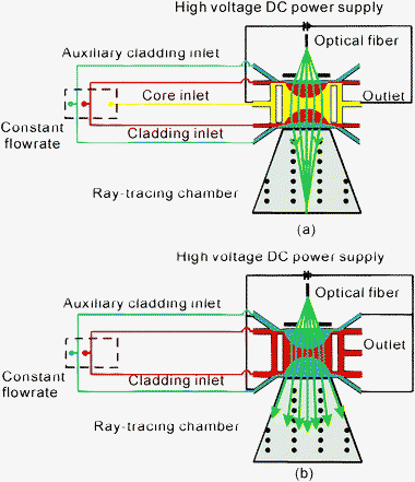 | ||
| Fig. 1 Schematics: (a) bi-concave lens in the focusing mode. The light beam in the ray-tracing chamber propagates through the bi-concave lens in the focusing mode. The liquids for the core, cladding, and auxiliary cladding streams are ethanol, cinnamaldehyde, and the mixture of 73.5% ethylene glycol and 26.5% ethanol, respectively. The voltage applied to the core stream is −5000 V. (b) Bi-concave lens in the diverging mode. The light beam in the ray-tracing chamber propagates through the bi-concave lens in the diverging mode. The liquids for the core and cladding streams are cinnamaldehyde, and the mixture of 73.5% ethylene glycol and 26.5% ethanol, respectively. | ||
| Liquids | Focusing | Diverging |
|---|---|---|
| Ethanol | Core stream | — |
| Cinnamaldehyde | Cladding stream | Core stream |
| Mixture of 73.5% ethylene glycol and 26.5% ethanol | Auxiliary cladding stream | Cladding stream |
Compared to the micro optofluidic lenses previously reported in the literature, our lens combines the functions of both focusing and diverging in a single design. In addition, the width of the light beam can be tuned across a larger range.
Numerical simulation
Physical model
The configuration of the devices is illustrated in Fig. 1. The rectangular chamber for forming the optofluidic lens measures 1 × 1 mm. The device includes five inlets, a core inlet, two pairs of cladding inlets and three outlets. The widths of the inlets and outlets are 50 μm. Light is emitted from an optical fiber aligned by a pre-fabricated guide channel with a width of 130 μm. The distance between the center of the rectangular chamber and the tip of the fiber is 4 mm. In order to fix the angle of incoming light and filter the noise, an aperture with a size of 400 μm is formed by filling ink into the two aperture channels. The propagation of light rays is visualized by a ray-tracing chamber which is placed behind the rectangular lens chamber and filled with fluorescence dye. The whole device has a uniform thickness of 120 μm. Fig. 2(a) shows the computational domain of the numerical model. The domain includes the rectangular chamber, the inlets and the outlets.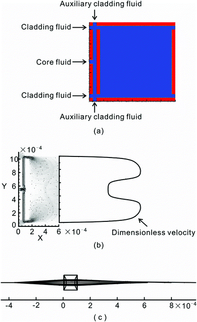 | ||
| Fig. 2 Numerical model of the lens: (a) domain calculated in numerical simulation, (b) velocity profile in the rectangular chamber for the diverging mode. The flow rates of the core and cladding streams are fixed at same value of 0.5 ml h−1. The voltage applied to the cladding stream is 5000 V. (c) Numerical ray-tracing results. The flow rates of the core and cladding streams are fixed at the same value of 0.5 ml h−1. The voltage applied to the core stream is −3000 V. | ||
Governing equations
The electric field (E) in the conducting fluid can be determined by the gradient of the electrical scalar potential φ:| E = −∇φ | (1) |
where ∇ is the del operator. In a dielectric medium, the electrical scalar potential φ is governed by:
| ∇ (ε∇φ) = 0 | (2) |
 | (3) |
The multi-phase microfluidic system can be described by the Navier–Stokes equation coupled with the electric force.
| ∇·(ρivv)−∇·[μi(∇v + ∇vT)] = −∇p + Eρe | (4) |
where ρi is the initial fluid density, v is the flow velocity, μi is the dynamic viscosity, and p is the pressure. Gravity is neglected in this model. An incompressible media is assumed:
| ∇·(ρiv) = 0 | (5) |
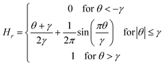
The jumps of the properties near the interface were smoothed with Heaviside function over the whole computational domain 28
 | (6) |
 | (7) |
Since the thickness of the microchannel (120 μm) is small compared to the other dimension (1 mm), the depth average method30 was used in this work to reduce the three-dimensional model to a two-dimensional model.
Level set method
The level-set method is used to model the interfaces between different fluids.29 A level set function θ is introduced over the whole computational domain to describe the shortest normal distance from the interface. The interface is represented by θ = 0. The signs “+” and “−” are used to distinguish the two liquid phases. The level-set function is defined as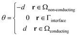 | (8) |
| v·∇θ = 0 | (9) |
A reinitialization procedure is employed to maintain the level set function as a signed distance function to the interface with some degree of accuracy
 | (10) |
![[t with combining tilde]](https://www.rsc.org/images/entities/i_char_0074_0303.gif) is a pseudo time for the variable ς. The steady state solution of ς is always a level-set function. The initial condition of eqn (10) is
is a pseudo time for the variable ς. The steady state solution of ς is always a level-set function. The initial condition of eqn (10) is| ς(r,0) = θ(r) | (11) |
For numerical purposes, it is useful to smooth the signed function as
 | (12) |
Boundary conditions
For an electric field, the voltages (Vinlet and Voutlet) are added to the inlets and outlets to calculate the electrical potential distribution. Vinlet and Voutlet are the voltages set by a high voltage DC power supply. For the pressure gradient, the average velocity at the inlet is ui = qi/wh, where qi is the volumetric flow rate provided by a syringe pump in the corresponding experiment and w and h are the channel width and height, respectively. Outflow boundary conditions are used for the outlets. The initial level-set function is set to an assumed shape and evolved under eqn (9) to its steady state shape.Numerical methods
The governing equations of the Navier–Stokes equation eqn (4), the continuum equation eqn (5), and the electrical potential eqn (2) are solved on the Cartesian staggered grid by a finite volume method. The SIMPLER algorithm is used to couple velocity and pressure.31 The power law is applied to predict the combined convection-diffusion effect. The level set eqn (9) and the reinitialization eqn (10) are solved by constructing high-order weighted essentially non-oscillatory (WENO) schemes with local Lax-Friedrichs flux32 and Godunov flux,33 respectively, and advected by the total variation diminishing (TVD) Runge–Kutta method.34 The solution procedure can be summarized as follows:(a) Guess the locations of the interfaces,
(b) Calculate the value of θ for all nodes for the interface,
(c) Calculate the properties for all nodes using eqn (6) and (7),
(d) Solve the distribution of electric potentials using eqn (1) and (2),
(e) Solve the continuity and momentum equations given by eqn (4) and (5) according the electric field and boundary conditions,
(f) Calculate the value of θ using eqn (9) according to the velocity distribution from step (5),
(g) Calculate the value of ζ according to eqn (10) and the solution of step (6),
(h) Set θ(r) = ζ(r) and
(i) Repeat steps (3)–(8) until the solution converges.
Fabrication and experimental setup
A soft lithography technique was used to fabricate the microchannel in polydimethylsiloxane (PDMS).35 The mask was printed on a transparency film with a resolution of 8000 dpi. A 120-μm thick SU-8 layer was first spin-coated on a silicon wafer after being soft baked (65 °C, 10 min) and hard baked (95 °C, 45 min); the SU-8 layer was then exposed and developed. PDMS (Dow corning corporation, USA) was mixed from the two components (base and curing agent) with a weight ratio of 10![[thin space (1/6-em)]](https://www.rsc.org/images/entities/char_2009.gif) :1. The mixed PDMS free of bubbles was poured onto the SU-8 mould. The PDMS part was then kept at room temperature for 36 h to cure. Subsequently, the cured PDMS was peeled off from the master mould. The fluidic ports with a diameter of 0.5 mm were punched into the PDMS part. Finally, another cured flat PDMS slab and the PDMS with the microchannel were treated on the surface using oxygen plasma and bonded together. With this technology, a channel height of 120 μm can be achieved for the microfluidic network.
:1. The mixed PDMS free of bubbles was poured onto the SU-8 mould. The PDMS part was then kept at room temperature for 36 h to cure. Subsequently, the cured PDMS was peeled off from the master mould. The fluidic ports with a diameter of 0.5 mm were punched into the PDMS part. Finally, another cured flat PDMS slab and the PDMS with the microchannel were treated on the surface using oxygen plasma and bonded together. With this technology, a channel height of 120 μm can be achieved for the microfluidic network.
In the experiments, all liquids were kept in 10 ml glass syringes (10 ml gastight, Hamilton). The syringes were driven by syringe pumps (KDS230, KD Scientific Inc, USA, 0.2 μl h−1 to 500 l h−1, accuracy of 0.5%) to deliver the fixed flow rates. The greyscale images were captured using a sensitive CCD camera (HiSense MKII) attached to the microscope. A digital camera (DCRDVD803E, SONY) was used to record the colour images. Laser light (200 mW, 532 nm) was coupled into a multimode optical fibre (AFS105/125Y, THORLABS Inc) with a numerical aperture NA = 0.22. The optical fiber was inserted into a pre-fabricated microchannel with a width of 130 mm to act as a point light source. Stainless steel tips (EFD, 5123PC-B, USA) were used to connect the inlet port and hard Teflon tubing. The inner and outer surfaces of the tips were covered with polytetrafluoroethylene. Platinum wires (Sigma-Aldrich, 0.1 mm diameter) were used as electrodes. The electric fields were provided by a high voltage DC power supply (Model PS350, Stanford Research System, Inc).
In the focusing mode, the core stream is ethanol (n = 1.36; μ = 1.2 × 10⁻³ N s m−2). In order to add the electric field to ethanol, NaCl was diluted in ethanol with a concentration of 7 × 10⁻⁴ M. The cladding stream is cinnamaldehyde (n = 1.62; μ = 5.7 × 10⁻³ N s m−2). The auxiliary cladding stream is a mixture of 73.5% ethylene glycol and 26.5% ethanol (n = 1.412; μ = 9.8 × 10⁻³ N s m−2). This mixture has the same refractive index as PDMS (n = 1.412). Similar to ethanol, NaCl was diluted in ethanol with a concentration of 7 × 10⁻⁴ M. During the experiments, the flow rates of the core stream and cladding stream were fixed at 0.5 ml h−1 and the flow rate of the auxiliary cladding stream was fixed at 0.05 ml h−1. To tune the lens curvature, an electric field was applied to the core stream. In the diverging mode, the core flow was stopped to allow cinnamaldehyde from the cladding inlets to become the new core stream, therefore changing the role of the auxiliary cladding liquid from light-scattering prevention to providing an alternative refractive index for the refraction of the light rays. In this mode, the flow rates of two streams were fixed at 0.5 ml h−1, and an electric field was added to the new cladding stream. A mixture of 73.5% ethylene glycol and 26.5% ethanol (n = 1.412) with fluorescence dye Rhodamine B (Sigma Aldrich, excitation wavelength 540 nm, emission wavelength 625 nm, 1 g L−1) was pumped into the ray-tracing chamber to visualize the light rays refracted by the concave lens.
Results and discussion
Focusing mode
Fig. 3 shows typical images of the lens by adjusting the electric field applied to the core stream under the fixed flow rates of 0.5 ml h−1. The zeta potential of PDMS with NaCl solution is about −85 mV.36 The surface charge of the PDMS wall is negative and the charge of the ion within the electrical double layer (EDL) is positive.37 Under a positive electric field, the positively charged ion moves and drags the core liquid flow along the electric field. As a result, the core stream flows faster. Under the fixed pressure-driven flow rate, the core stream with the higher velocity will occupy a smaller part of the channel. The cladding fluid will occupy a larger part of the channel and thus, the curvature of the interface will increase. At the same time, if a negative electric field is applied to the core stream, the positively charged ion moves and drags the core liquid flow opposing the pressure-driven flow. The core stream becomes slower and occupies a larger part of the channel. The cladding fluid will occupy a smaller part of the channel, and the curvature of the interface will decrease. Fig. 3 shows that the curvature of the interface at −5000 V is smaller than that at 0 V.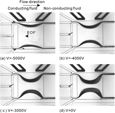 | ||
| Fig. 3 The interfacial shape of the micro optofluidic bi-concave lens in focusing mode at different electric fields and fixed flow rates. The flow rates of the core stream and the cladding stream are all 0.5 ml h−1: (a) −5000 V; (b) −4000 V; (c) −3000 V; (d) 0 V. | ||
The optical performance of the optofluidic concave lens in the focusing mode was carried out experimentally and numerically using the ray-tracing method. Fig. 4 shows the experimental ray-tracing results for the focusing mode under various electric fields in the cladding streams and fixed flow rates of core fluid and cladding fluids. In the experiment, the fluorescence dye in the ray-tracing chamber is excited by the green laser from a fibre with a wavelength of 532 nm and recorded as a grayscale image. In the numerical simulation, a custom Matlab program based on Snell's law8 was implemented to trace the ray. Due to the refractive index of the core liquid (ethanol, n = 1.36) being lower than that of the cladding liquid (cinnamaldehyde, n = 1.62), the optofluidic concave lens possesses a light focusing effect. In order to measure the focal length of the optofluidic concave lens, the grayscale images of the light rays in the ray-tracing chamber were captured. The flow rates of the cladding stream and the core stream are fixed at 0.5 ml h−1.
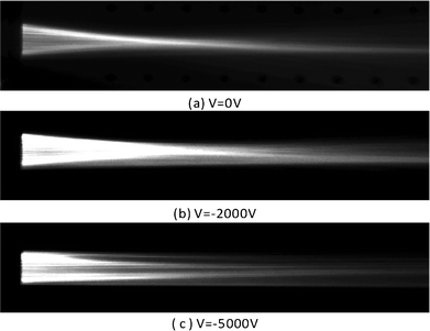 | ||
| Fig. 4 The experimental ray-tracing results for focusing mode under various electric fields in the cladding streams and fixed flow rates of core fluid and cladding fluids: (a) 0 V; (b) −2000 V; (c) −5000 V. | ||
Fig. 5(a) shows the manipulation of the lens interface by adjusting the electric field added to the core stream under the fixed flow rates for the focusing mode of the optofluidic bi-concave lens. The error bars in Fig. 5 indicate the effect of flow fluctuation inside the lens chamber. In the experiments, the flow rates of the core stream and the cladding streams were fixed at 0.5 ml h−1, and the auxiliary cladding stream was fixed at 0.05 ml h−1. The voltage added to the core stream was varied from −5000 to 1000 V. When the voltage was 0 V, the core stream wass purely pressure driven. Under the same flow rates, the cladding stream (μ = 5.7 × 10⁻³ N s m−2) with high viscosity occupied a large part. The curvature of the interface between the core and the cladding stream was approximately 1.96 mm−1. If a negative electric field is applied to the core stream, the core stream flows slower and occupies a larger part of the channel. The curvature of the interface decreases. The effect of electro-osmosis becomes stronger with the increasing magnitude of the negative electric field. The curvature of the interface decreases with the increasing field magnitude. For the smooth curved interface, the curvature of the interface can be calculated according the radius of the interface using the relationship of κ = 1/R where R is the radius of interface. The curvature reduces to 1.62 mm−1 when V = 5000 V. A positive electric field drives the core stream flowing faster. The smaller core stream increases the curvature of the interface. The sensitivity of electro-osmosis becomes low under a highly positive electric field.
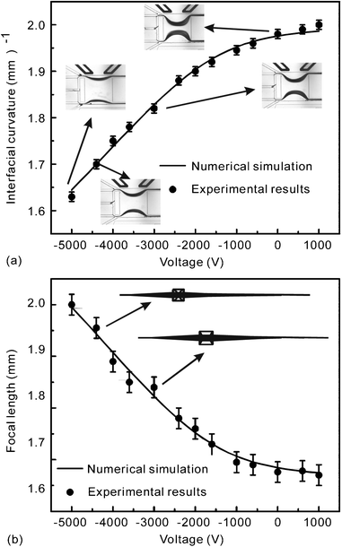 | ||
| Fig. 5 Focusing mode: (a) relationship between the external electric filed and the curvature of the interface under fixed flow rates in the focusing mode of the optofluidic bi-concave lens; (b) relationship between the external electric filed and the focal length under fixed flow rates in the focusing mode of the optofluidic bi-concave lens. The flow rates of core stream and cladding streams are fixed at 0.5 ml h−1. | ||
Fig. 5(b) shows the numerical and experimental focal length over a range of voltages with a fixed flow rate of 0.5 ml h−1. The intersection position of the rays and the optical axis is regarded here as the focal point. The focal point is calculated according the angular aperture of a light-ray in the image space. The results show that a negative electric field increases the focal length while a positive electric field decreases the focal length. Fig. 5 indicates that the numerical results have a good agreement with the experimental results.
Diverging mode
The diverging mode can be easily switched from the focusing mode by stopping the liquid (ethanol) of the core inlet. As a result, the previous cladding liquid (cinnamaldehyde) in the focusing mode will converge in the rectangular chamber and become the core stream. The auxiliary cladding liquid (mixture of 73.5% ethylene glycol and 26.5% ethanol) not only prevents light-scattering but also refracts light rays. The flow rates of the new core stream and the new cladding stream are fixed at 0.5 ml h−1. An electric field is applied to the new cladding streams.Fig. 6 shows a series of lens interfaces on adjustment of the electric field applied to the cladding streams under a fixed flow rate of 0.5 ml h−1. Similar to the previous case of focusing, under a positive electric field, the positively charged ions within the cladding stream move and drag the cladding stream flow along the electric field. Thus, the cladding stream flows faster. Under the fixed flow rate, the cladding stream with the higher velocity will occupy a smaller part of channel. The core stream occupies a larger part of the channel and the curvature of the interface decreases. If a negative electric field is added to the cladding streams, the positive ions move and drag the cladding liquid to flow against the pressure. As a result, the cladding stream flows slower. Under the fixed flow rate, the cladding stream with the slower velocity occupies a larger part of the channel. The core fluid occupies a smaller part of the channel and the curvature of the interface increases. Fig. 6 clearly shows that the curvature of the interface at 4500 V is smaller than the curvature at 0 V.
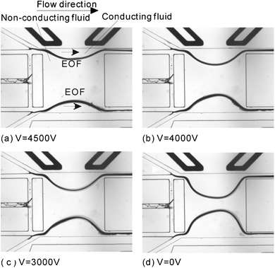 | ||
| Fig. 6 The interfacial shape of the optofluidic bi-concave lens in diverging mode based on the different applied voltages and fixed flow rates. The flow rates of core stream and cladding stream are all 0.5 ml h−1: (a) 4500 V; (b) 4000 V; (c) 3000 V; (d) 0 V. | ||
In the diverging mode, the light beam from the optical fibre will expand because the refractive index of the core liquid is higher than that of the cladding stream. The similar experimental and numerical methods of ray-tracing are used in the focusing mode to investigate the optical performance of the diverging lens. The rays with an angular aperture in the image space were extracted from the recorded images. The divergent angle is the angle of the outer rays. Fig. 7 shows the experimental results with flow rates fixed at 0.5 ml h−1. The results show that the divergent angle can be altered using an electric field with a fixed flow rate. If the electric field is 0 V, the divergent angle is approximately 37.5°, Fig. 7(a). The divergent angle reduces to approximately 28° if the applied voltage increases to 5000 V, Fig. 7(b).
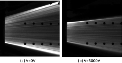 | ||
| Fig. 7 The experimental ray-tracing results for the diverging mode with an electric field in the cladding stream and a fixed flow rate of core fluid and cladding fluids: (a) 0 V; (b) 5000 V. | ||
Fig. 8(a) shows the relationship between the electric field and the curvature of the interface under fixed flow rates for the diverging mode. In the experiments, the flow rates of the core stream and the cladding streams are fixed at 0.5 ml h−1. The voltage applied on the cladding stream changes from −1000 to 5000 V. If the voltage is 0 V, the core and cladding streams are purely pressure driven. The curvature of the interface between the core and the cladding stream is approximately 1.9 mm−1. When a negative electric field is applied to the cladding stream, the stream becomes slower and occupies a larger part of the channel. Thus, the curvature of the interface increases. For instance, the curvature is 1.96 mm−1 at −1000 V. The curvature of the interface increases with the increasing negative electric field. In contrast, the positive electric field drives the cladding stream faster and decreases the curvature of the interface. For instance, the curvature is only about 1.57 mm−1 at 5000 V.
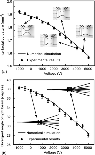 | ||
| Fig. 8 Diverging mode: (a) relationship between the external electric filed and the curvature of the interface under fixed flow rates in the diverging mode of the optofluidic bi-concave lens; (b) relationship between the external electric filed and the focal length under fixed flow rates in the diverging mode of the optofluidic bi-concave lens. The flow rates of core stream and cladding streams are fixed at 0.5 ml h−1. | ||
Fig. 8(b) shows a comparison between the experimental results and the numerical simulation of the divergent angle. The results were obtained when the flow rates of the core stream and the cladding streams were fixed at 0.5 ml h−1 and the voltage along the cladding stream changed from −1000 to 5000 V. If the positive electric field is very high, the curvature of the interface is small. The impact of the interface on the refraction of the light ray is small. Owing to the aperture, the opening angle of the light beam originating from the fibre is approximately 6°. The divergent angle then expands to 28° when the voltage reaches its highest value of 5000 V. The divergent angle increases monotonously as the positive electric field decreases, and reaches 38° at 1000 V.
The radiant flux and the size of the illumination area can be controlled using the lens in diverging mode by adjusting the electric field. Moreover, this tuneable diverging lens may be useful for the correction of spherical aberration in optofluidic lens systems.
Conclusions
This paper reports the design and characterization of an optofluidic bi-concave lens, which can perform both light focusing and diverging. The optofluidic bi-concave lens can easily switch from focusing mode to diverging mode. In focusing mode, the auxiliary cladding stream is introduced to sandwich the biconcave lens to prevent light rays from scattering at the rough chamber wall. The core stream is a conducting fluid, to which an external voltage is applied. In the diverging mode, the core stream in the focusing mode is blocked, and the auxiliary cladding liquid not only avoids light-scatting but also becomes the low refractive-index cladding of the lens. The cladding streams of the focusing mode can join together in the chamber and become the core stream of the diverging mode. A voltage is applied to the cladding stream to control the lens curvature. In the numerical simulation, the electric force acts as a body force. The governing equations are solved using the finite volume method on a Cartesian fixed staggered grid. The level set method was used to capture the interface. The results showed that the characterization of an optofluidic bi-concave lens can be controlled using an external electric field under fixed flow rates. In the focusing mode, the focal length can be adjusted electrically. A positive electric field in the core stream gives rise to a shorter focal length. In contrast, a negative electric field results in a longer focal length. In the diverging mode, light can be extended to a larger divergence if a negative electric field is added to the cladding streams.Acknowledgements
T.N. Wong, N.T Nguyen and H. Li gratefully acknowledge research support from the Singapore Ministry of Education Academic Research Fund Tier 2 research grant MOE2011-T2-1-036.References
- L. K. Chin, Y. C. Seow, C. S. Lim and A. Q. Liu, presented in part at the μTAS2008(12th International Conference on Miniaturized Systems for Chemistry and Life Sciences, San Diego, California, USA, 2008 Search PubMed.
- C. Song, N. T. Nguyen, A. K. Asundi and S. H. Tan, Opt. Lett., 2010, 35, 327–329 CrossRef.
- C. Song, N. T. Nguyen, S. H. Tan and A. K. Asundi, Microfluidics and Nanofluidics, 2010, 1–8 Search PubMed.
- H. Li, T. N. Wong and N. T. Nguyen, Microfluid. Nanofluid., 2011, 10, 1033–1043 CrossRef CAS.
- S. Camou, H. Fujita and T. Fujii, Lab Chip, 2003, 3, 40–45 RSC.
- J. Wenger, D. Gerard, H. Aouani and H. Rigneault, Anal. Chem., 2008, 80, 6800–6804 CrossRef CAS.
- D. B. Wolfe, R. S. Conroy, P. Garstecki, B. T. Mayers, M. A. Fischbach, K. E. Paul, M. Prentiss and G. M. Whitesides, Proc. Natl. Acad. Sci. U. S. A., 2004, 101, 12434–12438 CrossRef CAS.
- C. Song, N. T. Nguyen, Y. F. Yap, T. D. Luong and A. K. Asundi, Microfluid. Nanofluid., 2011, 10, 671–678 CrossRef.
- S. Xiong, A. Q. Liu, L. K. Chin and Y. Yang, Lab Chip, 2011, 11, 1864–1869 RSC.
- D. C. Dino, Lab Chip, 2009, 9, 3038–3046 RSC.
- M. Rosenauer and M. J. Vellekoop, Lab Chip, 2009, 9, 1040–1042 RSC.
- J. Shi, Z. Stratton, S. C. S. Lin, H. Huang and T. J. Huang, Microfluid. Nanofluid., 2010, 9, 313–318 CrossRef CAS.
- S. K. Y. Tang, C. A. Stan and G. M. Whitesides, Lab Chip, 2008, 8, 395–401 RSC.
- C. Song, N. T. Nguyen, S. H. Tan and A. K. Asundi, Lab Chip, 2009, 9, 1178–1184 RSC.
- X. Mao, J. R. Waldeisen, B. K. Juluri and T. J. Huang, Lab Chip, 2007, 7, 1303–1308 RSC.
- L. Dong and H. Jiang, J. Microelectromech. Syst., 2008, 17, 381–392 CrossRef CAS.
- X. Mao, B. K. Juluri, S. C. Lin, J. Shi, M. I. Lapsley and T. J. Huang, LEOS Summer Topical Meeting, 2008, 201–202 Search PubMed.
- Y. Liu, X. Zeng, L. Dong and H. Jiang, Progress in Biomedical Optics and Imaging - Proceedings of SPIE, 2009, 71670L, 1–10 Search PubMed.
- X. Mao, S. C. S. Lin, M. I. Lapsley, J. Shi, B. K. Juluri and T. J. Huang, Lab Chip, 2009, 9, 2050–2058 RSC.
- N. T. Nguyen, Biomicrofluidics, 2010, 031501-1–031501-15 Search PubMed.
- A. Manz, C. S. Effenhauser, N. Burggraf, D. J. Harrison, K. Seiler and K. Fluri, J. Micromech. Microeng., 1994, 4, 257–265 CrossRef CAS.
- L. Ren, C. Escobedo and D. Li, J. Colloid Interface Sci., 2001, 242, 264–271 CrossRef CAS.
- D. Sinton and D. Li, Colloids Surf., A, 2003, 222, 273–283 CrossRef CAS.
- D. Kohlheyer, G. A. J. Besselink, R. G. H. Lammertink, S. Schlautmann, S. Unnikrishnan and R. B. M. Schasfoort, Microfluid. Nanofluid., 2005, 1, 242–248 CrossRef CAS.
- H. Li, T. N. Wong and N. T. Nguyen, Microfluid. Nanofluid., 2009, 1–9 Search PubMed.
- H. Li, T. N. Wong and N. T. Nguyen, Microfluid. Nanofluid., 2011, 10, 965–976 CrossRef CAS.
- H. Li, T. N. Wong, N. T. Nguyen and J. C. Chai, Int. J. Heat Mass Transfer, 2012, 55, 2647–2655 CrossRef CAS.
- Y. F. Yap, J. C. Chai, T. N. Wong, K. C. Toh and H. Y. Zhang, Numer. Heat Transfer, Part B, 2006, 50, 455–472 CrossRef.
- R. F. Stanley Osher, Level set method and dynamic implicity surfaces, Springer, New York, 2003 Search PubMed.
- Y. C. Lam, X. Chen and C. Yang, Microfluid. Nanofluid., 2005, 1, 218–226 CrossRef.
- S.V. Patankar, Numerical Heat Transfer and Fluid Flow, Hemisphere Pub. Corp, Washington, 1980 Search PubMed.
- C. W. Shu and S. Oshert, J. Comput. Phys., 1989, 83, 32–78 CrossRef.
- G. S. Jiang and D. Peng, SIAM J. Sci. Comput., 2000, 21, 2126–2143 CrossRef.
- G. S. Jiang and C. W. Shu, J. Comput. Phys., 1996, 126, 202–228 CrossRef.
- N. T. Nguyen, Fundamentals and applications of microfluidics, Artech House, Boston, 2006 Search PubMed.
- J. S. H. Lee and D. Li, Microfluid. Nanofluid., 2006, 2, 361–365 CrossRef CAS.
- R. J. Hunter, Zeta potential in colloid science Principles and applications, Harcourt Brace Jovanovich, Sydney, 1981 Search PubMed.
Footnote |
| † Published as part of a themed issue on optofluidics. |
| This journal is © The Royal Society of Chemistry 2012 |