Robust PEDOT films by covalent bonding to substrates using in tandem sol–gel, surface initiated free-radical and redox polymerization†
Anand G.
Sadekar
,
Dhairyashil
Mohite
,
Sudhir
Mulik
,
Naveen
Chandrasekaran
,
Chariklia
Sotiriou-Leventis
* and
Nicholas
Leventis
*
Department of Chemistry, Missouri University of Science and Technology, Rolla, MO 65409, USA. E-mail: leventis@mst.edu; cslevent@mst.edu
First published on 28th September 2011
Abstract
Poly(3,4-ethylenedioxythiophene), PEDOT, films are used as antistatic coatings on electrically insulating substrates such as plastic and glass. A novel method for the synthesis of conducting PEDOT films on insulators relies on sol–gel chemistry to attach a di-Si(OEt)3 functionalized free radical initiator (AIBN) on oxidized surfaces, followed by: (a) attachment of 3,4-(vinylenedioxy)thiophene (VDOT: an analogue to EDOT susceptible to radical addition through its vinylenedioxy group); and, (b) oxidative (with FeCl3) co-polymerization of surface-confined VDOT with 3,4-ethylenedioxythiophene (EDOT). In conjunction with classical photolithography, the method yields thin (∼150 nm) yet dense, pinhole-free (confirmed electrochemically), hard (>6H), extremely adhesive (5B), patterned, highly conducting (52 mho cm−1) films. The process is applied mainly on glass but it works equally well on oxidized metal surfaces (aluminum, steel, Pt). Control studies related to “grafting from” with surface-confined AIBN were conducted by growing inexpensive poly(styrene) and poly(methylmethacrylate) films.
1. Introduction
Improved adhesion of polymeric films on surfaces increases their useful lifetime and can be brought about by non-covalent interactions (e.g., electrostatic, dipolar, van der Waals), but most effectively by covalent bonding between the polymer and the substrate.1 The latter approach may be particularly beneficial to conducting polymers (e.g., polypyrroles, polythiophenes, polyaniline), which are used commercially mainly as antistatic coatings, but also as hole injection layers (HIL) in organic light emitting diodes (OLED) and solar cells, as electrodes in electrolytic capacitors, in thick-film electroluminescent panels, in organic thin film transistors and in printed boards in lieu of direct metallization.2–4In that regard, Jaehne used phosphonic acid functionalized pyrrole for binding to oxidized substrates (Ti/TiO2, Ta/Ta2O5 and Al/Al2O3),5,6 while Labaye demonstrated chemisorption of acrylate-functionalized pyrrole on electrode surfaces by electrochemical methods.7 In terms of covalent bonding, Fabre,8–10 and others11 have used organolithium reagents [e.g., 5-(N-pyrrolyl) pentyllithium, and 2-thienyllithium] to bind pyrrole and thiophene on siliconvia reaction with hydrogen-terminated silicon surfaces. However, the most commonly used approach involves binding to oxidized surfaces (glass, metal, SiO2) through silane coupling agents of the type (RO)3-Si-R′, whereas RO- is an alkoxy group and R′ is either a monomer for a conducting polymer (typically N-substituted pyrrole), or an organofunctional group able to link the coupling agent to the monomer. Under reaction conditions akin to sol–gel chemistry, the RO- groups of the coupling agent condense with hydroxyl groups on the surface of oxidized substrates and modify them with R′.12–14 In that context, in 1982 Wrighton used N-linked trimethoxysilane functionalized pyrrole,15 and that paradigm has been pursued actively by others.16–19
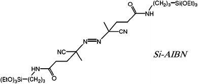
Here, drawing from our previous work on coating conformally three-dimensional assemblies of silica nanoparticles with polymers using surface initiated polymerization (SIP),20 we use R′ = 2,2′-azobisisobutyronitrile (AIBN) and introduce an alternative method for coating glass and oxidized metals with polymers. For this, a bidentate free radical initiator, Si-AIBNSi-AIBN, is attached covalently to a surface, and upon heating induces “grafting from” polymerization of monomers in contact with the surface.21 The method is predicated on the fact that polymers are end-capped with an initiator fragment. Experimental parameters are worked out with poly(methylmethacrylate) (PMMA) and poly(styrene) (PS). Subsequently, the findings are used to improve the adhesion of poly(3,4-ethylenedioxythiophene), PEDOT, arguably the most successful commercially conducting polymer manufactured and marketed by Bayer under the trade name Baytron® P. Baytron® P is an aqueous solution of the poly(styrenesulfonate), PSS, salt of the oxidized-conducting form of PEDOT and is used in antielectrostatic coatings.22
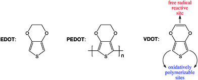
Since EDOT is not polymerizable by a free radical process, we have synthesized and used EDOT bifunctional analogues, 3,4-(vinylenedioxy)thiophene (VDOT), or 3,4-bis(vinyloxy)thiophene (BVOT), which have free radical reactive sites and a thiophene moiety that can be co-polymerized oxidatively with EDOT.23
Overall, the process of applying VDOT-EDOT films involves simple sol–gel chemistry and chemical oxidation, and can be integrated easily with conventional microfabication methods as demonstrated herewith with photolithographic patterning. Being covalently bonded to the substrate, the resulting VDOT-EDOT films are mechanically robust, hard, extremely adhering to the underlying surface, while they show similar electrical conductivity to PEDOT/PSS films obtained from Baytron® P.
2. Results and discussion
Covalent attachment of polymers to surfaces can be carried out either by “grafting to” or by “grafting from” methods. In both cases, prior to coating, the surface needs to be modified with appropriate functionality. In the “grafting to” approach bulk polymerization is carried out in the solution in contact with the surface; then, periodically, randomly growing polymeric chains engage the surface functionality and get attached to the substrate. The bulk of the polymer though is formed in the solution, hence the method is not appropriate for custom-synthesized, high value added monomers. Thus, here we have opted for a “grafting from” approach using a free radical polymerization method, whereas by employing a bidentate free radical initiator all polymer should be surface-confined, and precious unreacted monomer could be recovered. Clearly, this approach is based on the fact that in free radical polymerization polymeric chains are capped with an initiator fragment. As a suitable initiator for that purpose we use Si-AIBNSi-AIBN, which is synthesized in one step from 2,2′-azobiscyanovaleric acid and 3-aminopropyltriethoxysilane (APTES) as described before.20Si-AIBNSi-AIBN was stored as a THF stock solution, which was typically applied on glass slides by spin coating (see Experimental). Films were aged in the dark and their thickness was found at around 350 nm (by Dektak profilometry, see Figure S.1 in Electronic Supporting Information – ESI†). For its own merit, but also in order to work out experimental details, the method was first applied successfully on conventional polymers such as polystyrene (PS) and polymethylmethacrylate (PMMA), and only then onto high value added conducting PEDOT films. Glass slides 2′′ × 2′′ × 1/16′′ have been used as the typical substrate, even though films have been also grown with ease onto oxidized metal surfaces.2.1 Control case: PMMA and PS films on Si-AIBN modified glass
For this, two methods were followed. The first involves dipping and incubating initiator-coated glass slides in solutions of the monomer, while the second one involves spin-coating of a viscous prepolymer solution on top of the initiator layer followed by heating. For control, glass slides with no initiator were spin-coated with the prepolymer solution and heated. In all cases, at the end slides were cleaned by sonication in toluene to remove unbound polymer. No polymer layer was visible on the control slides. Initiator bearing slides appear macroscopically uniform, and profilometry shows that the prepolymer route yields thicker films (up to 4000 nm) than simple incubation in monomer solutions (150 nm, see Figure S.1 in ESI†). Since the prepolymer route is not a viable approach for the conducting polymer films described below, most further characterization, unless indicated otherwise, is based on films produced by dipping and incubating in monomer solutions.The chemical identify of the films was confirmed with IR spectroscopy (Fig. 1) by scraping material off glass slides. The IR spectra match those of commercial samples, although in the case of PS we see additional broad absorptions in the 3440 cm−1 and 1100 cm−1 range, probably owing to scraped off initiator layer that contains silica. The spatial arrangement of the polymer in the films (brushes versus globules) was investigated through molecular weight determinations and comparison of the film thickness with the polymer radius of gyration.24 Thus, washing PS films in boiling THF gives only small amounts of low molecular weight polymer (up to 1,000 - by Gel Permeation Chromatography). Treatment with aqueous HF etches the film off completely, but again consistently with similar previous attempts with PS-crosslinked silica aerogels made by the Si-AIBNSi-AIBN method,20 failed to give any higher molecular weight polymer. However, scraping the film off with a razor blade, and extracting with THF yielded almost monodispersed PS with Mn ∼ 110,000 and Mw ∼ 115,000 (see Figure S.2 and Table S.1 in ESI†). The radius of gyration, Rg, was calculated via the relationship given by Terao and Mays for PS in THF at 25 °C (Rg = 0.0118 × (Mw)0.6),24 and it was found equal to 12.8 nm, that is much smaller than the thickness of the films (∼150 nm) pointing to a brush-like structure. Conversely, a brush-like arrangement also implies high surface grafting density, σa, of the polymer chains. The latter is calculated via σa = 4/πs2, where s is the mean distance between the polymer chains on the surface; in turn, s is calculated from the layer (film) thickness, L (150 nm in our case), via Unsworth's relationship, s = [N3α5/L3]1/2,25 where α and N are the effective monomer length (0.26 nm, by molecular modeling using ChemDraw) and the degree of polymerization (1100), respectively. Thus, in our case s = 0.68 nm and σa = 2.75 chains/nm2, which, interestingly, is close to the –OH group surface density on amorphous sol–gel-derived silica (from tetramethylorthosilicate), whereas all Q3-silicon sites are terminated with hydroxyl groups (4.6 OH/nm2).26 (The difference is attributed to the length of the AIBN tether in Si-AIBNSi-AIBN.) When the mean distance between polymer chains, s, is much less than twice the Flory radius (RF = αN3/5), the grafted polymer is in brush form.27 Indeed, s/2RF = 0.020, that is ≪1, hence confirming again the same conclusion reached above via MW and Rg considerations about a brush-like structure.
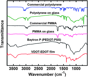 | ||
| Fig. 1 FTIR spectra of polystyerene (PS), PMMA and VDOT-EDOT scraped off films on glass slides, in comparison with commercial materials as indicated. | ||
As implied by the difficulty to remove films for the polymer characterization studies above, the adhesion of the polymer films on the glass slides is exceptional: a Tape Test (ASTM Designation: D 3359-97) that calls for drawing with a sharp object 100 squares (1 mm2 each) on the film and counting the number of squares surviving after the test, showed that all 100 squares remained intact, while no squares stayed on the surface from a control film made from a prepolymer solution on a clean, initiator-free slide. (For that control experiment, slides were not washed at the end – if washed the film is removed.) Clearly, the different adhesion characteristics have to be attributed to initiator (Si-AIBNSi-AIBN) mediated covalent bonding of the polymer films to the substrate.
A macroscopic visual confirmation of the adhesion of the polymer, with further implications in terms of integrating this process with classical microfabrication, was conducted as follows: a 2′′ × 2′′ glass slide was partially masked with a tape through its middle before spin-coating with the initiator solution. Subsequently, the tape was removed and the slide was processed with the viscous prepolymer as above. At the end, the slides were dried and sputter coated with Au. Ultrasonication in toluene dissolves the non-covalently bonded polymer film from the initiator-free zone and lifts off the Au layer above. Over the initiator bearing zones, the polymer together with its Au coating survived sonication completely. Fig. 2 shows the results and suggests that films derived by this method can withstand some of the most-harsh conditions used in microfabrication.
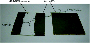 | ||
| Fig. 2 Au-sputtered, polystyrene-coated glass slides after lift-off by ultrasonication in toluene. Left: The clear zone was not derivatized with Si-AIBNSi-AIBN prior to polystyrene deposition from prepolymer (see Experimental); polystyrene and its Au-coating survive only over areas where polystyrene is covalently bonded to the substrate viaSi-AIBNSi-AIBN. Right: a similar slide, processed in parallel to the one at left, with uniform initiator coating. | ||
2.2 Electrically conducting polymer films on glass viaSIP
Among common conducting polymers, polyaniline is conducting in its two-electron oxidized, doubly protonated form (emeraldine salt) and is sensitive to acids and bases.28 On the other hand, polypyrroles have limited shelf-life,29 while polythiophenes appear the most versatile.23 Yet, the long-term stability of polythiophenes is compromised by the fact that the oxidized-conducting form is susceptible to nucleophilic attack in the 3- and 4- positions,30 as for example by water, leading to degradation and therefore to environmental instability. Preventing nucleophilic attack at those positions by substitution is a viable option, and thus poly(3-methylthiophene) is much more stable than polythiophene, and in fact is used in devices (e.g., transistors) submerged in water.31 The ultimate stability, of course, would result by blocking both the 3- and 4- positions, however, methyl hydrogens in poly(3,4-dimethylthiophene) get on the way of one another, forcing adjacent thiophenes out of the planarity required for extended conjugation and electrical conductivity. Thus, in the spirit used frequently in similar situations (e.g., aromatization of [10]annulene,32 or synthesis of dodecahydro-3α,9α-diazaperylene – the most easily oxidizable p-phenylenediamine,33) EDOT has been designed to eliminate such steric restrictions and PEDOT turns out the most successful commercially conducting polymer.Thus, although in analogy to styrene in Section 2.1, 3-vinylthiophene would probably be sufficient to demonstrate the properties of a conducting polythiophene film covalently attached to a substrate viaSIP, nevertheless the utility of such films would be limited, hence it was deemed appropriate to work with PEDOT for the reasons outlined above. As all thiophenes, EDOT is polymerizable through oxidative coupling in the 2- and 5- positions (not a free radical process). Typically, bulk oxidation of EDOT is carried out with FeCl3,34 since the polymer is formed in its oxidized state, the colorless-clear EDOT solution turns opaque-blue. Since EDOT cannot be attacked by radicals, we resorted to VDOT (although similar results have been also obtained with BVOT – see Scheme 1). Clearly, as far as the oxidizable (conducting) moiety (thiophene) and its substitution pattern are concerned, EDOT and VDOT (or BVOT) are equivalent. Indeed, electrochemically (Fig. 3) both EDOT and VDOT show an identical oxidation onset in acetonitrile at 1.2 V vs.Ag/AgCl (first potential sweep). Unlike EDOT, however, VDOT carries an isolated double bond prone to radical addition.
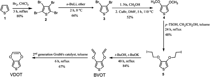 | ||
| Scheme 1 Synthesis of VDOT and BVOT. | ||
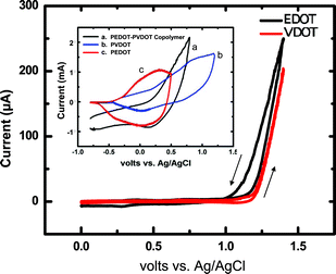 | ||
| Fig. 3 Magnified first-sweep cyclic voltammetry at the foot of the anodic waves (i.e., not the complete voltammograms) showing the common onset of oxidation of VDOT and EDOT in Ar-degassed acetonitrile containing 0.1 M TBAP as supporting electrolyte. Other parameters: sweep rate 0.1 V s−1; Pt electrode (0.0314 cm2); concentrations of VDOT and EDOT 0.1 M. The higher current in the return sweep (i.e., in the negative direction) is due to electrodeposited polymer. Inset: Cyclic voltammetry at 0.1 V s−1 of films as shown, grown on Pt disk electrodes from CH3CN/0.1 M TBAP solutions of EDOT (0.2 M), VDOT (0.2 M) and EDOT-VDOT (0.1 M in each) by repetitive sweeping of the potential from 0 V to 2.5 V vs. aq. Ag/AgCl at 0.1 V s−1. | ||
VDOT was synthesized from thiophene in satisfactory yields by modification of literature procedures according to Scheme 1.35–39 It is noted that traditional synthesis of EDOT is a five-step process,40 but more recently a convenient synthesis has been described through a common intermediate with the VDOT process, namely compound 4 (3,4-dimethoxythiophene, Scheme 1),41 so that the overall synthesis of VDOT is only two steps longer than the shortest route to EDOT.
Based on the findings with PS and PMMA, neat VDOT (or BVOT) was applied and spread evenly with a brush over glass slides, which had been spin-coated previously with the initiator (Si-AIBNSi-AIBN). However, after heating, aging and FeCl3 treatment, VDOT-modified glass slides failed to give the characteristic blue color expected from the oxidized-conducting form of the polymer, and indeed the substrate remained electrically insulating. At that point it was reasoned that the random and fairly rigid stereochemical arrangement of the thiophene moieties on the glass surface (refer to Scheme 2) was preventing them from reaching and coupling with one another via their 2- and 5- positions. Since VDOT and EDOT have the same onset for oxidation (Fig. 3), EDOT could be grafted to surface-confined VDOT (provided that the latter is indeed on the surface), by simultaneous FeCl3-oxidation of both moieties. The ability of EDOT and VDOT to co-polymerize was evaluated by electrochemical co-polymerization of a 1![[thin space (1/6-em)]](https://www.rsc.org/images/entities/char_2009.gif) :
:![[thin space (1/6-em)]](https://www.rsc.org/images/entities/char_2009.gif) 1 mol/mol solution of the monomers, and upon electrochemical characterization in fresh electrolyte (no monomers present) the resulting films show a redox wave between those of the two independent films (see Fig. 3, inset). As expected, of course, those films demonstrate poor adhesion to the electrode surface. On the other hand, films obtained by chemical polymerization of EDOT engaging surface bound VDOT would remain covalently bonded to the substrate and therefore should be extremely robust.
1 mol/mol solution of the monomers, and upon electrochemical characterization in fresh electrolyte (no monomers present) the resulting films show a redox wave between those of the two independent films (see Fig. 3, inset). As expected, of course, those films demonstrate poor adhesion to the electrode surface. On the other hand, films obtained by chemical polymerization of EDOT engaging surface bound VDOT would remain covalently bonded to the substrate and therefore should be extremely robust.
 | ||
| Scheme 2 Co-polymerization of VDOT and EDOT on a Si-AIBNSi-AIBN/VDOT-modified surface. The brush-like structure proposed is based on film-thickness considerations (see text). | ||
Scheme 3 summarizes the practical implementation of the process outlined above, and includes patterning of the resulting films by classical positive resist photolithography. Thus, dipping a colorless VDOT modified glass slide in a FeCl3 solution in acetonitrile, followed by addition of EDOT produced an opaque-blue solution that settles into a blue precipitate upon standing, and left a deep blue coating on the VDOT-modified glass slide. Brief ultrasonication in acetonitrile removed all loosely held polymer from the glass slide, leaving behind a transparent light-blue film that is not affected by further ultrasonication (even lasting for several hours). The films are macroscopically uniform (Fig. 4) and microscopically fairly smooth (inset in Fig. 4, and Fig. 5). By profilometry, the film thickness was similar to what was measured for PMMA and PS films obtained by incubation of Si-AIBNSi-AIBN modified glass slides in the monomer solutions (about 150 nm, compare inset in Fig. 4 with Figure S.1 in ESI†). Patterning is carried out by applying photoresist to protect the areas where the film is intended to survive, followed by etching off (with HF) the photoresist unprotected areas (Scheme 3). Remaining photoresist over the blue film was removed with acetone. A photograph of a typical patterned film, made using a photomask from previous studies,42 is included in Fig. 4.
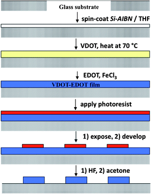 | ||
| Scheme 3 Process summary for applying covalently bonded, conducting VDOT-EDOT films on glass and photolithographic patterning. | ||
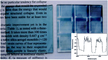 | ||
| Fig. 4 Optical photographs of BVOT-EDOT films on 2′′ × 2′′ glass slides obtained by the process outlined in Scheme 3. Left, before; Right, after photolithographic patterning. (Inset: Dektak profilometry on the patterned substrate). | ||
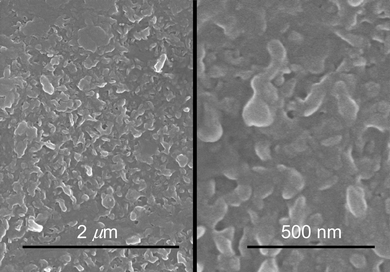 | ||
| Fig. 5 SEM at two different magnifications of a VDOT-EDOT film obtained by the process of Schemes 2 and 3. | ||
Control slides were prepared by replacing VDOT with EDOT in the process of Scheme 3. No blue deposit was visible on those surfaces, suggesting the absence of a thiophene film. Indeed, XPS analysis shows no sulfur (Fig. 6A), whereas sulfur is prominent in films obtained by the VDOT process (Fig. 6B). By IR (Fig. 2) material scraped off glass slides shows similar absorptions as commercial Baytron® P. (It is noted that the polystyrene sulfonate absorptions in the IR spectrum of Baytron® P are much weaker relative to those of the PEDOT moiety.) On the other hand, contrary to PS films, our attempts to extract the polymer from scraped off films were completely unsuccessful. Thus, molecular weight determinations have not been possible. On the other hand, however, considering the film thickness at L ∼ 150 nm, the grafting density should be similar to that calculated for PS films above, with also similar mean grafting distance between polymer chains. That again points to a dense brush-like structure for the polymer chains as shown in Scheme 2.
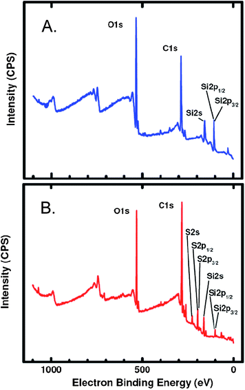 | ||
| Fig. 6 XPS analysis of Si-AIBNSi-AIBN modified glass slides processed according to Scheme 3. (A) Control slide whereas in the process of Scheme 3VDOT was replaced by EDOT (no blue color was seen on the final product); (B) a VDOT-EDOT film as described in Scheme 3. | ||
The quality of the VDOT-EDOT films in terms of pinholes was evaluated electrochemically. Fig. 7 compares the electrochemical response towards ferrocene oxidation of a Pt-coated glass slide, an initiator-modified Pt-coated glass slide, and a VDOT-EDOT film applied by the process of Scheme 3 on an initiator-modified, Pt-coated glass slide. The Pt-coated glass slide shows the expected diffusion-controlled redox wave of ferrocene (Fig. 7A). Pt can be surface-oxidized and the oxide film may be used for the covalent attachment of (RO)3Si-terminated moieties like Si-AIBNSi-AIBN.43 The ferrocene wave is still detectable on such initiator-modified Pt-coated glass slides, albeit greatly reduced (peak height ratio ∼80![[thin space (1/6-em)]](https://www.rsc.org/images/entities/char_2009.gif) :
:![[thin space (1/6-em)]](https://www.rsc.org/images/entities/char_2009.gif) 1), suggesting the presence of some pinholes (Fig. 7B). On the other hand, the ferrocene wave is completely absent from the VDOT-EDOT film-coated slide (Fig. 7C) suggesting that all pinholes in the sol–gel-derived initiator layer have been blocked. Interestingly, no redox wave associated with the VDOT-EDOT film is observed either, consistent with the slow electron transfer rate expected via the 150 nm thick sol–gel initiator layer (distance attenuation factor for long-range electron transfer ∼10 nm−1).44
1), suggesting the presence of some pinholes (Fig. 7B). On the other hand, the ferrocene wave is completely absent from the VDOT-EDOT film-coated slide (Fig. 7C) suggesting that all pinholes in the sol–gel-derived initiator layer have been blocked. Interestingly, no redox wave associated with the VDOT-EDOT film is observed either, consistent with the slow electron transfer rate expected via the 150 nm thick sol–gel initiator layer (distance attenuation factor for long-range electron transfer ∼10 nm−1).44
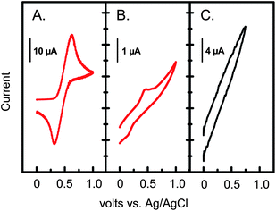 | ||
| Fig. 7 Electrochemistry at 0.1 V s−1 of ferrocene (3 mM) in an Ar-degassed CH3CN/0.1 M TBAP solution, using: (A) a Pt-coated glass slide (∼0.7 cm2). (B) Si-AIBNSi-AIBN modified, Pt-coated glass slide; (C) a VDOT-EDOT film on a Si-AIBNSi-AIBN modified, Pt-coated glass slide. | ||
Finally, VDOT-EDOT films were evaluated for their electrical conductivity, adhesion and hardness in comparison to PEDOT/PSS films obtained by spin-coating of commercial Baytron® P on similar 2′′ × 2′′ glass slides. Table 1 summarizes the results. The conductivity of typical VDOT-EDOT films was measured with a four-point probe and it was found to be 52 mho cm−1, comparable to that of PEDOT/PSS films of similar thickness (150 nm). Again, similarly to the results obtained with PMMA and polystyrene films, VDOT-EDOT films show excellent adhesion retaining all 100 squares of the grid after a tape adhesion test, while the entire PEDOT/PSS film was lifted completely. The film hardness, evaluated by a pencil test (ASTM D 3363-00), was found higher than 6H, while that of the PEDOT/PSS films was just at the HB level. For further comparison, the hardness of poly-3-methylthiophene films has been found <6B, while by introducing molecular crosslinking at the monomer level prior to electropolymerization via esterification of 3-(3-thienyl)ethanol and 3-thienylacetic acid the hardness had improved only up to the 3H level.45
| Property | VDOT-EDOT (this study) | PEDOT/PSS (Baytron® P) |
|---|---|---|
| a According to ASTM D 3359-97, 5B means that the edges of the cuts are completely smooth; none of the squares of the grid is detached. b According to the same standard, 0B means that the coating has flaked along the edges of cuts in large ribbons and whole squares have been detached. The area affected should be more than 35 to 65% of the grid. In this case, 100% of the grid was removed. | ||
| Thickness (nm) | 150 | 150 |
| Conductivity (mho cm−1) | 52 | 59 |
| Adhesion (ASTM D 3359-97) | 5Ba | 0Bb |
| Pencil hardness (ASTM D 3363-00) | >6H | HB |
3. Experimental
3.1 Materials
Thiophene, bromine, methylene chloride and t-butanol were purchased from Acros and were used as received unless noted otherwise. Chloroform, n-butyllithium (2 M solution in hexane), anhydrous DMF, anhydrous methanol, 2-iodoethanol and potassium t-butoxide, were used as received from Aldrich. Tetrahydrofuran (THF), diethyl ether, sodium hydroxide, cuprous bromide, p-toluenesulfonic acid, toluene, sodium sulfate, and sodium bisulfite were purchased from Fisher Scientific. t-Butanol and diethyl ether were dried by refluxing over sodium metal (from Fluka) for 3 h followed by distillation. THF was dried by refluxing over lithium aluminum hydride for 3 h followed by ditrillation. Cuprous bromide was dried in an oven at 200 °C for 12 h before use. Toluene was dried by refluxing over phosphorous pentoxide for 3 h followed by distillation. Styrene and methyl methacrylate (MMA) were purchased from Aldrich Chemical Co., washed with 5% sodium hydroxide solution to remove the inhibitor, and purified by distillation under reduced pressure. N2 was obtained from BOC Gases, Murray Hill, N.J. supplied locally by Ozarc Gas. Si-AIBNSi-AIBN was prepared as reported before, and was stored as a 0.112 M solution in THF.20Tetrabutylammonium perchlorate (TBAP) was also prepared as described before.463.2 Synthesis of 3,4-(vinylenedioxy)thiophene (VDOT)
VDOT was synthesized by modification of literature procedures as follows (Scheme 1).35–39![[thin space (1/6-em)]](https://www.rsc.org/images/entities/char_2009.gif) :
:![[thin space (1/6-em)]](https://www.rsc.org/images/entities/char_2009.gif) 3 v/v). All solvents were removed with a rotary evaporator and the product was collected as a yellow solid. Yield: 0.70 g (48%); mp 85–88 °C (lit.37 86 °C); 1H NMR: δ (ppm) 3.42 (t, J = 7.4 Hz, 4H), 4.25 (t, J = 7.4 Hz, 4H), 6.26 (s, 2H); 13C NMR: δ (ppm) 0.5 (-CH2I), 71.0 (-OCH2-), 99.4, 145.9.
3 v/v). All solvents were removed with a rotary evaporator and the product was collected as a yellow solid. Yield: 0.70 g (48%); mp 85–88 °C (lit.37 86 °C); 1H NMR: δ (ppm) 3.42 (t, J = 7.4 Hz, 4H), 4.25 (t, J = 7.4 Hz, 4H), 6.26 (s, 2H); 13C NMR: δ (ppm) 0.5 (-CH2I), 71.0 (-OCH2-), 99.4, 145.9.
![[thin space (1/6-em)]](https://www.rsc.org/images/entities/char_2009.gif) :
:![[thin space (1/6-em)]](https://www.rsc.org/images/entities/char_2009.gif) 1, v/v). All solvents were removed with a rotary evaporator and the product was obtained as a pale yellow liquid. Yield: 0.33 g (84%); bp 181–190 °C (in a sealed capillary tube; polymerized); 1H NMR: δ (ppm) 4.45(dd, J = 6.0 Hz, 2.0 Hz, 2H), 4.81(dd, J = 11.8 Hz, 2.0 Hz, 2H),6.54 (s, 2H), 6.60 (dd, J = 11.8 Hz, 6.0 Hz, 2H); 13C NMR: δ (ppm) 95.3 (
1, v/v). All solvents were removed with a rotary evaporator and the product was obtained as a pale yellow liquid. Yield: 0.33 g (84%); bp 181–190 °C (in a sealed capillary tube; polymerized); 1H NMR: δ (ppm) 4.45(dd, J = 6.0 Hz, 2.0 Hz, 2H), 4.81(dd, J = 11.8 Hz, 2.0 Hz, 2H),6.54 (s, 2H), 6.60 (dd, J = 11.8 Hz, 6.0 Hz, 2H); 13C NMR: δ (ppm) 95.3 (![[double bond, length as m-dash]](https://www.rsc.org/images/entities/char_e001.gif) CH2), 103.8, 144.3 (-OCH
CH2), 103.8, 144.3 (-OCH![[double bond, length as m-dash]](https://www.rsc.org/images/entities/char_e001.gif) ), 148.5.
), 148.5.
![[thin space (1/6-em)]](https://www.rsc.org/images/entities/char_2009.gif) :
:![[thin space (1/6-em)]](https://www.rsc.org/images/entities/char_2009.gif) 40 v/v). The pure product was isolated as a yellow viscous oil. Yield: 0.330 g (67%); bp 130–140 °C (polymerized); 1H NMR: δ (ppm) 5.91 (s, 2H), 6.26 (s, 2H); 13C NMR: δ (ppm) 101.2, 125.2 (-OCH
40 v/v). The pure product was isolated as a yellow viscous oil. Yield: 0.330 g (67%); bp 130–140 °C (polymerized); 1H NMR: δ (ppm) 5.91 (s, 2H), 6.26 (s, 2H); 13C NMR: δ (ppm) 101.2, 125.2 (-OCH![[double bond, length as m-dash]](https://www.rsc.org/images/entities/char_e001.gif) ), 176.3.
), 176.3.
3.3 Preparation of polystyrene (PS) and polymethylmethacrylate (PMMA) films on glass surfaces
Glass slides (2′′ × 2′′ × 1/16′′) were cleaned by boiling for 2 min in Micro™ solution, followed by washing with copious amounts of deionized water and then boiling again in water for 2 min. Slides were bench-dried in vertical position for 24 h. The THF stock solution of Si-AIBNSi-AIBN was applied two times on those glass slides by spin coating (30 s at 1500 rpm). Such Si-AIBNSi-AIBN modified glass slides were aged in the dark for 24 h before further processing. PS and PMMA films were grown in two ways: from monomer solutions or from prepolymers.![[thin space (1/6-em)]](https://www.rsc.org/images/entities/char_2009.gif) :
:![[thin space (1/6-em)]](https://www.rsc.org/images/entities/char_2009.gif) 50 v/v solution of inhibitor-free MMA in toluene, or inhibitor-free styrene were heated separately at 130 °C in closed containers for 6 h with no initiator. At the end of this period, those freshly prepared viscous polymers were applied on Si-AIBNSi-AIBN modified glass slides by spin-coating for 30 s at 1500 rpm. The films prepared by this method were cured for 6 h at 70 °C, followed by ultrasonication and bench-drying. Again as a control, glass plates without Si-AIBNSi-AIBN modification were processed in the same manner.
50 v/v solution of inhibitor-free MMA in toluene, or inhibitor-free styrene were heated separately at 130 °C in closed containers for 6 h with no initiator. At the end of this period, those freshly prepared viscous polymers were applied on Si-AIBNSi-AIBN modified glass slides by spin-coating for 30 s at 1500 rpm. The films prepared by this method were cured for 6 h at 70 °C, followed by ultrasonication and bench-drying. Again as a control, glass plates without Si-AIBNSi-AIBN modification were processed in the same manner.
3.4 Preparation of VDOT-EDOT films on glass surfaces and photolithographic patterning
VDOT (or BVOT) was applied by brush over Si-AIBNSi-AIBN modified glass slides, which were kept in an airtight glass container at 70 °C for 12 h. Unreacted VDOT (or BVOT) was removed by dipping the film in CH3CN. Subsequently, dry films were dipped in a 1 M FeCl3 solution in CH3CN. EDOT was added to that solution to a final concentration 50 mM. The container was manually agitated and after 10 min, the glass slides were removed, washed with CH3CN and ultrasonicated in fresh CH3CN for 1 min. To the above prepared blue VDOT-EDOT films, positive photoresist (Shipley Megaposit SPR 510-A) was applied by spin coating (1500 rpm, 45 s, acceleration rate of 200 rps) followed by soft-baking at 100 °C for 2 min in a convection oven. The photoresist was contact-exposed through a mask available from previous work42 to the long wavelength (365 nm) of a hand-held UV source for 20 min. The exposed resist was developed with a photoresist developer (Shipley Microposit MF-312) leaving behind the desirable pattern over the VDOT-EDOT polymer film. Other details related to the photolithographic process can be found in ref. 38. Finally, VDOT-EDOT films coated with patterned photoresist were dipped in a 10% w/w HF solution for 8–10 s removing the photoresist-unprotected blue film. The remaining photoresist was removed with acetone, leaving behind a patterned covalently bonded conducting polymer film of VDOT-EDOT on the glass slide. Photolithography conducted in a similar manner on plain glass does not form any pattern, confirming that HF treatment under our conditions etches only the sol–gel film.3.5 Methods
Intermediates along the VDOT synthesis and also Si-AIBNSi-AIBN were characterized by 1H and 13C NMR in CDCl3 using a 400 MHz Varian Unity Inova NMR instrument. Film thicknesses were measured with a Dektak II profilometer by scratching notches on their surfaces with a razor blade. Infrared spectra were obtained with a Nicolet-FTIR Model 750 Spectrometer in KBr pellets with samples collected by scraping off films from their substrates. Number- and weight-average molecular weights (Mn and Mw, respectively) and polydispersity indexes (Mw/Mn) were determined by gel permeation chromatography (GPC).47GPC was conducted using a Shodex GPC KH-803L column connected to a Schimadzu liquid chromatograph (LC-10AD) equipped with a UV-Vis detector (SPD-10AV). Tetrahydrofuran (THF) was used as eluent at 1 mL min−1. Linear polystyrene standards from Varian (Polystyrene Low EasiVials; Part No. PL2010-0400 and PL2010-0403) were used for calibration. Polystyrene coated on glass was scraped off using a knife and extracted with THF (2 mL). The injection volume for GPC was 10 μL. Four-point-probe conductivity measurements were conducted using an Alesis contact probe station Model CPS-06 with a Cascade Microtech electrode Model C4S-44/5S. The reliability of the probe was confirmed with commercially available silicon wafers and indium-tin-oxide films of known sheet resistance. XPS spectra were obtained using a Physical Electronics Model 548 ESCA/Auger spectrometer. Scanning electron microscopy was conducted with films coated with Au using a Hitachi S-4700 field emission microscope. The redox characteristics of the monomers (VDOT and EDOT) were evaluated with standard millielectrode cyclic voltammetry with a Pt disk electrode (2 mm diameter) in CH3CN/0.1 M TBAP and an EG&G 263A potentiostat controlled by the EG&G model 270/250 software. The quality of VDOT-EDOT films (in terms of pinholes) was also evaluated electrochemically, using Cr/Pt sputter coated glass slides and ferrocene (3 mM)/CH3CN/0.1 M TBAP as a reference redox system. The films were also characterized for adhesion according to ASTM D3359-97 using a Scotch Tape from 3M as specified by the standard. For this purpose, a 10 × 10 grid of cuts was made on the surface of the film using a blade and then scotch tape was applied on the grid making sure that there are no air bubbles between the tape and the grid. The tape was pulled off rapidly and the number of squares that came off determined the adhesion of the film. Film hardness was determined according to ASTM D 3363-00 standard test method for film hardness by pencil test.4. Conclusion
Polymer films need to be applied on surfaces for a variety of applications. Improving their adhesion is of technological significance in terms of increasing their useful lifetime or their survivability in adverse environments. Physically adsorbed films are the most delicate, and they may become more robust by molecular crosslinking of the polymeric chains;45 but ultimately, however, the best approach is to introduce covalent bonding between the film and the substrate. Here, reasoning that all polymer chains are capped with initiator fragments, the advantages of covalent bonding with the substrate were demonstrated by attaching covalently a free radical initiator on the surface to be polymer-coated. At that point, coating glass with polystyrene or PMMA was rather straightforward. In addition to glass, similar films have been applied to metals (e.g., aluminum, steel) and may serve as protection against corrosion. However, the power of this approach is that by judicious choice of the monomer, in combination with follow-up chemistry, the method can be extended to polymeric systems that typically elude covalent attachment to surfaces such as thiophenes and most notably EDOT. The resulting films show superior adhesion, solvent resistance and hardness. Consequently, it was also demonstrated that their processing can be integrated with conventional photolithography without compromising their electrical conductivity relative to physically attached commercial products.Acknowledgements
This project was supported by the National Science Foundation under Agreement No. CHE-0809562 and CMMI-0653970, and the Army Research Office under Award No. W911NF-10-1-0476. We also acknowledge the Materials Research Center of Missouri S&T for support in sample characterization (SEM, XPS). We also thank Bayer Corporation USA for the generous supply of a Baytron® P sample.References
- S. Moulay, C. R. Chim., 2009, 12, 577–601 CrossRef CAS; G. Zotti and B. Vercelli, Acc. Chem. Res., 2008, 41, 1098–1109 CrossRef; S. Gabriel, R. Jérôme and C. Jérôme, Prog. Polym. Sci., 2010, 35, 113–140 CrossRef.
- H. Shirakawa, Angew. Chem., Int. Ed., 2001, 40, 2574–2580 CrossRef CAS; A. G. MacDiarmid, Angew. Chem., Int. Ed., 2001, 40, 2581–2590 CrossRef; A. J. Heeger, Angew. Chem., Int. Ed., 2001, 40, 2591–2611 CrossRef.
- J. H. Burroughes, D. D. C. Bradley, A. R. Brown, R. N. Marks, K. Mackay, R. H. Friend, P. L. Burn and A. B. Holmes, Nature, 1990, 347, 539–541 CrossRef CAS; E. W. H. Jager, E. Smela and O. Inganäs, Science, 2000, 290, 1540–1546 CrossRef.
- F. Faverolle, A. J. Attias, B. Bloch, P. Audebert and C. P. Andrieux, Chem. Mater., 1998, 10, 740–752 CrossRef CAS.
- S. Oberoi, E. Jaehne and H. P. Adler, Macromol. Symp., 2007, 254, 284–291 CAS.
- S. Oberoi, E. Jaehne and H. P. Adler, Macromol. Symp., 2004, 217, 147–159 CrossRef CAS.
- D. E. Labaye, C. Jérôme, V. M. Geskin, P. Louette, R. Lazzaroni, L. Martinot and R. Jérôme, Langmuir, 2002, 18, 5222–5230 CrossRef CAS.
- B. Fabre and D. D. M. Wayner, Langmuir, 2003, 19, 7145–7146 CrossRef CAS.
- B. Fabre and D. D. M. Wayner, C. R. Chim., 2005, 8, 1249–1255 CrossRef CAS.
- B. Fabre, G. P. Lopinski and D. D. M. Wayner, Chem. Commun., 2002, 2904–2905 RSC.
- N. Y. Kim and P. E. Laibinis, J. Am. Chem. Soc., 1999, 121, 7162–7163 CrossRef CAS.
- W. D. Bascom, Macromolecules, 1972, 5, 792–798 CrossRef CAS.
- P. H. Harding and J. C. Berg, J. Adhes. Sci. Technol., 1997, 11, 471–493 CrossRef CAS.
- G. L. Witucki, J. Coat. Technol., 1993, 65, 57–60 Search PubMed; S. P. Kotha, M. Lieberman, A. Vickers, S. R. Schmid and J. Mason, J. Biomed. Mater. Res., Part A, 2006, 76, 111–119 CrossRef CAS.
- R. A. Simon, A. J. Ricco and M. S. Wrighton, J. Am. Chem. Soc., 1982, 104, 2031–2034 CrossRef CAS.
- I. Imae, S. Takayama, D. Tokita, Y. Ooyama, K. Komaguchi, J. Ohshita, T. Sugioka, K. Kanehira and Y. Harima, Polymer, 2009, 50, 6198–6201 CrossRef CAS.
- B. Dong, D. Zhong, L. Chi and H. Fuchs, Adv. Mater., 2005, 17, 2736–2741 CrossRef CAS.
- Y. Zhang, C. Wang, L. Rothberg and M. Ng, J. Mater. Chem., 2006, 16, 3721–3725 RSC.
- D. Appelhans, D. Ferse, H. J. P. Adler, W. Plieth, A. Fikus, K. Grundke, F. J. Schmitt, T. Bayer and B. Adolphi, Colloids Surf., A, 2000, 161, 203–212 CrossRef CAS.
- S. Mulik, C. Sotiriou-Leventis, G. Churu, H. Lu and N. Leventis, Chem. Mater., 2008, 20, 5035–5046 CrossRef CAS; N. Leventis, S. Mulik and C. Sotiriou-Leventis, Polym. Prepr., 2007, 48, 950–951 Search PubMed.
- X. Huang and W. J. Brittain, Macromolecules, 2001, 34, 3255–3260 CrossRef CAS.
- L. B. Groenendaal, F. Jonas, D. Freitag, H. Pielartzik and J. R. Reynolds, Adv. Mater., 2000, 12, 481–494 CrossRef CAS.
- J. Roncali, Chem. Rev., 1992, 92, 711–738 CrossRef CAS.
- K. Terao and J. W. Mays, Eur. Polym. J., 2004, 40, 1623–1627 CrossRef CAS.
- L. D. Unsworth, Z. Tum, H. Sheardown and J. L. Brash, J. Colloid Interface Sci., 2006, 296, 520–526 CrossRef CAS; Z. Tun, L. D. Unsworth, J. L. Brash and H. Sheardown, Phys. B, 2006, 385–386, 697–699 CrossRef.
- C. J. Brinker and G. W. Scherer, Sol–Gel Science: The Physics and Chemistry of Sol–Gel Processing, Academic Press, Inc., San Diego, CA, 1990, p 626 Search PubMed.
- K. N. Plunkett, X. Zhu, J. S. Moore and D. E. Leckband, Langmuir, 2006, 22, 4259–4266 CrossRef CAS.
- A. J. Epstein, J. M. Ginder, F. Zuo, H.-S. Woo, D. B. Tanner, A. F. Richter, M. Angelopoulos, W.-S. Huang and A. G. MacDiarmid, Synth. Met., 1987, 21, 63–70 CrossRef CAS; R. S. Kohlman and A. J. Epstein, in: T. A. Skotheim, R. L. Elsenbaumer, J. R. Reynolds (ed.), Handbook of Conducting Polymers Revised and Expanded, 2nd ed., Marcel Dekker, Inc., New York, NY, 1998, pp. 85–121 (Chapter 3) Search PubMed.
- A. Kros, N. A. J. M. Sommerdijk and R. J. M. Nolte, Sens. Actuators, B, 2005, 106, 289–295 CrossRef.
- Z. Qi, N. G. Rees and P. G. Pickup, Chem. Mater., 1996, 8, 701–707 CrossRef CAS.
- J. W. Thackeray, H. S. White and M. S. Wrighton, J. Phys. Chem., 1985, 89, 5133–5140 CrossRef CAS; T. M. Swager, Acc. Chem. Res., 1998, 31, 201–207 CrossRef.
- M. B. Smith and J. March, March's Advanced Organic Chemistry Reactions Mechanisms and Structure Fifth Edition, John Wiley & Sons, Inc., New York, N.Y, 2001, p 63 Search PubMed.
- A.-M. M. Rawashdeh, C. Sotiriou-Leventis, X. Gao and N. Leventis, Chem. Commun., 2001, 1742–1743 RSC.
- A. O. Sarhan and C. Bolm, Chem. Soc. Rev., 2009, 38, 2730–2744 RSC.
- F. Goldoni, B. M. W. Langeveld-Voss and E. W. Meijer, Synth. Commun., 1998, 28, 2237–2244 CrossRef CAS.
- M. A. Keegstra, T. H. A. Peters and L. Brandsma, Synth. Commun., 1990, 20, 213–216 CrossRef CAS.
- P. Leriche, P. Blanchard, P. Frere, E. Levillain, G. Mabon and J. Roncali, Chem. Commun., 2006, 275–277 RSC.
- B. H. Kim, M. S. Kim, K. T. Park, J. K. Lee, D. H. Park, J. Joo, S. G. Yu and S. H. Lee, Appl. Phys. Lett., 2003, 83, 539–541 CrossRef CAS.
- B. M. W. Langeveld-Voss, R. A. J. Janssen and E. W. Meijer, J. Mol. Struct., 2000, 521, 285–301 CrossRef CAS.
- E. W. Fager, J. Am. Chem. Soc., 1945, 67, 2217–2218 CrossRef CAS; J. Z. Mortensen, B. Hedegaard and S.-O. Lawesson, Tetrahedron, 1971, 27, 3839–3951 CrossRef; D. Caras-Quintero and P. Bauerle, Chem. Commun., 2002, 2690–2691 RSC.
- F. von Kieseritzky, F. Allared, E. Dahlstedt and J. Hellberg, Tetrahedron Lett., 2004, 45, 6049–6050 CrossRef CAS.
- E. W. Bohannan, X. Gao, K. R. Gaston, C. D. Doss, C. Sotiriou-Leventis and N. Leventis, J. Sol-Gel Sci. Technol., 2002, 23, 235–245 CrossRef CAS.
- H. Luo, S. Park, H. Y. H. Chan and M. J. Weaver, J. Phys. Chem. B, 2000, 104, 8250–8258 CrossRef CAS.
- C. Amatore, Y. Bouret, E. Maisinhaute, H. D. Abruña and J. I. C. R. Goldsmith, C. R. Chim., 2003, 6, 99–115 CrossRef CAS.
- A. Dass, S. Mulik, C. Sotiriou-Leventis and N. Leventis, Synth. Met., 2006, 156, 966–972 CrossRef CAS.
- N. Leventis, M. Chen, X. Gao, M. Canalas and P. Zhang, J. Phys. Chem. B, 1998, 102, 3512–3522 CrossRef CAS; N. Leventis and X. Gao, J. Phys. Chem. B, 1999, 103, 5832–5840 CrossRef.
- D. J. Harmon, J. Polym. Sci., 1965, C8, 243–251 Search PubMed; J. A. May, Jr. and W. B. Smith, J. Phys. Chem., 1968, 72, 216–221 CrossRef.
Footnote |
| † Electronic supplementary information (ESI) available: Profilometry of a typical Si-AIBNSi-AIBN film spin-coated on a glass slide and of various PMMA films grown by various methods. GPC of PS extracted by scraping material off glass slides. See DOI: 10.1039/c1jm12563j |
| This journal is © The Royal Society of Chemistry 2012 |

