In situ characterization of infrared femtosecond laser ablation in geological samples. Part A: the laser induced damage
François-Xavier
D'Abzac
*a,
Anne-Magali
Seydoux-Guillaume
a,
Jérôme
Chmeleff
a,
Lucien
Datas
b and
Franck
Poitrasson
a
aGET, UMR 5563 CNRS—Université de Toulouse—IRD—OMP, 14 avenue Edouard Belin, 31400, Toulouse, France. E-mail: dabzac@lmtg.obs-mip.fr
bTEMSCAN—CIRIMAT—Université de Toulouse, 118 route de Narbonne, 31400, Toulouse, France
First published on 26th October 2011
Abstract
Infrared femtosecond laser induced damage has been studied in order to determine, with analytical protocols, the processes involved in laser ablation in this regime. Transmission Electron Microscopy (TEM) coupled with Focused Ion Beam (FIB) milled cross-sections of natural ablated monazite were used. Craters were formed using N = 1 and 3 shots, E0 = 0.1 and 0.8 mJ per pulse and τ = 60 fs. Observations revealed that laser settings induce little changes in the nature and size of damaged structures. The crater bottom forms a ∼0.5 μm layer composed of melted and recrystallized monazite grains, and spherical ∼10 nm voids. The underlying sample shows lattice distortions, progressively attenuated with depth, typical of mechanical shocks (thermoelastic relaxation and plasma recoil pressure). No chemical difference appears between these two domains, excluding preferential vaporization and thus laser induced chemical fractionation. Correlations with existing molecular dynamics (MD) simulations indicate that the deep distorted lattice probably undergoes spallation whereas the upper layer rather goes through homogeneous nucleation. Nevertheless, these processes are not pushed forward enough to induce matter removal in the present conditions. In consequence, photomechanical fragmentation and vaporization, requiring higher energy density states, would rather be the main ablation mechanisms. This hypothesis was supported by an additional study focused on the laser produced aerosols. Further links to LA-ICP-MS measurements can then be developed.
Introduction
Laser ablation is a powerful sampling technique, especially when coupled with Inductively Coupled Plasma Mass Spectrometry (LA-ICP-MS).1–3 Improvement of such a technique is linked to a full understanding and control of ablation mechanisms because of the need for stoichiometric sampling for accurate analyses. To do so it is important to constrain both the laser–matter interaction via the study of laser induced damages, and the aerosols produced by laser ablation and subsequently analyzed by ICP-MS.Nowadays laser ablation systems producing nanosecond time scale pulses are extensively used and have reached the limits of technical improvement for that purpose, principally with the use of better absorbed ultraviolet wavelengths.4 Nevertheless, in the nanosecond regime, ablation mainly occurs by sample fusion and melt ejection, because of considerable loss of pulse energy via thermal diffusion into the sample.5 The resulting ablation induces non-stoichiometric sampling, further causing chemical fractionation detectable in LA-ICP-MS measurements.6–8 The use of femtosecond pulses, with a duration below characteristic times for conduction or thermal diffusion, eliminates those issues and allows chemical fractionation free LA-ICP-MS measurements (within analytical precision).8,9 In this regime, pulse energy delivery is fast enough to favour multiphoton absorption and greatly increases the probability of triggering ablation,10 in contrast to nanosecond pulses for which this phenomenon is rather probabilistic.
In order to characterize laser ablation induced damages different analytical techniques can be useful. For instance Scanning Electron Microscopy (SEM) has been of great help in characterizing ablated structures11,12 and qualifying thermal and mechanical effects.13 Later on, Transmission Electron Microscopy (TEM) has given new insights into the field of study because of the possibility to perform, at much higher resolution, chemical analysis (Energy Dispersive X-Ray (EDX) spectroscopy) coupled to structural characterizations (selected area electron diffraction (SAED), bright field (BF), dark field (DF) images).14 Kosler et al.15 have used these complementary techniques in the study of zircon and synthetic glass ablation and reported the transformation of the initial mineral phase in UV nanosecond laser ablation. Other authors have demonstrated the efficiency of such a technique when combined with Focused Ion Beam (FIB) milling sampling, in order to perform an in-depth study of ablated structures of industrial alloys.16–18 Finally, some studies revealed the reduced thermal effects of femtosecond laser ablation in comparison with nanosecond damages, as well as a high density of defects due to the combined effects of shock wave propagation, thermal shock and quenching.14,19 On the other hand, theoretical works meticulously described the phase transitions undergone by matter irradiated by femtosecond pulses, through molecular dynamics (MD) simulations of simplified systems.20–24
The aim of the present work is the complete characterization of the mechanisms involved in near-infrared femtosecond laser ablation by in situ observations. Both the laser induced damages and the aerosols produced have been studied and results of observations are compared and correlated with existing theoretical models. Here craters formed under different laser ablation conditions were sampled using the FIB milling process, and carefully studied with TEM in order to constrain the laser–matter interactions within the IR femtosecond regime and model the ablation mechanisms. The direct link with LA-ICP-MS analyses, especially when dealing with the remaining limitations of this technique,25,26 is discussed and a continuation study dedicated to the laser produced aerosol is discussed in part B.
Experimental
Laser ablation
A commercial Ti:sapphire femtosecond system (Pulsar 10, Amplitude Technologies, Evry/Seine, France) was used. Specifications can be found in Freydier et al. (2008). The laser was operated at the fundamental wavelength (λ = 800 nm), using a Chirped Pulse Amplification system,27 with an output pulse duration and a maximum pulse energy of τ = 60 fs and E0 = 12 mJ per pulse respectively. Repetition rate, up to 10 Hz, was controlled by a mechanic shutter placed between the regenerative amplifier and the multi passage amplifier. Energy is controlled by a combination of a rotative half wave plate and twin polarisers. Pulse duration can be optimized by moving the second grating of the compressor stage, via a micrometric screw. Laser specifications and operating conditions are described in Table 1. The beam is focused through a modified optical microscope (BX51, Olympus, Hamburg, Germany), equipped with a XYZ motorized sample stage. The beam is focused on the target by a 50 mm focusing coated lens. Craters reach a diameter of about 80 μm. A cylindrical 25 cm3 ablation cell, mounted with a quartz window, was used. The sample is enclosed in a compound which can hold two polished sections, accustomed to fill empty volumes so as to stabilize the gas flow inside the cell. Viewing can be operated through the microscope binoculars or via a CCD camera placed at the top of the microscope. Aerosols are flushed off the cell by a 0.5 L min−1helium flow. The laser was set at τ = 60 fs and E0 = 0.1 and 0.8 mJ per pulse. Fluence on sample reaches 1.5 and 12.5 J cm−2 respectively.| Laser system | Amplitude technologies “Pulsar 10” |
|---|---|
| Wavelength | 800 nm (fundamental) |
| Repetition rate | 5 Hz |
| Pre-ablation laser warm up | 45 min |
| Pulse duration | 60 fs |
| Beam diameter | 10 mm |
| Focusing objective | 50 mm coated lens |
| Spot diameter | 90 μm |
| Maximum pulse energy | 12 mJ per pulse |
| Ablation cell | Cylindrical, 25 cm−3 |
| Carrier gas | Helium, 0.5 L min−1 |
Focused Ion Beam and Transmission Electron Microscopy
The “site specific” Focused Ion Beam (FIB) sampling has been described by Wirth.28 The technique is based on the milling of a thin foil (∼100 nm) in depth of a solid sample (∼10 μm). The process is achieved by a gallium ion beam after coating the sample surface with a protective platinum layer. After extraction, cut foils are placed on TEM sample grids. The choice of the sampling site has been made in order to observe the in-depth laser induced damage directly under the crater surface. The same protocol was applied by Seydoux-Guillaume et al.14 As the crater diameter (∼80 μm) is much larger than the maximum achievable foil length (∼15 μm), the sampling has been performed, as shown in Fig. 1, on a radial path inside the crater, at an equal distance between the centre and the outer border. Craters were formed using the laser settings reported in Table 1, with 1 and 3 consecutive shots at different pulse energies (0.1 and 0.8 mJ per pulse). Observations are conducted at the TEMSCAN service of the University of Toulouse. We used a JEOL 2100F Transmission Electron Microscope operated at 200 keV. The microscope is equipped with a field emission gun (FEG) as electron source, a high annular dark field (HAADF) detector, a STEM (Scanning Transmission Electron Microscope) mode, an Energy Dispersive X-Ray (EDX) analyzer system from Princeton Gamma Tech (Princeton, NJ, USA), and a CCD camera Gatan (Pleasanton, CA, USA) (1k × 1k).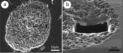 | ||
| Fig. 1 (A) Ablation crater in monazite (E0 = 0.8 mJ per pulse, τ = 60 fs and N = 5 shots) and the location of the corresponding FIB foil sampled within (black dashed line). (B) 45° tilt of the view, highlighting the foil. The size is 15 μm wide and 8 μm deep. Thickness is ∼100 nm in the centre area and enlarges to borders (darker contrast). | ||
Sample
The Moacyr monazite (LREE(PO4)) from Itambe pegmatite (Brazil) has been used for particle collection, counting and crater study. This monoclinic orthophosphate29 is of great interest in geology because of its high concentration of U–Th–Pb, making it a reliable geochronometer.30,31Monazite has been previously studied for its defect healing properties and its particular response to auto-irradiation,32 which make it a potential efficient phase for nuclear waste storage.33 Hence, its crystalline structure has been precisely characterized, and its chemical homogeneity has been demonstrated. Previous work even used Moacyr monazite as an analytical reference for developing LA-ICP-MS dating of various monazites.34 Its composition is reported in Table 2. Concentrations under 0.1 wt% are not given because they are undetectable by Energy Dispersive X-Ray analyses (see below).| Moacyr wt% | |
|---|---|
| P | 27.81 |
| Ca | 0.44 |
| Si | 1.42 |
| La | 14.51 |
| Ce | 30.59 |
| Pr | 3.14 |
| Nd | 10.2 |
| Sm | 2.05 |
| Gd | 0.94 |
| Dy | 0.11 |
| Er | 0.05 |
| Y | 0.71 |
| Pb | 0.16 |
| Th | 6.92 |
| U | 0.13 |
| Total | 99.18 |
Results
1 Surface structure
Fig. 1 is a SEM image that shows the crater surface structure for E0 = 0.8 mJ per pulse and N = 3. The outer borders show small cracks and thin material ejection traces. The pit has an irregular porous surface and shows traces of periodic structures.11 This morphology is similar to the observation of Seydoux-Guillaume et al.14 using similar laser settings, but a twice shorter focal length.2 In depth structures
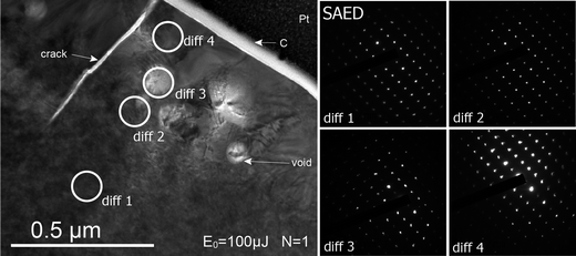 | ||
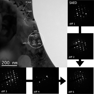
| Fig. 2 Bright Field Transmission Electron Microscopy pictures of the FIB foil cut into the monazite laser pit (E0 = 0.1 mJ per pulse, τ = 60 fs, N = 1 shot) with associated selected area electron diffraction (SAED) patterns “diff 1” to “diff 4” in which measurement areas are indicated as white circles. Note the natural mottled diffraction texture of the bulk crystal, disappearing in the superficial layer composed of healed monazite and spherical voids. Note the vertical crack affecting this layer. | ||
(i) The bulk sample, deeper than ∼500 nm, shows mottled diffraction contrasts resulting from irradiation damages due to thorium and uranium decays. This particular texture has been described in previous studies33,35–37 and is typical for monazite crystals. The first diffraction analysis (“diff 1”) shows a regular pattern with round diffraction spots of a well oriented monocrystal, corresponding to the undisturbed monazite lattice.
(ii) Shallower under the surface, a second zone is underlined by the absence of the above described mottled diffraction contrasts. Voids appear characterized by round clear features of ∼100 nm diameter. These are not perfectly round and defined, probably because the focused electron beam field depth is too short to resolve objects located under the observed surface. The structure of this shallow part (diff 3 and 4) slightly differs from the deep unaffected crystal. It is crystalline, yet diffraction spots (diff 4) are not as well defined and rounded as those for deep undamaged sample analysis (diff 1).
Finally, the crater bottom shows a regular plane surface. Rare cracks occur perpendicularly to the ablation pit with a maximum 0.5 μm depth.
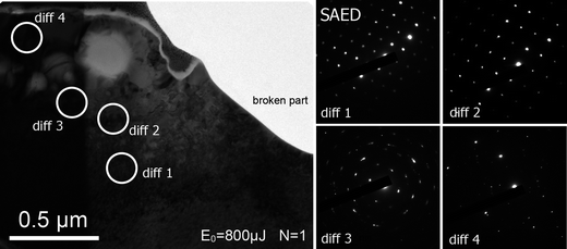 | ||
| Fig. 3 Bright Field Transmission Electron Microscopy pictures of the FIB foil cut into the monazite laser pit (E0 = 0.8 mJ per pulse, τ = 60 fs, N = 1 shot) with associated selected area electron diffraction (SAED) patterns “diff 1” to “diff 4” in which measurement areas are indicated as white circles. The natural mottled diffraction texture of the bulk crystal is preserved and disappears in the superficial layer. Note the mosaic crystal structure observed with “diff 3” and the crystalline but non-oriented pattern in “diff 4”. The grey part shows the broken part of the foil. | ||
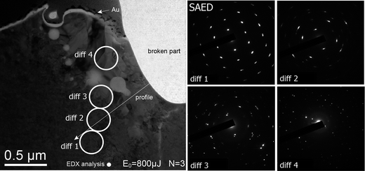 | ||
| Fig. 4 Bright Field Transmission Electron Microscopy pictures of the FIB foil cut into the monazite laser pit (E0 = 0.8 mJ per pulse, τ = 60 fs, N = 3 shots) with associated selected area electron diffraction (SAED) patterns “diff 1” to “diff 4” in which measurement areas are indicated as white circles. The natural mottled diffraction texture of the bulk crystal is again preserved and disappears in the superficial layer, while arc sparking on diffraction spots increases progressively from “diff 1” to “diff 3”. The upper layer is crystallized but contains several non-oriented grains (see Fig. 5). Their boundaries in this zone are clearly visible through the image contrasts. A part of the foil (in grey) has been broken during the FIB milling process. | ||
The previously observed structures (Fig. 2 and 3) are well underlined by clear differences such as disappearance of mottled diffraction contrasts, occurrence of voids at the lower part of the upper layer (∼650 nm deep), granular structure of this upper layer and irregular crater surface. We also notice a particular open round structure at the surface, in continuity with the voids alignment. Diffraction patterns show similar structures as observed in Fig. 3. The first acquisition (diff 1) indicates an oriented crystalline lattice and the last one (diff 4) shows the polycrystalline upper layer. However, for N = 3, the lattice is more distorted than for N = 1. Indeed, diff 2 (∼200 nm under the upper transformed layer) already shows mosaic crystal diffraction spots streaking into arcs, while this would appear much closer to the upper layer with N = 1 (<100 nm).
In order to explore the transformed areas and the mechanisms involved in the formation of the observed textures, we conducted the same TEM protocol at a smaller scale. Fig. 5 is a close up of Fig. 4 in the upper layer. We focused on a group of four nearby grains, from 50 to 100 nm in size and individual SAEDs (“diff 1” to “diff 4”) were performed on each grain. Most of them are long shaped and arranged perpendicular to the sample surface. They show identical undisturbed lattice patterns, but do not have the same orientation and are tilted to one another. The “diff 5” SAED is a combination of the four others along a mean zone axis and is similar to that obtained in Fig. 2 (“diff 4”). Hence, the 650 nm thick upper layer is made of nano-crystals slightly tilted to one another at the tens of nanometres scale.
 | ||
| Fig. 5 BF/TEM picture of a close up in the crater ablated with E0 = 0.8 mJ per pulse and N = 3 shots (Fig. 4). SAED patterns “diff 1” to “4” correspond to single grain measurements delimited by small white circles. “diff 5” is the single diffraction measurement of the 4 selected grains (large white circle). Note its similarity with “diff 4” in Fig. 2. | ||
3 Chemical composition
Energy Dispersive X-Ray analyses have been performed on the most damaged crater (E0 = 0.8 mJ per pulse, N = 3) in order to increase the probability of detecting any chemical variation. The deep unaffected sample is characterized by the white spot analysis. This spectrum (Fig. 6a) can be considered as the reference for Moacyr monazite bulk composition. The relative intensities of X-ray responses are well correlated to the known composition of this sample35 (Table 1).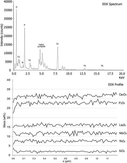 | ||
| Fig. 6 EDX chemical analyses conducted on a single spot (“EDX analysis” on Fig. 4) and following a straight line (“profile” on Fig. 4). The spectrum can be taken as a reference illustrating the pure Moacyr monazite behaviour under EDX measurements. The profile realized from a strongly irradiated area to an untouched crystal does not show any chemical variation, except with Ga (residual from FIB milling) and O (small decrease). | ||
A chemical composition profile has been made in scanning mode (STEM). The path (white arrow in Fig. 4) starts from the shocked area and covers the whole progressively disturbed-to-undisturbed zone into the clean crystal. Fig. 6b is the graphical representation of the profile, showing the main element concentration (in wt% oxides) along the profile. Appropriate correction due to the variations of sample thickness is automatically driven by the detector software. The main elements present in monazite are represented. The relative concentration of all elements is unchanged from the affected zone to the deep unaffected sample. The short fast increasing trend at the beginning of the profile results from a boundary effect, due to the fact that the starting point does not perfectly fit the sample surface.
Discussion
Influence of laser settings
Damaged structures show quite reproducible features through different laser settings such as a crystal lattice progressively strained towards the surface and a superficial transformed layer formed of recrystallized grains, round shaped voids and small cracks. For low energy and single shot (Fig. 2), these characteristics are not well developed. Nevertheless, the differences might come from the very low fluence applied. As predicted by light penetration laws,38 increasing pulse energy should tend to enlarge the irradiated volume. In consequence, the effectively ablated part of the sample is then probably larger, as indicated by the irregular crater surface at E0 = 0.8 mJ per pulse (Fig. 3) not observed for E0 = 0.1 mJ per pulse (Fig. 2). However, the nature of underlying structures is very similar from one case to the other (Fig. 2 “diff 4” and Fig. 5 “diff 5”). Increasing E0 simply leads to a clearer limit between the superficial modified layer and the deep sample on TEM pictures. The latter is in turn more affected by crystal lattice strains. This scheme is unchanged with successive shots, except that the transformed layer is locally thickened and mosaicity is extended to deeper areas of the bulk sample (Fig. 4). The presently observed structures were already reported by Seydoux-Guillaume et al.,14 yet at a lower resolution and using different laser beam focusing optics (25 mm Cassegrin objective against 50 mm coated lens), especially concerning the upper transformed layer which could not be precisely characterized. Then, it is reasonable to assess that the beam geometry does not imply any change in the damage processes, as identical structures are observed.Nature of the damaged structures
The in-depth observation of the ablated crater reveals that laser/matter interactions are a combination of mechanical and thermal effects. The latter are only detected in the superficial layer which has a structure that attests to high temperature effects. Indeed, the arrangement of long small crystals, aligned perpendicularly to the surface, is typical of a quick crystallisation. The high temperature state hypothesis is also supported by the occurrence of voids (gaseous phase occurrence). Thermal effects could then be strong enough to induce melting. Former studies, dealing with materials of different properties, have already reported this morphology after femtosecond laser ablation,16 with similar experimental conditions,17 and even similar specific features such as voids and cracks.19 In the latter, dealing with silicon samples, this resolidified layer is amorphous, attesting to high temperature ultrafast melting. In our case, monazite specific annealing properties could favour the crystallisation of small grains during rapid cooling. It has been demonstrated by Ben-Yakar et al.39 that in the femtosecond regime, the occurrence of melt would result from a fluence gradient oriented vertically and decreasing with depth, relative to the ablated layer. Our results are in agreement with this interpretation and they confirm that the spatially limited thermal effects we observe do not result from any heat diffusion process,40 but laser beam penetration depth.41 The EDX analyses bring more information, showing no modifications of composition across the irradiated layer to the intact sample (Fig. 6b). This indicates that no detectable preferential vaporization42 of elements occurs within the upper layer of the ablated crater. This seems in contradiction with our assumption that this layer has melted under laser irradiation. We may then consider that thermal effects are obviously limited to the melting of a thin layer of the sample, wherein hypothetical preferential vaporization remains under the detection limit of EDX measurement (∼1 wt%).Under this transformed layer, the typical mottled diffraction contrasts of monazite, due to irradiation damages, are perfectly preserved from high temperature annealing.36 Thus, we can conclude that no thermal effect occurs below this depth in our experiments. This is in agreement with existing experimental work.40 Considering previous interpretations,14,19 the major contribution of mechanical damage is brought via shock wave processes and stress confinement. Preliminary results obtained on synthetic quartz confirmed, by TEM characterization of shocked structures, that this interpretation would best fit the observations.43 The nature of these shock waves has been discussed in several works, and two origins are to be considered:
(i) Thermoelastic relaxation, induced by a non-regular temperature profile inside the irradiated sample, itself induced by the exponential energy absorption evolution.22 It occurs because the temperature rise is too fast for thermal diffusion in solids (≥1 ps)10 to equilibrate the irradiated volume with the surrounding material.
(ii) Recoil pressure of the plasma created from matter breakdown in the upper-lying irradiated ablated volume.44 Considering that we work far above the threshold fluence (experimentally estimated at Eth ≈ 10 μJ per pulse), the formation of a plasma45 and its very fast expansion46 induce the shock wave regime. Nevertheless, existing plasma images47 exhibit timescales of the order of nanoseconds. Then, this type of pressure wave is likely to hit back the target after thermoelastic relaxation. It is then probably at the origin of cracks (Fig. 3) observed in the superficial layer, as the other early process would rather involve plastic deformation at high temperature.
The in-depth extension of lattice distortion (Fig. 4) attests to incubation effects after cumulated laser shots.13 Nevertheless, our analysis depth is limited to the maximum FIB milling range. In consequence, the present study does not provide enough evidence of an eventual finished extension of lattice strain state, even if the cumulative mechanical process and the progressive distortion are well highlighted.
Ablation/damage mechanisms
Characterizing the damaged structures is a step forward to the complete understanding of ablation and/or damage created by ultra-short laser pulses. Nevertheless, processes involved must be identified. Several studies used molecular dynamics (MD) modelling to describe ablation processes. This method has brought evidence on the influence of pulse duration, pulse energy and number of shots on ablation behaviour.23,48,49 Moreover, it has already shown good correlations to analytical results in terms of ablation rate and influence of pulse energy.21 In the present study, structures damaged were observed by different fluences and the number of shots. We have to be sure that correlations with previous MD modelling studies are pertinent. Some parameters must then be taken into account:(i) Ablated material: Identical structures have been observed independent of the settings (Fig. 2, 3 and 4). In addition, we show in the above section that similar observations were also made in different materials using different laser settings. Moreover, MD studies report similar processes in different types of samples even if in a variable extent of occurrence.
(ii) Pulse energy: Perez and Lewis22 have shown that multiple ablation mechanisms must be considered, as a function of absorbed energy, within the same irradiated spot. Given this result that energy logically depends on sample depth, the target should always undergo all the reported ablation mechanisms at different depths independently of the initial energy setting.
(iii) Ablated volume: The presently irradiated volume is definitely larger than those considered in existing MD modelling of laser ablation. However, considering (i) and (ii), existing studies (MD simulations and direct observations) report similar phase transitions even though different sample sizes are used: ∼100![[thin space (1/6-em)]](https://www.rsc.org/images/entities/char_2009.gif) 000 atoms20 and ∼400000 atoms23 in two dimensions and even one-dimension in Povarnistyn et al.24
000 atoms20 and ∼400000 atoms23 in two dimensions and even one-dimension in Povarnistyn et al.24
For these reasons, we estimate that our analytical results can be compared to the different ablation mechanisms described in the literature. The definition of Perez and Lewis23 is particularly adapted to our FIB foil observations because variations of matter behaviour are considered as a function of sample depth in a two dimensional system. Four mechanisms are reported to take part in the ablation in regards to the energy density:
(i) Spallation illustrates matter removal under accumulation of defects leading to internal failures inside the sample. This definition fits well the progressive modification of the lattice into a mosaic crystal observed from “diff 1” to “diff 3” in Fig. 4 (arc spotting), resulting from mechanical shocks (thermoelastic wave and plasma recoil pressure), attesting to the creation of defects and incubation effects50 with single and successive shots. In this case, effects are limited to the occurrence of mosaicity in the crystal. Observed cracks also attest to a stronger mechanical effect that in some cases can lead to ablation by removal of large fragments of the target.14 In consequence, spallation probably does not damage the sample enough to start matter removal under the present ablation conditions.
(ii) Homogeneous nucleation characterizes a specific phase transition path in which matter reaches a high enough temperature state (through isochoric heating) for the following relaxation path to go through a liquid + vapour metastable region. In this region, liquid state is more stable than vapour, but local free energy peaks allow the gaseous phase to nucleate. This is also shown by Povarnistyn et al.24 whose experiments show occurrence of a gaseous phase inside a superficial liquid layer in their sample. In the present study, the morphology of the upper layer inside the crater is typical for melting and recrystallisation, while spherical voids would attest to punctual phase transition towards the vapour state. In the study by Perez and Lewis,23 these features appear much smaller (atomic scale) than our observations (∼10 nm), nevertheless, processes of coalescence after nucleation may be implied. We thus suppose that the superficial layer of the crater bottom results from homogeneous nucleation, yet not pushed forward enough to induce ablation. The open void appearing on Fig. 4 may be evidence for very small punctual ablated volumes in this regime, creating what we observe as a “porous” structure of the crater (Fig. 1).
(iii) Photomechanical fragmentation and vaporization occurs at much higher energy densities, in other words, in upper lying volumes, directly exposed to the laser beam. In our case, this would clearly correspond to the ablated volume of the sample. As the higher irradiation traces identified in our sample are probably a result of homogeneous nucleation, apparently not prone to efficiently trigger ablation, we suggest that the effectively ablated volume, overlying the crater bottom, has undergone higher irradiation state illustrated by fragmentation, vaporization or both of them. Nevertheless, the only way to highlight these mechanisms by analytical methods relies on our capacity to conduct a similar in situ study on ablation products, and confront the observations to the above mentioned processes.
According to the present study, sample damage under IR-femtosecond laser irradiation is a combination of limited thermal effects for the first time identified and correlated to existing models, and apparently not accompanied by any chemical fractionation within the analytical limits of detection of EDX, and mechanical effects. If the existing ablation models provide consequent help for underlying process identification, there is still a part of the sample that cannot be analyzed using the present protocol. Indeed, the ablated matter must be collected using a different protocol, and studied as much as possible using the same in situ characterization tools. They may bring analytical evidence of the effective ablation mechanisms in the IR-femtosecond regime. Above all this, the present conclusions cannot be directly linked to the problems of LA-ICP-MS measurement, since the produced aerosols are the only effective sample to be analyzed. In consequence, the primary importance of such a continuation study is to bring analytical interpretations to the particle generation processes. Following this, the subsequent LA-ICP-MS associated problems can probably be associated and discussed.
Conclusion
The mechanisms of infrared femtosecond laser ablation have been investigated through the in situ characterization of experimentally damaged monazite. Transmission Electron Microscopy coupled with Focused Ion Beam milled cross-sections of ablation craters performed with variable laser settings were used. Observations reveal that greatly increasing pulse energy and cumulating shots induce little changes in damaged samples. The same domains are observed without much variations of size, yet better delimited with high pulse energy ablation.Then, inside the crater, a ∼0.5 μm thick superficial layer is composed of melted and recrystallized monazite grains as well as spherical ∼10 nm voids, attesting to thermal damage. The underlying sample undergoes mechanical transformation, through accumulation of defects leading to crystal lattice distortion, probably resulting from thermoelastic relaxation and plasma recoil pressure, also at the origin of superficial cracks. This strain state progressively disappears with depth (∼2 μm). No preferential vaporization is noticed between these two domains, indicating that thermal effects are either very transient or limited. Our experimental conditions were confronted to existing analytical and theoretical studies, in order to correlate previously identified femtosecond laser induced damage mechanisms with our observations on a natural crystallized sample. Hence, the deep mechanically shocked area of the sample probably undergoes spallation, whereas the superficial thermally affected layer seems to have gone through homogeneous nucleation. Nevertheless, these mechanisms are, in our case, not enough pushed forward to initiate material removal. Photomechanical fragmentation and vaporization, specific to higher energy density areas, would rather be involved in the effective ablation, but cannot be confirmed with the present results. A following study, using protocols more adapted to the study of ablation products and similar observation tools is engaged in order to explore this hypothesis. Moreover, the main goal of such a study would be to determine the processes implicated in the generation of particles after IR-fs-laser ablation of solid samples. This will provide pertinent arguments for further interpretations of LA-ICP-MS measurements, and their related issues such as chemical fractionation.
Acknowledgements
The authors would like to thank Rémi Freydier for his motivating never-ending implication in this project, Frédéric Candaudap, Aurélie Lanzanova, Sophie Gouy and Thierry Aigouy for their availability. Christian Dominici, from CP2M, Université Paul Cézanne (Marseille) is thanked for performing FIB milling. Luc Vigroux, Pierre Marie Paul and Pierrick Leroy are thanked for their technical support and advising in femtosecond laser handling. The anonymous reviewers are thanked for their very constructive comments. This work was co-founded by CNRS, Amplitude Technologies and a PPF from the Ministry of Research.References
- J. Košler, Proc. Geol. Assoc., 2007, 118, 19–24 CrossRef.
- R. E. Russo, X. Mao, H. Liu, J. Gonzalez and S. S. Mao, Talanta, 2002, 57, 425–451 CrossRef CAS.
- F. Poitrasson, S. Chenery and T. J. Shepherd, Geochim. Cosmochim. Acta, 2000, 64, 3283–3297 CrossRef CAS.
- D. Günther and B. Hattendorf, Trends Anal. Chem., 2005, 24, 255–265 CrossRef.
- N. M. Bulgakova and A. V. Bulgakov, Appl. Phys. A: Mater. Sci. Process., 2001, 73, 199–208 CrossRef CAS.
- B. J. Fryer, S. E. Jackson and H. P. Longerich, Can. Mineral., 1995, 33, 303–312 CAS.
- T. E. Jeffries, N. J. G. Pearce, W. T. Perkins and A. Raith, Anal. Commun., 1996, 33, 35–39 RSC.
- F. Poitrasson, X. Mao, S. S. Mao, R. Freydier and R. E. Russo, Anal. Chem., 2003, 75, 6184–6190 CrossRef CAS.
- R. E. Russo, X. Mao, J. J. Gonzalez and S. S. Mao, J. Anal. At. Spectrom., 2002, 17, 1072–1075 RSC.
- D. von der Linde, K. Sokolowski-Tinten and J. Bialkowski, Appl. Surf. Sci., 1997, 109–110, 1–10 CrossRef.
- J. Krüger, W. Kautek, M. Lenzner, S. Sartania, C. Spielmann and F. Krausz, Appl. Surf. Sci., 1998, 127–129, 892–898 CrossRef.
- M. Guillermin, F. Garrelie, N. Sanner, E. Audouard and H. Soder, Appl. Surf. Sci., 2007, 253, 8075–8079 CrossRef CAS.
- J. Bonse, S. Baudach, J. Krüger, W. Kautek and M. Lenzner, Appl. Phys. A: Mater. Sci. Process., 2002, 74, 19–25 CrossRef CAS.
- A. M. Seydoux-Guillaume, R. Freydier, F. Poitrasson, F. X. D'Abzac, R. Wirth and L. Datas, Eur. J. Mineral., 2010, 22, 235–244 CrossRef CAS.
- J. Kosler, M. Wiedenbeck, R. Wirth, J. Hovorka, P. Sylvester and J. Mikova, J. Anal. At. Spectrom., 2005, 20, 402–409 RSC.
- M. Couillard, A. Borowiec, H. K. Haugen, J. S. Preston, E. M. Griswold and G. A. Botton, J. Appl. Phys., 2007, 101, 033519 CrossRef.
- A. Borowiec, M. Couillard, G. A. Botton and H. K. Haugen, Appl. Phys. A: Mater. Sci. Process., 2004, 79, 1887–1890 CAS.
- E. A. Stach, V. Radmilovic, D. Deshpande, A. Malshe, D. Alexander and D. Doerr, Appl. Phys. Lett., 2003, 83, 4420–4422 CrossRef CAS.
- E. Coyne, J. P. Magee, P. Mannion, G. M. O'Connor and T. J. Glynn, Appl. Phys. A: Mater. Sci. Process., 2005, 81, 371–378 CrossRef CAS.
- P. Lorazo, L. J. Lewis and M. Meunier, Phys. Rev. Lett., 2003, 91, 225502 CrossRef.
- N. N. Nedialkov, P. A. Atanasov, S. Amoruso, R. Bruzzese and X. Wang, Appl. Surf. Sci., 2007, 253, 7761–7766 CrossRef CAS.
- D. Perez and L. J. Lewis, Phys. Rev. Lett., 2002, 89, 255504 CrossRef.
- D. Perez and L. J. Lewis, Phys. Rev. B: Condens. Matter Mater. Phys., 2003, 67, 184102 CrossRef.
- M. E. Povarnitsyn, K. V. Khishchenko and P. R. Levashov, Appl. Surf. Sci., 2009, 255, 5120–5124 CrossRef CAS.
- R. Freydier, F. Candaudap, F. Poitrasson, A. Arbouet, B. Chatel and B. Dupré, J. Anal. At. Spectrom., 2008, 23, 702–710 RSC.
- F. X. D'Abzac, F. Poitrasson, R. Freydier and A. M. Seydoux-Guillaume, J. Anal. At. Spectrom., 2010, 25, 681–689 RSC.
- D. Strickland and G. Mourou, Opt. Commun., 1985, 56, 219–221 CrossRef.
- R. Wirth, Chem. Geol., 2009, 261, 217–229 CrossRef CAS.
- Y. Ni, J. M. Hughes and A. M. Mariano, Am. Mineral., 1995, 80, 21–26 CAS.
- J.-M. Montel, S. Foret, M. Veschambre, C. Nicollet and A. Provost, Chem. Geol., 1996, 131, 37–53 CrossRef CAS.
- R. R. Parrish, Can. J. Earth Sci., 1990, 27, 1431–1450 CrossRef CAS.
- A. Meldrum, L. A. Boatner, W. J. Weber and R. C. Ewing, Geochim. Cosmochim. Acta, 1998, 62, 2509–2520 CrossRef CAS.
- A.-M. Seydoux-Guillaume, R. Wirth, A. Deutsch and U. Scharer, Geochim. Cosmochim. Acta, 2004, 68, 2517–2527 CrossRef CAS.
- J. L. Paquette and M. Tiepolo, Chem. Geol., 2007, 240, 222–237 CrossRef CAS.
- A. M. Seydoux-Guillaume, J. L. Paquette, M. Wiedenbeck, J. M. Montel and W. Heinrich, Chem. Geol., 2002, 191, 165–181 CrossRef CAS.
- A. M. Seydoux-Guillaume, R. Wirth, L. Nasdala, M. Gottschalk, J. M. Montel and W. Heinrich, Phys. Chem. Miner., 2002, 29, 240–253 CrossRef CAS.
- A.-M. Seydoux-Guillaume, P. Goncalves, R. Wirth and A. Deutsch, Geology, 2003, 31, 973–976 CrossRef CAS.
- S. Nolte, C. Momma, H. Jacobs, A. Tünnermann, B. N. Chichkov, B. Wellegehausen and H. Welling, J. Opt. Soc. Am. B, 1997, 14, 2716–2722 CrossRef CAS.
- A. Ben-Yakar, A. Harkin, J. Ashmore, R. L. Byer and H. A. Stone, J. Phys. D: Appl. Phys., 2007, 40, 1447–1459 CrossRef CAS.
- R. Le Harzic, N. Huot, E. Audouard, C. Jonin, P. Laporte, S. Valette, A. Fraczkiewicz and R. Fortunier, Appl. Phys. Lett., 2002, 80, 3886–3888 CrossRef CAS.
- R. Hergenröder, O. Samek and V. Hommes, Mass Spectrom. Rev., 2006, 25, 551–572 CrossRef.
- C. C. Garcia, H. Lindner, A.v. Bohlen, C. Vadla and K. Niemax, J. Anal. At. Spectrom., 2008, 23, 470–478 RSC.
- C. Courtieu, F.-X. d'Abzac, J. Chmeleff, D. Guillaume and A.-M. Seydoux-Guillaume, Eur. J. Mineral., 2011, 23, 391–400 CrossRef CAS.
- S. Gacek and X. Wang, J. Appl. Phys., 2008, 104, 126101–126103 CrossRef.
- B. Le Drogoff, J. Margot, F. Vidal, S. Laville, M. Chaker, M. Sabsabi, T. W. Johnston and O. Barthelemy, Plasma Sources Sci. Technol., 2004, 13, 223–230 CrossRef CAS.
- V. Margetic, T. Ban, O. Samek, F. Leis, K. Niemax and R. Hergenröder, Czech. J. Phys., 2004, 54, 423–429 CrossRef CAS.
- X. Zeng, X. L. Mao, R. Greif and R. E. Russo, Appl. Phys. A: Mater. Sci. Process., 2005, 80, 237–241 CrossRef CAS.
- R. F. W. Herrmann, J. Gerlach and E. E. B. Campbell, Appl. Phys. A: Mater. Sci. Process., 1998, 66, 35–42 CrossRef CAS.
- D. Perez and L. J. Lewis, Appl. Phys. A: Mater. Sci. Process., 2004, 79, 987–990 CrossRef CAS.
- Y. Jee, M. F. Becker and R. M. Walser, J. Opt. Soc. Am. B, 1988, 5, 648–659 CrossRef CAS.
| This journal is © The Royal Society of Chemistry 2012 |