Enhancement of piezoelectricity via electrostatic effects on a textile platform†
Hyunjin
Kim‡
*a,
Seong Min
Kim‡
b,
Hyungbin
Son
c,
Hyeok
Kim
b,
BoongIk
Park
d,
JiYeon
Ku
e,
Jung Inn
Sohn§
e,
Kyuhyun
Im
e,
Jae Eun
Jang
f,
Jong-Jin
Park
g,
Ohyun
Kim
d,
SeungNam
Cha§
*a and
Young Jun
Park
*a
aEnergy Laboratory, Samsung Advanced Institute of Technology (SAIT), Yongin, Gyeonggi-do, Republic of Korea. E-mail: hyunjin1.kim@samsung.com; youngjunpark@samsung.com; seungnam.cha@eng.ox.ac.uk; Fax: +82 31 280 9349; Tel: +82 31 280 6782
bComputational Science Group, Samsung Advanced Institute of Technology (SAIT), Yongin, Gyeonggi-do, Republic of Korea
cSchool of Integrative Engineering, Chung-ang University, Seoul, Republic of Korea
dDepartment of Electronic and Electrical Engineering, Pohang University of Science and Technology, Pohang, Gyeongbuk, Republic of Korea
eFrontier Research Laboratory, Samsung Advanced Institute of Technology (SAIT), Yongin, Gyeonggi-do, Republic of Korea
fDaegu Gyeongbuk Institute of Science & Technology, Daegu, Republic of Korea
gPioneering Materials T/F, Samsung Advanced Institute of Technology (SAIT), Yongin, Gyeonggi-do, Republic of Korea
First published on 15th August 2012
Abstract
We have shown the enhanced piezoelectricity by electrostatic effects on a textile based platform. The electrostatic and piezoelectric effects were hybridized by integrating piezoelectric ZnO nanowires and a charged dielectric film on a wearable textile substrate. The hybrid textile nanogenerator produced an output voltage of 8 V and an output current of 2.5 μA. Using a simple AC–DC converter circuit, we operated the green organic light-emitting diode and a liquid crystal display panel using a 100 dB sonic wave.
Broader contextWith increased interest in the green energy issue, there have been a lot of efforts to harvest wasted energy and utilize it as a practical power source. One of the good candidates is mechanical energy sources such as sound waves, air or water flow, and human motion. Furthermore, integration of energy harvesting devices into textiles or clothes would have a great impact on the energy harvesting field in that it offers a good method for harvesting the vibration energy from human motion. Moreover, the demonstration of high output power by the hybrid energy generation mechanism will open the ways for enhancing the output power by integrating two energy harvesting mechanisms into one unified system. This work reports a new design of ZnO-based nanogenerators on textile substrates and offers a new route towards improving the output power of nanogenerators. By demonstrating the operation of LED and LCD, we show the potential of such generators as a practical power source for commercial electronics. |
1. Introduction
Harvesting mechanical energies such as vibrations, sound waves, air or water flow from the environment offers the possibility of realizing future self-powered systems.1–3 Piezoelectric nanogenerators based on ZnO nanowires have been extensively realized as sustainable energy sources due to their unique physical and chemical properties such as semiconductivity, piezoelectricity, and biocompatibility.4–9Furthermore, textile substrates bear one of the most promising form factors for future electronic applications due to their wide degree of freedom in shapes with flexible and stretchable characteristics. They will certainly position themselves in various applications even beyond mobile or hand-held devices, for example, patch-type health care devices and wearable energy generating sources.10,11 Thus, the integration of energy-harvesting devices into wearable textiles promises to provide novel forms of mechanical energy harvesting continuously and effectively from omnipresent sources in our daily life because the energy harvesting system can be always exposed to omnipresent mechanical energy sources, such as vibrations from people's movement or sound noises, as well as the outside wasted mechanical energy sources.12–15
In addition to the issue of utilizing various types of natural energy sources, the creation of new concepts of higher power generation is also of particular interest for operating commercial electronic devices. The integration of piezoelectric ZnO nanowires and a charged dielectric film on a textile substrate offers the hybridized effects of electrostatic and piezoelectric generators. In this regard, we have designed and fabricated a textile based energy harvester with enhanced piezopotential by electrostatic effects of the charged film.
The output power from the sound driven textile nanogenerator is significantly increased by electrostatic enhanced piezoelectric effect and large vibration displacement of textile substrates. The highest peak output voltage and output current of the generator were recorded to be up to 8 V and 2.5 μA, respectively, at a sonic input power of 100 dB. Using our hybrid nanogenerator, we operated a homemade green organic light-emitting diode and a 9 cm × 3 cm liquid crystal display panel, demonstrating its new concept of high power generation as a practical power source. Our findings provide a viable way to create a new wide range of self-powered systems with a high power requirement.
2. Experimental details
The textile substrate was formed by Au coated woven artificial fibers made from polyester. On top of the Au layer, ZnO nanowires were hydrothermally grown. To uniformly grow ZnO NWs on large-area textile substrates, the seed layers were grown after dipping the textile substrate in a 0.02 M zinc acetate dihydrate solution (zinc acetate dehydrate and ethanol) for 3 minutes and then baking it on a hot plate at 200 °C for 5 minutes. After repeating the process four times, the growth of ZnO NWs followed. A zinc nitrate hexahydrate (98%, Aldrich) and hexamethylenetetramine (99%, Aldrich) solution was prepared in deionized water at a 25 mM concentration. Then, the Au-coated textile substrates were suspended upside down in a glass bottle that was filled with the aqueous solution, and the glass bottle was heated in an oven at 90 °C for 5 hours. After the growth reaction, the as-grown ZnO NWs were air-dried. A thin, self-adhesive 40 μm thick polyethylene (PE) film16 was then placed on top of the ZnO NWs. Another Au-coated textile substrate was placed on the charged PE layer as the top electrode.3. Results and discussion
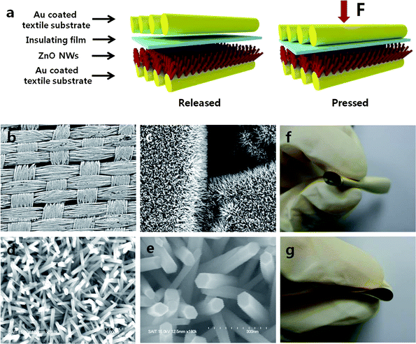
The schematic of the textile-based hybrid nanogenerator is shown in Fig. 1a, and 1b displays a field emission scanning electron microscopy (FE-SEM) image of the ZnO NWs, which are uniformly grown on the textile substrate (∼10 cm2), showing full coverage of woven fibers (Fig. 1c). Fig. 1d and e present high-resolution SEM images of the individual ZnO wires, which were approximately 100 nm in diameter and 1 μm in length. Photographic images of the rolled up and folded textile substrate are shown in Fig. 1f and g. Other than certain plastic substrates, textiles are one of the very few materials that can be fully folded and rolled without forming deep cracks and any limits in the bending curvature, allowing a free form factor. | ||
| Fig. 1 Schematics and SEM images of a textile electrostatic–piezoelectric hybrid nanogenerator. (a) Schematics of a textile electrostatic–piezoelectric hybrid nanogenerator, (b and c) large-area SEM images of ZnO NWs grown on a textile substrate, (d and e) high-resolution SEM images of ZnO NWs grown on a textile substrate, and (f and g) photographic images of a textile substrate after its rolling and folding. | ||
The hybrid electrostatic and piezoelectric nanogenerators exhibited significantly enhanced output power, which resulted from the coupled effect of two generation mechanisms: piezoelectric and electrostatic effects. The PE film had a tendency of being negatively charged when in contact with relatively positively charged triboelectric materials (i.e., Au and ZnO). The surface charge density of the PE film was up to −2 × 10⁻⁴ C m−2, as converted from the surface potential measurements made by an electrostatic voltmeter (Treck 542A-1) (Fig. S1†). To systematically investigate the mechanism of energy generation of our hybrid nanogenerator, which was made using a textile with a PE film and ZnO NWs, we examined the electrostatic effect of the PE film and the piezoelectric effect of ZnO NWs, separately.
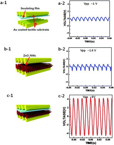
In our structure, the electrostatic energy was generated from the changes in the electrostatic capacitance between the negatively charged PE film and the Au-coated textile when the distance between the PE film and the textile substrate changed due to their vibrations.17–20 The variation in capacitance led to the alternating current flow on the outer circuit and generated an AC output voltage (Fig. 2a-1). Upon applying a sinusoidal sound input at 100 dB and 100 Hz, the peak-to-peak AC output voltage was measured as ∼1 V, as shown in Fig. 2a-2. On the other hand, the energy for the piezoelectric component of the nanogenerator was generated from the potential gradient that was created within the ZnO NWs in response to external stress or strain. A Schottky barrier was formed between the ZnO NWs and the Au-coated textile electrode, inducing generation of AC voltage/current on the external circuit due to the alternating sonic pressure on the ZnO NWs (Fig. 2b-1). The output voltage (with the same power and frequency as the electrostatic case) was measured as 1.6 V (Fig. 2b-2). When the electrostatic and piezoelectric components were combined, as schematically shown in Fig. 2c-1, the generator produced a much higher peak-to-peak output voltage of up to 8 V using the same source of sonic wave input (Fig. 2c-2). This result indicated that, in addition to the electrostatic and piezoelectric effects, the coupling effect between the ZnO NWs and the charged PE film effectively contributed to enhancement of the output power of the hybrid nanogenerator.
 | ||
| Fig. 2 Schematics of textile nanogenerators, output voltages, calculated electron concentration and piezoelectric potential. Schematics of (a-1) a textile electrostatic generator, (b-1) a textile ZnO piezoelectric nanogenerator, and (c-1) a textile electrostatic–piezoelectric hybrid nanogenerator. The output voltages of (a-2) a textile electrostatic generator, (b-2) a textile ZnO piezoelectric nanogenerator and (c-2) a textile electrostatic–piezoelectric hybrid nanogenerator generated by a sonic wave at 100 dB and 100 Hz frequency. | ||
The piezoelectric potential generated in the ZnO nanowires is due to the piezoelectric polarization, i.e. dipolar formation caused by the deformation. However, because of the semiconducting properties of ZnO nanowires, the free charges (free electrons) in the nanowires screen the piezoelectric polarization and reduce the piezoelectric potential. Thus, the piezoelectric potential of ZnO nanowires can be increased by eliminating the screening effect of the free carriers. In our device schematics, the screening effect of free carriers is reduced by depleting the free carriers of the nanowires by a PE film and this leads to the enhanced piezoelectric effects of the ZnO nanowires.21
Finite element analyses (FEA, COMSOL) were used to numerically solve potential and electron distribution of our hybrid system (see ESI†). The as-grown ZnO NWs were assumed to have a donor concentration of Nd = ∼1017 cm−3, and the bottom of the NWs were affixed and electrically grounded.15 The piezoelectric potentials were calculated under a constant stress (Tz of −1.4 × 10⁸ Pa) with and without the surface charge density of the PE film. The negative surface charges on the PE film cause the redistribution of electrons within the NWs, such that the electron concentration in the upper part of each NW, close to the film, is dramatically reduced to near zero (Fig. 3a and c). Thus, as shown in Fig. 3b, the piezoelectric potential of the ZnO NWs is greatly enhanced due to the formation of the depletion region. Therefore, in addition to individual electrostatic and piezoelectric effects, this coupled effect of the enhanced piezoelectric potential contributes to the high output power from the hybrid generator.
 | ||
| Fig. 3 Simulation results of electron concentration and piezoelectric potential: (a) the calculated electron concentration along the z-axis of the ZnO NW with and without the surface charge of the PE film under a constant external stress (Tz of −1.4 × 10⁸ Pa) from the top, (b) the calculated piezoelectric potential along the z-axis of the ZnO NW with and without the surface charge of the PE film with same external stress, and (c) schematics of the calculated electron concentrations of the ZnO NW with and without the negatively charged PE film. | ||
Another advantage of the textile substrate is its higher efficiency when compared to any other solid or flexible substrates in coupling external sonic waves into its own vibrational motion.
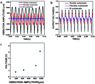
The vibrational amplitudes of three different substrates, Si, flexible polyethersulfone (PES), and textile, were measured under the same input sonic power of 100 dB at 100 Hz using a laser optical vibrometer (Keyence, LK-H025). For the Si, flexible PES, and textile substrates, the vibrational amplitudes were 30 μm, 960 μm and 2250 μm, respectively (Fig. 4a). Subsequently, the correlation between the vibrational amplitude and output voltage from the generator was compared. To do this, we fabricated ZnO piezoelectric nanogenerators on Si, flexible PES and textile substrates without any PE film inserted; the output voltages from the nanogenerators made from Au-coated Si substrates, flexible PES, and textile substrates were 0.3 V (peak-to-peak), 0.7 V (peak-to-peak), and 1.6 V (peak-to-peak), respectively, as shown in Fig. 4b. A higher output voltage was generated from the textile based nanogenerator when compared to the output from the nanogenerator made from other substrates. The higher output voltage from the textile nanogenerator is attributed to the large vibrational amplitude of the textile substrate to which the sonic energy is well transferred. Finally, the vibrational amplitude vs. the output voltage from the hybrid nanogenerator (with PE film inserted) is also plotted in Fig. 4c after changing the sonic input power. Fig. 4c and Fig. S2a and b† showed a significant increase in output voltage from the hybrid nanogenerator when the vibrational amplitudes were increased.
 | ||
| Fig. 4 Vibration amplitude and output voltage measurements: (a) comparison of the vibration amplitude of the Si, flexible PES, and textile substrates that were vibrated by a sonic wave at 100 dB and 100 Hz, (b) comparison of the output voltage of the Si, flexible PES, and textile piezoelectric nanogenerators and (c) output voltage vs. vibration amplitude of the textile hybrid nanogenerator that was driven by different input sonic powers. | ||
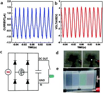
The 10 cm2 textile hybrid nanogenerator was operated by a 100 dB sound wave with a 100 Hz frequency. The peak-to-peak AC short-circuit current and open-circuit voltage from the textile hybrid nanogenerator were 2.5 μA and 8 V, respectively, as shown in Fig. 5a and b. The high output voltage enables an efficient conversion of AC to DC with a simple full wave rectifier and a filtering capacitor, as shown in Fig. 5c. With such high output voltage and current, the textile hybrid nanogenerator is capable of directly driving some practical electronic devices such as organic light emitting diode (OLED) and liquid crystal display (LCD) panels. To demonstrate such capability, a green OLED (2 mm × 2 mm) and a 9 cm × 3 cm reflective LCD panel were driven by the nanogenerator. To drive the OLED, a 20 μF capacitor was first charged to about 3 V by applying a sonic wave of 100 dB at 100 Hz to the hybrid nanogenerator for 120 s. When the OLED in series with a 200 kΩ resistor was connected to the charged capacitor, a bright green light was turned on momentarily as shown in Fig. 5d and the ESI movie 1.† The LCD panel was driven using the same driving conditions and the RGB patterns on the LCD panel were turned on for several seconds (Fig. 5e and ESI movie 2†). We have demonstrated by turning on an OLED and a LCD panel by sound generation that our hybrid nanogenerator has the potential as a practical power source for commercial electronics.
 | ||
| Fig. 5 OLED and LCD operated by a sound-driven textile hybrid nanogenerator. (a) The peak-to-peak short circuit current, (b) the open circuit voltage from the large-area textile electrostatic–piezoelectric hybrid nanogenerator, (c) the circuit of the full wave rectifying bridge, (d) OLED turned on by the sound-driven textile electrostatic–piezoelectric hybrid nanogenerator after the full wave rectifying bridge and (e) an LCD panel operated by the sound-driven textile hybrid nanogenerator. | ||
4. Conclusions
In summary, a hybrid nanogenerator was demonstrated on a fully textile substrate for the first time, by integrating a charged dielectric layer and piezoelectric ZnO NWs between textile substrates. The observation of a high output voltage from the hybrid nanogenerator was due to the synergic effects of electrostatics and enhanced piezoelectricity of ZnO NWs by the surface charge of the inserted PE film. Additionally, large mechanical vibrations driven by sonic waves were observed on the textile substrate and contributed to a higher output power. The maximum output peak voltage and current reached 8 V and 2.5 μA, respectively, using sonic waves at 100 dB and 100 Hz. This work demonstrated that output voltage and current of a textile hybrid nanogenerator are sufficient to drive OLED and LCD panels and showed the textile hybrid nanogenerator to be an attractive power source for self-powered systems.Acknowledgements
H.-J. Kim carried out experimental design, device fabrication and data analyses; S.M. Kim and Hyeok Kim carried out simulations and data analyses; H.B. Son, B. Park, J. Ku, and J. I. Sohn carried out the device fabrication and measurement; K. H. Lim fabricated the OLED; J. E. Jang fabricated the LCD panel; J. J. Park designed the textile substrate; H.-J. Kim, S. Cha and Y.J. Park planned and designed the work and provided experimental guidance; O. Kim designed the work and provided experimental guidance.This work was supported by a grant (2011-0031659) from the Center for Advanced Soft Electronics under the Global Frontier Research Program of the Ministry of Education, Science and Technology, Korea.
Notes and references
- M. Lee, J. Bae, J. Lee, C.-S. Lee, S. Hong and Z. Lin Wang, Energy Environ. Sci., 2011, 4, 3359–3363 CAS.
- C. Sun, J. Shi, D. J. Bayerl and X. Wang, Energy Environ. Sci., 2011, 4, 4508–4512 CAS.
- Y. Zhang, Y. Yang and Z. L. Wang, Energy Environ. Sci., 2012, 5, 6850–6856 CAS.
- R. Yang, Y. Qin, C. Li, G. Zhu and Z. L. Wang, Nano Lett., 2009, 9, 1201 CrossRef CAS.
- S. N. Cha, J. S. Seo, S. M. Kim, H. J. Kim, Y. J. Park, S. W. Kim and J. M. Kim, Adv. Mater., 2010, 22, 4726 CrossRef CAS.
- X. Wang, J. Song, J. Liu and Z. L. Wang, Science, 2007, 316, 102 CrossRef CAS.
- Z. L. Wang and J. H. Song, Science, 2006, 312, 242 CrossRef CAS.
- Y. Hu, Y. Zhang, C. Xu, G. Zhu and Z. L. Wang, Nano Lett., 2010, 737, 5025 CrossRef.
- S. Xu, Y. Qin, C. Xu, Y. Wei, R. Yang and Z. L. Wang, Nat. Nanotechnol., 2010, 5, 366 CrossRef CAS.
- Y. Qi and M. C. McAlpine, Energy Environ. Sci., 2010, 3, 1275–1285 CAS.
- K. Jost, C. R. Perez, J. K. McDonough, V. Presser, M. Heon, G. Dion and Y. Gogotsi, Energy Environ. Sci., 2011, 4, 5060–5067 CAS.
- M. Hamed, R. Forchheimer and I. Olle, Nat. Mater., 2007, 6, 356 Search PubMed.
- Y. Qin, X. Wang and Z. L. Wang, Nature, 2008, 451, 809 CrossRef CAS.
- T. Sekitani, Y. Noguchi, K. Hata, T. Fukushima, T. Aida and T. Someya, Science, 2008, 321, 1468 CrossRef CAS.
- K. Cherenack, C. Zysset, T. Kinkeldei, N. Münzenrieder and G. Tröster, Adv. Mater., 2010, 22, 5178 CrossRef CAS.
- PE film is self-adhesive film composed of 40um thin polyethylene film and its surface tends to be negatively charged due to strong negative triboelectric properties.
- S. P. Beeby, M. J. Tudor and N. M. White, Meas. Sci. Technol., 2006, 17, R175 CrossRef CAS.
- J. Boland, Y. H. Chao, Y. Suzuki, Y. C. Tai, Micro Electret Power Generator, IEEE, 2003, p. 538 Search PubMed.
- B. C. Yen and J. H. Lang, IEEE Transactions on Circuits and Systems I: Regular Papers, 2006, vol. 53, p. 288 Search PubMed.
- Y. Gao and Z. L. Wang, Nano Lett., 2009, 9, 1103 CrossRef CAS.
- J. I. Sohn, S. N. Cha, B. G. Song, S. M. Kim, H. J. Kim, J. Y. Ku, S. Lee, Z. L. Wang, B. L. Choi, J. M. Kim, Adv. Mat., submitted Search PubMed.
Footnotes |
| † Electronic supplementary information (ESI) available. See DOI: 10.1039/c2ee22744d |
| ‡ These authors contributed equally to this work. |
| § Current address: Department of Electrical Engineering Science, Oxford University, Oxford, UK. |
| This journal is © The Royal Society of Chemistry 2012 |
