Towards an objective method to compare energy storage technologies: development and validation of a model to determine the upper boundary of revenue available from electrical price arbitrage
Edward
Barbour
*a,
I. A. Grant
Wilson
*b,
Ian G.
Bryden
a,
Peter G.
McGregor
c,
Paul A.
Mulheran
b and
Peter J.
Hall
b
aInstitute for Energy Systems, The University of Edinburgh, Edinburgh, UK
bDepartment of Chemical and Process Engineering, The University of Strathclyde, Glasgow, UK. E-mail: grant@myoto.com
cFraser of Allander Institute, The University of Strathclyde, Glasgow, UK
First published on 5th December 2011
Abstract
This article proposes a methodology to calculate the upper boundary of the revenue available from the storage and time-shifting of electrical energy. The inputs to the mathematical model are a discrete time-series of the market index prices over a particular period of interest, and also specific energy storage device parameters. By using a Monte Carlo based optimisation method, the upper boundary of the revenue from time-shifting energy is determined. The method is explained and validated by showing that it finds the optimum solution that is the upper boundary for time-shifting revenue. In other words, a storage operator could never derive more revenue than this value from time-shifting alone and calculating this upper-boundary gives a reference value to compare the efficacy of other methods of estimation. The user defined storage device parameters include: fixed efficiencies for charging and discharging (%), the maximum capacity of the storage device (kWh), the charging and discharging power limits (kW), and the inclusion of an additional time-dependent efficiency that models the self-discharge of storage devices (% loss per hour). The combination of these parameters enables this method to give an objective comparison between different storage devices in terms of maximum arbitrage revenue. The output of the model provides not only a single value of the upper boundary revenue, but also the corresponding charging/discharging schedule.
1 Introduction
Recently there has been greater global interest towards energy storage in order to reduce the perceived risks associated with greater penetration of non-dispatchable renewable generation (e.g. not available on demand) within electrical networks at both the distribution and transmission level. Although storage at many scales is an internationally important active area of research and development on a technical level, there is a need for greater understanding of the economic and market drivers for widespread energy storage deployment.The methodology presented in this article is able to compare energy storage devices with access to spot market prices. The data used in testing the model is the historical UK market index price for electricity (the electrical spot price data).
Table 1 shows the characteristics of the four pumped storage schemes in the UK, with currently (2011) an additional ∼60 GWh (600 MW power) of pumped storage development in the Scottish planning system.1
| Name | Storage (GWh) | Output (MW) | Location | Year |
|---|---|---|---|---|
| Ffestiniog | ∼1.3 | 360 | Wales | 1963 |
| Ben Cruachan | ∼10 | 440 | Scotland | 1966 |
| Foyers | ∼6.3 | 300 | Scotland | 1974 |
| Dinorwig | ∼10.1 | 1728 | Wales | 1983 |
Fig. 1 shows the historical level of electrical energy output from pumped storage facilities in the UK from 1970–2009, from a built capacity of 2788 MW. During this time Foyers and Dinorwig pumped storage schemes were comissioned, and there was also an incremental increase in Dinorwig's energy storage capacity in 2007 from ∼9.4 GWh to ∼10.1 GWh (1728 MW power). The contribution from pumped storage has only recently climbed above 1% of the total net electricity supplied from the major UK power producers and this is thought to be partly due to the increase in the capacity of Dinorwig mentioned previously, coupled with a more favourable price environment for electrical energy arbitrage from 2006–2008. Other recent interest in bulk electrical energy storage includes the discontinued Regenesys flow battery project at Little Barford in 2002 that had a design of 120 MWh with 12 MW power.
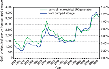 | ||
| Fig. 1 GWh of electrical energy from UK pumped storage schemes 1970–2009, and expressed as a % of the net electricity supplied by major power producers.2 | ||
It is not known with a high degree of certainty how the expected increase in renewable energy generation (large scale > microgen scale) will impact the price volatility of electricity markets, but in terms of long-term price forecasting of UK electrical energy prices there is a view that they will become more volatile in the future, as the contribution from renewable energy sources increases.3–5 The economic argument for storage should improve if the revenues derived from daily arbitrage of energy were to increase. It is notable that in the United Kingdom the level of energy traded through the power exchanges is currently less than 3% of all electrical energy traded,6 as over 90% of electrical energy is traded through the forward market in confidential bilateral contracts between generators and suppliers.7 Although the power exchange market may seem small, it is crucial not only as a market of last resort but also as the market where the spot price of electricity is discovered, which then influences the prices in the forward and ancillary markets.
Bulk electrical energy storage is seen by the authors as providing a service to address the mismatch between supply and demand of electricity, and is viewed as a complementary technology to greater market interconnectivity and also demand side management. Specifically, it is a useful tool to match the temporal disparity between supply and demand. This function has historically been undertaken by using the “store” of electrical energy contained within fuelsi.e. by increasing or decreasing dispatchable generation, and thus matching supply to demand. The overwhelming choice for these “stores” of electrical energy in the UK continues to be fossil fuels.8
Although it is erroneous to directly compare electrical energy prices to other types of commodity prices, due to the unique nature of electrical energy (it has generally been used when it is produced as it has been uneconomic to store in bulk), it is interesting to note that the price volatility of electrical energy is much greater than that of other types of traded goods or services, with daily price swings of greater than 100% being commonplace (see Fig. 3). Papers by Weron9 and Madalena et al.10 give a comprehensive overview of the stylised facts of energy prices, which include inter alia; high volatility, seasonality of prices, the inclusion of price spikes and also mean reversion to a daily pattern. Weron11 (pp25) captures this succinctly, “One of the most pronounced features of electricity markets are the abrupt and generally unanticipated extreme changes in the spot prices known as jumps or spikes. Within a very short period of time, the system price can increase substantially and then drop back to the previous level.”
Several studies have looked at quantifying the revenues available from time-shifting energy, including Mokrian and Stephen12 that looked at the optimisation of storage over a 24-hour period, by comparing a linear, a multi-stage stochastic and a dynamic method of optimisation. Crampes and Moreaux13 looked at the Nash equilibrium of differing market factors, but only considered this using an off-peak and peak price. Figueiredo and Flynn14 looked at the costs as well as the revenue element of arbitrage, but used a fixed round trip efficiency of 80%. Barbour and Bryden15 illustrated how the required properties (capacity, self-discharge, fixed input/output efficiencies and charging and discharging power limits) of a storage system change depending on the form of the time-shifted output required, and although the focus is mainly on tidal current energy conversion, this approach is applicable to any form of energy conversion.
It is acknowledged that this problem (calculating the upper boundary of the revenue that a storage device could derive using price differentials within electrical spot market data) can be approached with other programming methods e.g. Connolly et al.16 The method presented in this article is a novel approach that not only calculates the maximum revenue for long user defined periods of interest (from days to years), but also includes a time dependent efficiency loss that aims to model self-discharge. The introduction of a time-dependent variable provides another layer of complexity that then requires a non-trivial solution.
2 UK market index price data analysis
In the UK, the market index price is a discrete time-series of price data, which is a post-hoc weighted average of the trades through the power exchanges for a specific 30 min period. Historical market index price data from the UK power exchanges are used as the price input to the model for the purposes of this article, in order to remove the errors associated with price forecasting and due to the availability and robustness of the price data set. The data is freely available for the UK, is robust after 200517 and can therefore be used by other groups to compare or contrast different methods of determining the revenue available from the storage and time-shifting of electrical energy. Historical price data is the equivalent of perfect forecasting and by this reasoning, using historical price data provides the upper boundary of the arbitrage revenue available to a given storage device for that particular timeframe i.e. a storage operator will never be able to gain more than the upper boundary revenue deduced here via arbitrage alone. This is independent of forecasting ability, but better forecasting should allow an ever closer approach to this upper boundary revenue figure.Fig. 2 illustrates the 2009 prices as a ‘heat map’. The different colours illustrate how the price changes throughout the day over the year 2009; it is interesting to note that the time of the highest daily price does seem to vary significantly from season to season, with the winter peak prices in the early evening 17:00 to 20:00 timeframe and the summer peak prices scattered throughout the daytime. The lowest prices do not show this seasonal variation to the same degree, and are likely to happen between the hours of 03:00 and 06:00 throughout the year (also see Fig. 4). It is this variation in the price of electrical energy that provides opportunities for energy storage device operators to exploit price differentials. The percentage figures used throughout this article for sale prices are expressed in terms of a percentage increase of the initial buy price, i.e. if the sale price is twice the buy price, it is expressed as a 100% increase relative to the buy price.
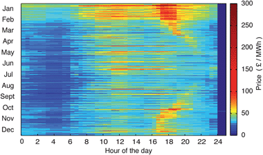 | ||
| Fig. 2 ‘Heat map’ illustrating the pattern of daily price variations throughout 2009. The figure is corrected for daylight savings, with day 88 being 23 h long and day 298 being 25 h long. | ||
Fig. 3 is a histogram of the number of days plotted against the percentage increase in price within that day for 2009. The percentage increase is calculated by determining the greatest possible change in price in each day (starting at 00:00 and finishing at 24:00). This may not, however, be the same as the difference between the absolute highest and lowest prices in a given day if the highest price occurs before the lowest price.
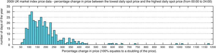 | ||
| Fig. 3 2009 UK market index price data - percentage price increase between the lowest daily spot price and the highest daily spot price. The % price increase is calculated relative to the buy price, therefore 0% in this graph would be: sell price = buy price = no change in price. | ||
The period starting point was investigated to determine whether starting at 00:30, 01:00 etc. would cause a difference in the calculated percentage price increases. By changing the start period incrementally from 00:00 to 24:00 it was found that the average change in price for the year was ∼ 1% between time period starts from 00:00 and 05:00, and that the 00:00 start time gave the highest yearly average change in price, throughout a range of differing years. In contrast, using a start time between 05:00–21:00 gave a significantly reduced average figure for the price increase. The price histograms presented here use a 24-hour period that begins at 00:00 and ends at 24:00 (Fig. 3 & 4). The model algorithm, however, can be based on longer timeframes and is unaffected by a daily start point.
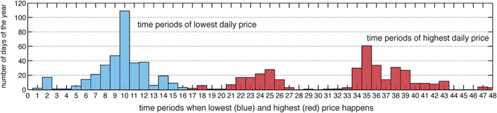 | ||
| Fig. 4 2009 UK market index price data – 30-minute time-period within the day when the lowest and highest price happened. | ||
It should be noted that the percentage price increase (as a measure of the ability to cover the costs of the efficiency losses in the system) is a relative rather than an absolute measure. A higher absolute price differential will afford a storage operator a greater absolute revenue e.g. buying at £25/MWh and selling at £50/MWh has the same percentage price change as buying at £100/MWh and selling at £200/MWh, but the latter will, ceteris paribus, afford the storage operator greater increased revenue than the former.
The minimum percentage increase in price within any day of 2009 was 52%. This means that each and every day there was the opportunity to sell energy for at least 52% more than the buying price, i.e. there was a daily opportunity for a storage system that is more than 66% efficient (=100/(1 + 0.52)%) to cover the cost of the round trip energy efficiency losses. Fig. 4 shows the time periods within a day when the lowest and the highest prices occur.
Fig. 5 shows the cumulative distribution function for the price increase available in the next 24 h, for every period of 2009. It can be seen from the figure, that the median price increase is 75%, meaning that for a ½ hour period of the year picked at random, there will be a 50% chance that the price increase available in the next 24 h is greater than 75%.
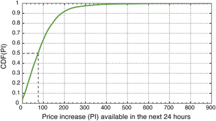 | ||
| Fig. 5 A cumulative distribution function (CDF) to show the price increase (PI) available for every period in the year. The value of 0% means there is no price higher than the current price over the next 24 h. | ||
Having established that in the UK market there exists the daily opportunity for a storage system of greater than 66% efficiency to cover the financial penalty from the round trip losses; a model to determine the maximum revenue available to storage systems (with user defined properties) is introduced.
3 Model assumptions
In calculating the upper boundary of the revenue available to the storage system the following assumptions are made:The storage device is a price taker and does not influence the overall spot market price
This is likely to be a good approximation for any individual grid-connected small storage device. However, as the overall level of storage increases on a network, it is likely to have a smoothing effect on market index prices, as bulk storage generally acts to create extra demand when prices are low, and provide supply when prices are higher. It is expected that greater levels of dispatchable bulk storage will begin to influence the price spread behind the time-shifting revenue stream. However, this is not thought likely to be an issue in the UK market in the short to medium term.The time taken to change the charging or discharging rate within the power limits of the storage device is negligible compared to the spot price period
The validity of this assumption depends on the device in question, but storage devices generally have much higher ramp rates than conventional generators. Even Pumped Hydro which is usually regarded as having a slow response for a storage medium can often increase its ramp rate by several hundreds of MW per min.The storage device is not subject to network capacity constraints
Any network constraint would reduce the ability of the storage device to operate – therefore reducing the potential revenue. The revenue would therefore be expected to be less than the upper boundary figure calculated for zero network constraints.The device parameters are assumed to have constant values
The charging/discharging efficiencies do not change with the charging rate, and the time constant describing the self-discharge remains constant in this model. An interesting approach outlined in Darling et al.18 regarding the evaluation of levelised costs based on distributions of assumed values may be a feasible approach for future work in order to get confidence intervals on the upper boundary estimation associated with uncertainty in device parameters.Price forecasting
This article makes no attempt to deal with the area of price forecasting, which is a large, complex and heavily researched field of work in its own right in both the public and private spheres. One potential advantage of this is that the maximum revenue deduced here is independent of forecasting ability.The aims of this article are two-fold; to add to the debate around the level of revenue achievable from the storage and time-shifting of energy by calculating the upper boundary of revenue a device could expect to generate using spot markets, and to stimulate thought in other groups and researchers interested in the financial value of energy storage.
The use of historical price data and the methodology proposed here calculates the maximum possible revenue that could have been attained with historical market conditions. If this information is combined with lifetime costs of the storage devices (O&M, installation cost, connection costs etc…), this should allow for a more informed decision of whether or not a given storage device is likely to provide a desired level of profitability.
4 Principles of the model
The model is based on the price differentials that are required to cover the round trip energy losses, which are a factor for any storage device. For example, if an energy storage device has a total round trip efficiency of 33% then the sale price would need to be at least treble the purchase (buy) price just to cover the efficiency losses, an increase of 300%.The ability of any storage system to produce a positive revenue stream from the time-shifting of energy will depend on the relative price variation of bought and sold electrical energy and the round trip efficiency of the system (composed of both fixed and time dependent efficiencies). This is true irrespective of the separation in time between buying and selling.
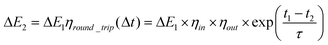
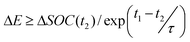
The model is able to consider two different forms of efficiency losses: those that are time dependent, and those that are not. It is assumed that there will be a fixed penalty for transferring energy into and out of the store, and once the energy has been transferred ‘in store’ there will be a loss rate dependent on the amount of stored energy, as described by the exponential term in eqn (1). This time dependent loss of energy models the self-discharge of the storage device. As such, the energy output ΔE2 from the store (at time period t2), after an amount ΔE1 has been input (at time period t1) will be given by eqn (1) below.
 | (1) |
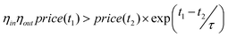
In eqn (1), ηin is the fixed efficiency of the transfer into the store (charging efficiency), ηout is the fixed efficiency of the transfer out of the store (discharging efficiency), and the time dependent self-discharge rate from the store is:
| d(SOC)/dt = −SOC(t)/τ |
The combination of all 3 of these losses yields the round trip efficiency of the storage process between t1 and t2, ηround_trip(Δt), where Δt = t1 - t2.
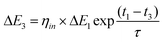
Similarly, the change in energy contained in the store ΔE3, at an intermediate period t3, where t1 < t3 < t2, will be given by eqn (2).
 | (2) |
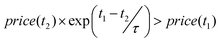
Therefore, if the price of electricity at t2 is more than a factor of 1/ηround_trip(Δt) than the price at t1, then buying energy at t1 (to store) and selling at t2 will give a positive addition to the overall revenue available to the storage operator. This is the governing driver of the model; to establish whether a potential time-shifting of energy will indeed increase the overall revenue, after the fixed and time dependent losses have been taken into account.
The Monte Carlo optimisation algorithm searches the space of feasible solutions finding the solution which corresponds to the global maximum in the revenue. The detailed operation of the method is outlined in the Appendix. A flowchart illustrating the operation can be seen in Fig. 6. A feasible solution is defined as a schedule of operation of the storage system, which could in principle be implemented – i.e. a solution that is physically realisable and does not violate any of the constraints.
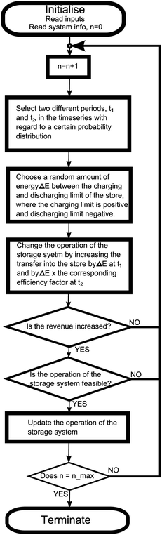 | ||
| Fig. 6 A flowchart depicting the action of the optimisation algorithm. | ||
Once the solution reaches a point where the revenue has stopped increasing, the solution is considered to be optimal. As a non-deterministic algorithm, the path to get to the optimal solution will differ from one run to the next, but (with enough iterations) the same final optimal solution will be attained. Fig. 7 shows the convergence of the algorithm on the upper boundary of arbitrage revenue.
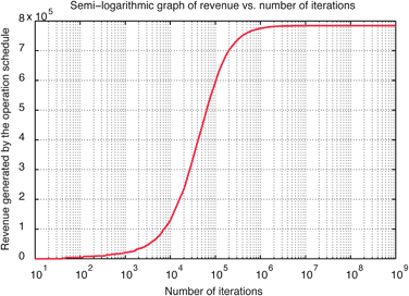 | ||
| Fig. 7 A graph illustrating the approach of the algorithm to the optimal solution (for PHS 20MW power for 2009 – Table 2). The time window is a year (17520 ½ hour periods) and the maximum number of iterations is 109. The graph plots Revenue achieved by the operation of the system vs. Log10(iteration number). | ||
The code for the model was initially written and tested in MATLAB, and was ported to FORTRAN95 for speed. Implemented in FORTRAN95, the algorithm takes around 5 min to run 108 iterations on a 2.99GHz processor (Dell Optiplex 760, Intel Core Duo CPU E8400, 2.99GHz). Using the High Performance Computing facilities at Strathclyde and Edinburgh Universities allows access to far greater computing power, giving the potential to run the algorithm for different types of storage devices with different fixed and time dependent loss characteristics over much longer timeframes e.g. from pumped hydro systems having significant fixed losses and very little time dependent losses,18,19 to flywheels with higher self discharge rates but relatively small fixed losses.20 The maximum feasible revenue (the upper boundary that the storage system could have generated over the time period in question) is attained by following the optimal schedule of operation for the storage system (also an output of the algorithm.)
5 Model validation
In order to validate the model, some test scenarios that have intuitive solutions for the optimum schedule of operation of the storage system are considered. To simplify the situation, an artificial input price regime is used (referred to as the test price). The scenarios and model results are as follows:Fig. 8(a) Scenario 1: The time-series test price is a square wave varying between £50/MWh and £100/MWh. This is run with an infinite capacity 100% efficient storage system, with charging and discharging limits of 20MW (PLI, PLO = 20 MW). Therefore, we would expect the optimised result to output a schedule that charged at 20MW for the first 12 h, then discharged at 20MW for the following 12 h, and then repeated. The figure of the model results is an excellent fit with the expected schedule.
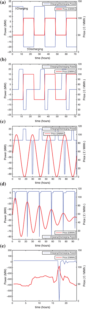 | ||
| Fig. 8 Results for optimisation of each of the 5 test cases described in the model validation section. (a) Scenario 1, (b) Scenario 2, (c) Scenario 3, (d) Scenario 4 and (e) Scenario 5. The figures all show the model’s output schedule for energy transfer to and from the store with the given price input and constraints specified for each case. | ||
Fig. 8(b) Scenario 2: shows the model's output schedule for charging or discharging the store when the time constant of the store is 12 h (i.e. the store loses 50% of its energy every 8.3 h). The charging/discharging limits, infinite capacity and input test price are the same as the previous scenario. The output is as expected; a square wave which aims to minimise the time over which energy is stored.
Fig. 8(c) Scenario 3: The test price used is a sine wave with a period of 24 h and amplitude of £50/MWh, centred on £50/MWh (varying from £0 to £100/MWh). The storage system has a fixed round trip efficiency of 10%, a charging limit of 20MW, a discharging limit of 60MW, and an infinite storage capacity that has no time dependent losses. The figure shows the model's output schedule for charging or discharging the store, along with the corresponding electricity test price. As would be expected, the model only stores and releases energy when energy can be bought for less than 10% of the selling price.
Fig. 8(d) Scenario 4: The test price is a decaying sine wave test price, with a period of 18 h centred on £50/MWh (price(t) = 50 + (50-t/2)sin(πt/9)). The storage system has infinite capacity, no losses, a charging limit of 5MW, and an unconstrained discharging limit. The algorithm finds the optimum result where the storage operator charges at the maximum rate until the highest price, at which point all of the accumulated energy is sold. When a further price increase becomes available, the storage operator begins charging again, selling all the accumulated energy at the next highest peak price. This sequence continues until the last period in question.
Fig. 8(e) Scenario 5: The test price used is the actual spot price from the 7th January 2009. The storage system is similar to scenario 4, an infinite loss-less storage system except that the charging limit is now 20MW. The figure shows that in this case, the model again finds the optimum solution, storing all the energy until the price spike at 17.30, at which point it sells all the previously stored energy. It then waits for the next highest price and repeats this process.
The figures all show the model's output schedule for energy transfer to and from the store with the given price input and constraints specified for each case. The blue line is charging/discharging power, with a positive value indicating charging, and a negative value indicating discharging.
6 Preliminary results
To further demonstrate the capability of the algorithm, it is used to find the upper boundary in revenue for five theoretical Pumped Hydro Storage (PHS), Hydrogen Storage (HESS), and Battery Storage systems for the years 2005–2010. All the devices have the same capacity (200MWh) but have varying charge/discharge limits of 20MW, 50MW, 100MW, 200MW, and 400MW. The fixed efficiencies of the Pumped Hydro, Hydrogen and Battery systems are 75%, 50% and 85% respectively. The battery system is based loosely on Sodium Sulphur (NaS) systems, which have efficiencies around 85%,21 however the focus is to demonstrate the capability of the model rather than on the specific efficiency values. The time constant for the Pumped Hydro and Hydrogen storage is set at 10 years whereas the time constant for the battery storage system is set at 830 h. This means the battery will have lost 63.2% of the stored energy after 830 h; hence the round trip efficiency for energy stored over this period will be 85% × 36.8% = 31.3%. Table 2 shows the additional characteristics of the systems, as well as the calculated upper boundary values, which are then displayed graphically in Fig. 9. As an example of the schedule output of the model, Fig. 10 shows the operating schedule for the first 700 h of 2009 for the 20 MW PHS case, along with the corresponding spot market prices.| System | Capacity (MWh) | Charge/Discharge Power (MW) | Overall Fixed Efficiency (%) | τ, storage time constant | Annual upper boundary revenue using UK Market Index Prices | |||||
|---|---|---|---|---|---|---|---|---|---|---|
| 2005 | 2006 | 2007 | 2008 | 2009 | 2010 | |||||
| Millions of £ | ||||||||||
| PHS | 200 | 20 | 75% | 10 years | 0.7896 | 0.8543 | 0.8213 | 1.7006 | 0.7843 | 0.4423 |
| PHS | 200 | 50 | 75% | 10 years | 1.4578 | 1.5407 | 1.5059 | 3.0372 | 1.4726 | 0.8765 |
| PHS | 200 | 100 | 75% | 10 years | 1.9625 | 2.0166 | 2.0352 | 3.929 | 1.9387 | 1.1198 |
| PHS | 200 | 200 | 75% | 10 years | 2.281 | 2.3028 | 2.3249 | 4.4306 | 2.2326 | 1.2925 |
| PHS | 200 | 400 | 75% | 10 years | 2.4502 | 2.4658 | 2.4601 | 4.667 | 2.3947 | 1.3797 |
| HESS | 200 | 20 | 50% | 10 years | 0.3151 | 0.3533 | 0.3748 | 0.665 | 0.2819 | 0.0988 |
| HESS | 200 | 50 | 50% | 10 years | 0.6397 | 0.6657 | 0.7468 | 1.22973 | 0.5623 | 0.1909 |
| HESS | 200 | 100 | 50% | 10 years | 0.9306 | 0.927 | 1.0948 | 1.825 | 0.8211 | 0.2713 |
| HESS | 200 | 200 | 50% | 10 years | 1.11193 | 1.1045 | 1.2938 | 2.1346 | 1.0027 | 0.3308 |
| HESS | 200 | 400 | 50% | 10 years | 1.2216 | 1.2035 | 1.3828 | 2.2801 | 1.1054 | 0.3604 |
| NaS | 200 | 20 | 85% | 830 h | 1.0005 | 1.0783 | 1.0007 | 2.1287 | 1.0018 | 0.6558 |
| NaS | 200 | 50 | 85% | 830 h | 1.8144 | 1.9082 | 1.7919 | 3.7088 | 1.825 | 1.1952 |
| NaS | 200 | 100 | 85% | 830 h | 2.4167 | 2.4778 | 2.3957 | 4.7672 | 2.3778 | 1.5378 |
| NaS | 200 | 200 | 85% | 830 h | 2.8003 | 2.8261 | 2.7356 | 5.3759 | 2.7414 | 1.7511 |
| NaS | 200 | 400 | 85% | 830 h | 3.0121 | 3.0284 | 2.8995 | 5.6843 | 2.952 | 1.8644 |
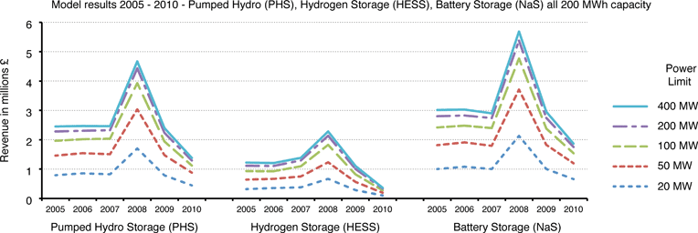 | ||
| Fig. 9 Graph showing the relationship between the charging/discharging power and revenue generated for the systems modelled in Table 2. | ||
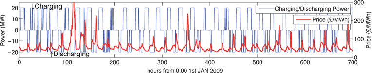 | ||
| Fig. 10 The optimal schedule of operation for the 200 MWh, 20 MW Pumped Hydro Storage system from Table 2 during the first 700 h of 2009, along with the corresponding UK spot market price. | ||
7 Discussion
The output schedules of the model in section 5 (of which Fig. 10 is typical) seem to favour arbitrage cycles of at least a diurnal nature in order to maximise the revenue from time-shifting. In essence, the model seems to favour a dispatch schedule that tends to mimic the period of the underlying price file, and if this happens to be diurnal in nature, the schedule will tend to be diurnal in nature too. This is an important consideration for policy makers to be aware of regarding the promotion of bulk energy storage – indeed – if the payment mechanism for stimulating investment in bulk storage is through the spot market – then storage operators will tend to follow the period of the underlying price structure, and this may or may not be a desirable timeframe for storage. Policy makers should also take account of the other markets from which energy storage devices can derive revenue streams, e.g. balancing and black start markets, as provision of one service may preclude or disrupt the provision of a similar service to a differing market.Table 2 shows that more revenue is generated with an increased power rating and as each data point in the spot price input file has a timeframe of 30 min, increasing the discharging/charging power beyond that which can entirely empty/fill the storage system in 30 min will not generate any additional revenue. With regard to the scenarios in Table 2, increasing the charging/discharging power beyond 400MW will generate no additional revenue.
As initially expected, the output in Fig. 10 shows that in order to maximise the revenue generated, the storage schedule buys at times of lower prices and sells at times of higher prices. The spot market price is influenced by a multitude of variables, but a major factor is the marginal cost of the next generating plant that offers to sell energy into the market. Therefore it is expected that a storage device operating on the spot market will act such as to smooth the variability between demand and supply and by doing so increase the overall reliability of the system. While this may be of a wider social benefit to the system, there is no mechanism by which the storage operator is paid for these benefits through the spot market. Furthermore, a situation is forseeable in which a large amount of wind energy becomes available at a time of low demand. A storage operator is likely to buy large amounts of this cheap electrical energy, and then sell it at times of higher demand and corresponding higher prices. This could reduce the need for higher marginal cost and carbon intensive peaking plant such as diesel or fuel oil generators.
The model results also clearly show that storage devices that have higher round trip efficiencies over the typical market time period will have greater upper boundary revenues than less efficient storage devices. In addition to this obvious conclusion, it is interesting to note that the variability of spot prices from year to year gives a greater risk to a storage operator in terms of upper boundary revenues than the efficiency of the device alone would suggest e.g. in the space of two years (from 2008–2010) the upper boundary of revenue dropped by approximately 75% – a high degree of revenue variability to account for in assessing the viability of a storage investment.
In terms of the amount of “storage” available to provide security of supply to any network – it is important to make a distinction between storage that works on a cycling timeframe of less than 48 h (less than hundreds of GWhours of storage), and storage that is at a strategic level (TWhours of storage) that may be hoped never to be used at all. The latter will have a cost – but the benefit could be argued to be a social benefit to the system as a whole and should therefore be funded through differing mechanisms than the revenues derived from the market based time-shifting of energy – indeed it could be considered as an insurance against the occasions when the network requires stores of energy that are large enough to last into the weeks–months range. These “stores” of energy are currently and historically in the form of coal, gas and nuclear fuel stocks, which may well continue to be used if low carbon abatement technologies allow. However, it would be perspicacious to consider the role for large-scale strategic storage that is not dependent on these fossil or nuclear fuelse.g.hydrogen or some other low carbon “fuel”.
If a long term goal is to be independent of fossil fuels – then the storage role currently carried out by fossil fuels will require replacement. It is likely that the size of future energy stores will be driven by future needs and markets, rather than the energy equivalents of historical fossil fuel stockpiles, which are driven by price variability and the perceived risks associated with long supply chains.
8 Conclusions
A model for determining the maximum possible revenue available to storage operators, operating on a market with a single valued price for a discrete time series has been presented. The model provides the optimal solution for the schedule of operation for a storage device that yields the upper boundary of revenue available from energy arbitrage. The model has the ability to simulate systems of various types, through the parameters of discharging and charging power limits, input efficiency, output efficiency, a self-discharge rate and maximum storage capacity. The input to the model is a time-series for the market index price in which the storage system operates.As demonstrated by the preliminary results, the model can be used to calculate the upper boundary of revenue on a per MW or a per MWh basis, for any given storage device. Thus far, the model has been used with historical electrical spot prices, whereas of course, any real world system would not be able to forecast prices perfectly. However, knowing the maximum revenue available to storage devices in previous markets should be a useful addition to the general knowledge base on storage. Therefore, a potential use of the model is to inform policy makers as to the type of incentives they may need to offer storage operators if they wish to encourage the inherent network reliability and potential carbon savings that come with bulk electrical energy storage devices.
Overall, the model is sufficiently robust and flexible enough to consider various types of storage devices in different markets.
A logical extension of the work carried out using the model would be to compare various storage technologies in different markets, in order to gain an idea of their comparative attractiveness as an investment. Also, if used in conjunction with the carbon intensity for differing generators, the overall CO2 production in electrical networks with and without storage could be estimated. If feasible, this could then be used to calculate any net CO2 savings resulting from the use of energy storage in an electricity network, e.g. when wind energy at a time of low demand is used to offset more CO2 intensive peaking plant at a later time. The algorithm has already been extended in order to compare the increased revenues available from using storage with renewable energy generation suffering from different levels of curtailment, although this is particularly network dependent. Further development of the model in this direction is a rich area of interest.
The method presented provides an objective tool with which to compare storage systems through the provision of a single value for the maximum achievable revenue for the time-shifting of electrical energy in historical markets. A storage operator would not have been able to derive a greater revenue than the upper boundary figure from arbitrage alone. For a full economic assessment, other costs would need to be included, e.g. the capital and operation/maintenance costs of the storage systems, as well as analysis of other potential sources of revenue such as the ancillary services markets.
The development and deployment of energy storage is essential as part of a sustainable and low carbon energy future. This itself is crucially dependent on a more detailed techno-economic analysis for both policy makers and potential investors alike, and the time-shifting model presented here provides valuable insights.
Appendix
The following appendix provides details of the Monte Carlo optimisation algorithm used to find the optimum schedule of operation of a storage device of specified characteristics. The algorithm runs an iterative search procedure of the space of feasible operations of the storage system. This space is defined by the characteristics of the storage system (efficiency, self-discharge, power limits, capacity) and by the physical constraint that the energy contained within the store cannot be negative. The inputs to the model are; a time-series for the price of electricity over the optimisation period (denoted price); values for the efficiency of transferring energy into and out of the store, ηin and ηout; a value for the maximum storage capacity, SOCmax; values for the storage charging and discharging limits, PLI and PLO; a value for the time constant of the store, τ (this can be directly converted into a self-discharge rate); and a value for the maximum number of iterations, nmax. The outputs are an array for the change in the state of charge (ΔSOC- the schedule of operation of the storage device), an array for Output “To the” or “Taken from” the Grid (OTG) and a single value for the total revenue yielded by the schedule of operation time-series ΔSOC, given by scalar product of the time-series price and OTG. The round trip efficiency of the store between two time periods t1 and t2 is given by eqn (1), where Δ t = t1 − t2.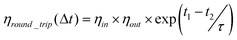 | (1) |
The following sequence describes the operation of the model:
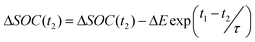
Firstly two time periods are selected in the price time series (the UK spot market period has a length of 30 min with a single associated price). The first is selected at random, and the second is selected with regard to a certain normal distribution around the first. This distribution is chosen depending on the capacity of the device and the time dependent loss rate of the store; if there is a very high loss rate (with time) then it is unlikely that storing energy between two periods that are separated by a long time will be optimal. Similarly, if the capacity of the store is small, then storing for a long time is unlikely to be optimal as it will render parts of store occupied for long periods. The earlier time period is assigned t1 and the later time period is assigned t2. The probability that a t2 will be selected given t1 is described by eqn (2). The parameter NNbias governs the width of the distribution.
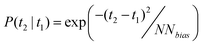 | (2) |
The model then increments a random change ΔE in the change in state of charge at t1 (eqn (1)) (between the maximum charging limit (which is positive) and maximum discharging limit (which is negative)). A positive ΔE corresponds to an increase in the energy stored at t1 (charging) and a negative amount of energy corresponds to a decrease in the energy stored at t1 (discharging).
The change in the state of charge at t2 is then altered by −ΔE × exp(Δt/τ).
The model then considers whether ΔE is positive or negative, and then whether the change in the state of charge (ΔSOC(t)) is positive or negative or 0 (i.e. net charge/net discharge/no action) at the particular time periods chosen.
There are then 8 possible scenarios that will determine the action of the model. These are formed by considering the action of the store at each of the periods in question. These scenarios are described below:
For ΔE > 0 (ΔE = 0 implies no action).
Scenario 1. ΔSOC(t1) ≥ 0 AND ΔSOC(t2) > 0.
Scenario 2. ΔSOC(t1) ≥ 0 AND ΔSOC(t2) ≤ 0.
Scenario 3. ΔSOC(t1) < 0 AND ΔSOC(t2) > 0.
Scenario 4. ΔSOC(t1) < 0 AND ΔSOC(t2) ≤ 0.
For ΔE < 0
Scenario 5. ΔSOC(t1) > 0 AND ΔSOC(t2) ≥ 0.
Scenario 6. ΔSOC(t1) > 0 AND ΔSOC(t2) < 0.
Scenario 7. ΔSOC(t1) ≤ 0 AND ΔSOC(t2) ≥ 0.
Scenario 8. ΔSOC(t1) ≤ 0 AND ΔSOC(t2) < 0.
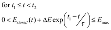
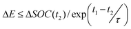
Any move of energy ΔE will only be accepted if, the stored energy doesn't exceed the maximum storage capacity or fall below zero in the range t1 ≤ t < t2, the energy into the store at t1 doesn't exceed the charging power limit of the storage system, and the energy out of the store at t2 doesn't exceed the discharging power limit. These constraints are shown in eqn (3), (4) and (5).
 | (3) |
| ELO ≤ ΔSOC(t1) + ΔE ≤ ELI | (4) |
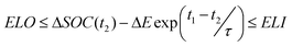 | (5) |
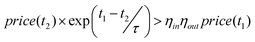
As initially there is no action of the store, the first move has to be made under scenario 2. This move will be accepted provided that there is a price increase of greater than 1/ηround_trip(Δt) between periods t1 and t2 (as shown in eqn (6)).
| price(t2) × ηround_trip(Δt) > price(t1) | (6) |
A move of ΔE is accepted under scenario 1 with the extra constraints shown in eqn (7) and (8), a move will be accepted under scenario 3 with the extra constraints shown in eqn (9) and (10), and a move will be accepted in scenario 4 if it also satisfies eqn (7) and (10).
 | (7) |
 | (8) |
 | (9) |
| ΔE ≤ −ΔSOC(t1) | (10) |
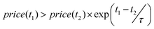
A move of ΔE is accepted under scenario 5 if it also satisfies (to re-iterate, all moves must satisfy eqn (5), (6) and (7)) eqn (11) and (12), under scenario 6 if it also satisfies eqn (12) and (13), under scenario 7 if it also satisfies eqn (14) and under scenario 8 if it also satisfies eqn (11) and (15).
 | (11) |
| ΔE ≥ −ΔSOC(t1) | (12) |
| price(t1) > ηround_trip(Δt) × price(t2) | (13) |
 | (14) |
 | (15) |
Scenarios 2 and 7 represent forward moves, while 1, 3, 4, 5, 6 and 8 can essentially be regarded as corrections for a sub-optimal moves (for example, a move under scenario 1 describes the situation in which charging at t1 gives more revenue than charging at t2, but this scenario can only arise after a move in scenario 2 – see Fig. 11 for a simple example).
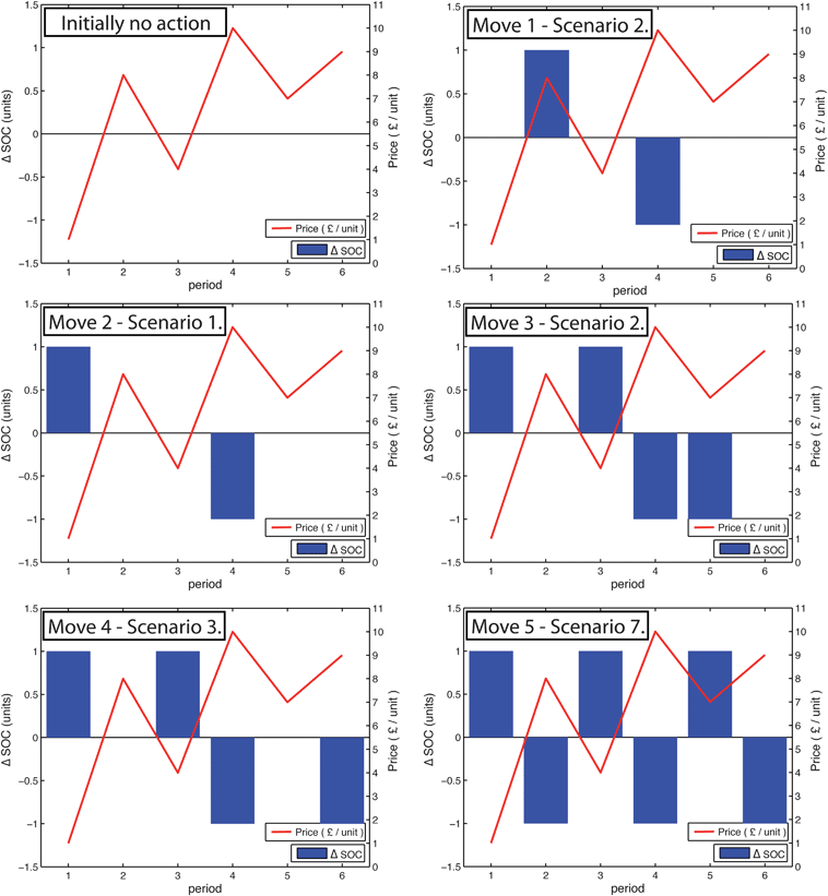 | ||
| Fig. 11 an illustrative of how the algorithm works. The figure depicts a possible path to the optimum solution for the algorithm on a 6 period time-series, for a storage device with capacity 3 units, power limits in and out (PLI and PLO) of 1 unit/period, and round trip efficiency of 100% over any time (τ = ∞ and ηin = ηout = 100%). | ||
If a move satisfies all the relevant constraints, then the model accepts the move and updates the charging/discharging schedule accordingly (eqn (16) and (17)):
| ΔSOC(t1) = ΔSOC(t1) + ΔE | (16) |
 | (17) |
In the case of an isolated storage system, the Output “To the” or “Taken from” the Grid (OTG(t)) is given by eqn (18) and (19):
| IF ΔSOC(t) ≥ 0 OTG(t) = −ΔSOC(t)/ηin | (18) |
| IF ΔSOC(t) < 0 OTG(t) = −ΔSOC(t) × ηout | (19) |
Then the revenue generated at each period, t, is (eqn (20)):
| R(t) = OTG(t) × price(t) | (20) |
The total revenue achieved over the time period in question is just the sum of the array R(t), 
Each iteration of the model repeats these steps. Once the solution reaches the point that the revenue doesn't increase with the number of iterations, the solution is considered to be optimal. In this case the model is unable to find any other movements of any amount of ΔE that will increase revenue, so further iterations cannot improve the solution. Every time the model increments a change ΔE in the change of state of charge (whether it is accepted or not) counts as an iteration and the counter, n, is incremented by 1. The optimisation procedure is ended once n = nmax.
Fig. 11 shows an illustrative example of how the model finds the optimum solution for a short time-series. The capacity is set at 3 units, the charging and discharging power limits in to and out of the store are 1 unit per period and to simplify matters there are no losses, i.e. τ = ∞, and, ηin = ηout = 100%. At the start there is no action of the storage system so the schedule of operation is initially flat (=0 at every period). The figure shows a possible path the algorithm could take to the optimum result, with the bars representing ΔSOC and the red line representing the price. It should be noted that the even though the price is described by a continuous line (as is the convention), it is really a stepped function where the price at the start of the integer time period describes the price until the beginning of the next integer time period.
The first move charges at period 2 and discharges at period 4, which reduces the revenue at 2 by £8 and increases the revenue at 4 by £10, therefore increasing the total by £2.
The second move charges at period 1 instead of at 2, as charging at 1 costs £1, rather than £8 at 2. The overall revenue is therefore increased by £7.
The third move charges at period 3 and discharges at period 5. It increases the total revenue by £3.
The fourth move increases the total revenue by £2, as discharging at period 6 generates more revenue than discharging at 5.
The last move (move 5) realises that there is energy stored at period 2, which could be discharged and recharged at a lower price at period 5. This move is only allowed as the energy discharged at period 2 is not required until after the store has been re-charged at period 5.
The schedule after move 5 is the optimum schedule of operation of the storage device with PLI = PLO = 1unit/period over the price time-series given. There are no more moves of ΔE which can increase the revenue, and only that schedule of operation will generate a total revenue of £15. This is one of many paths to the optimum solution.
| η in | fixed input transfer efficiency of the storage system |
| η out | fixed output transfer efficiency of the storage system |
| η round_trip (Δt) | round trip efficiency, including time dependent efficiency |
| τ | storage time constant |
| ΔE | an amount of energy to be moved |
| n | the counter for the iterations |
| n max | the maximum number of iterations |
| NN bias | Nearest Neighbour bias when choosing two time periods |
| PLI | Power Limit Into the store |
| PLO | Power Limit Out of the store |
| price(t) | spot market price at time t |
| R(t) | Revenue generated at time t from the sale of energy |
| SOC max | the maximum capacity of the store |
| ΔSOC(t) | change in the state of charge at time t |
| SOC(t) | the state of charge of the store at time t |
| t | time period |
Acknowledgements
The authors would like to thank the following people: Dr Leo Lue of the University of Strathclyde and Bruce Duncan and Richard Ferrier of the University of Edinburgh for invaluable help with the programming methods. This work was supported by the ESPRC under grants EP/H019596/1, EP/G031681/1 and EP/E040136/1 & ESPRC DTG Grant number J74909.References
- N. Lannen, 2010. Scottish and Southern Energy presentation. http://kn.theiet.org/communities/powersys/resources/presentations/pumped-storage-proposals.cfm?type = pdf [Accessed 4/8/11].
- DUKES 2010, Digest of United Kingdom energy statistics 2010. Electricity generated and supplied, 1970 to 2009 (DUKES 5.1.3) URL http://www.decc.gov.uk/ Search PubMed.
- J. Cox, 2010. Implications of intermittency. Pöyry, Oxford, UK. http://www.ilexenergy.com/pages/Documents/Other/Poyryarticle_New%20Power%208.pdf [Accessed 4/8/11] Search PubMed.
- R. Gross, et al., Renewables and the Grid: Understanding Intermittency, Proceedings of the ICE - Energy, 2007, 160(1), 31–41, DOI:10.1680/ener.2007.160.1.31.
- R. Green and N. Vasilakos, Market behaviour with large amounts of intermittent generation, Energy Policy, 2010, 38, 3211–3220 CrossRef.
- AEP, 2011. Association of Electricity Producers website. URL, http://www.aepuk.com/about-electricity/electricity-market/. [Accessed 4/8/11].
- I. A. G. Wilson, P. McGregor, D. G. Infield and P. Hall, Grid-connected renewables, storage and the UK electricity market, Renewable Energy, 2011, 36(8), 2166–2170, DOI:10.1016/j.renene.2011.01.007.
- I. A. G. Wilson, P. McGregor and P. Hall, Energy storage in the UK electrical network: Estimation of the scale and review of technology options, Energy Policy, 2010, 38(8), 4099–4106, DOI:10.1016/j.enpol.2010.03.036.
- R. Weron, 2005. Heavy tails and electricity prices. Wroclaw University of Technology, Research Report, HSC/05/2, 2005. http://www.im.pwr.wroc.pl/∼hugo/publ/HSC_05_2_RWeron_Bundesbank.pdf [Accessed 4/8/11] Search PubMed.
- M. Madalena, J. C. Pinho, C. Ribéiro 2008. Some stylized facts in electricity markets: a European comparison. www6.fe.uc.pt/pfn2008/UserFiles/pdf/724.pdf [Accessed 4/8/11].
- R. Weron, Modeling and Forecasting Electricity Loads and Prices: A Statistical Approach,John Wiley and Sons, Chichester, 2006. ISBN-13: 978-0470057537 Search PubMed.
- P. Mokrian and M. Stephen, 2006. A Stochastic Programming Framework for the Valuation of Electricity Storage URL http://www.iaee.org/en/students/best_papers/PedramMokrian.pdf [Accessed 4/8/11].
- C. Crampes and M. Moreaux, Pumped storage and cost saving, Energy Econ., 2010, 32(2), 325–333, DOI:10.1016/j.eneco.2009.10.004.
- F. C. Figueiredo and P. C. Flynn, Using diurnal power price to configure pumped storage, IEEE Trans. Energy Convers., 2006, 21(3), 804–809, DOI:10.1109/TEC.2006.877373.
- E. Barbour and I. G. Bryden, Energy storage in association with tidal current generation systems, Journal of Power and Energy, 2011 DOI:10.1177/0957650911399014.
- D. Connolly, H. Lund, P. Finn, B. V. Mathiesen and M. Leahy, Practical operation strategies for pumped hydroelectric energy storage (PHES) utilising electricity price arbitrage, Energy Policy, 2011, 39(7), 4189–4196 CrossRef.
- Elexon. Market Index Data (Spot Price) - ELEXON Portal website. URL, https://www.bsccentralservices.com/, 2011, [Accessed 4/8/11].
- S. B. Darling, F. You, T. Veselka and A. Velosa, Energy Environ. Sci., 2011, 4, 3133–3139 Search PubMed.
- S. M. Schoenung, et al., Energy storage for a competitive power market, Annu. Rev. Energy Environ., 1996, 21, 347–370, DOI:10.1146/annurev.energy.21.1.347.
- H. Ibrahim, A. Ilinca and J. Perron, Energy storage systems—Characteristics and Comparisons, Renewable Sustainable Energy Rev., 2008, 12(5), 1221–1250, DOI:10.1016/j.rser.2007.01.023.
- B. Tamurek, D. K. Nichols and O. Demirci, The NAS Battery: A Multi-Function Energy Storage System. Power Engineering Society General Meeting, IEEE, 2003, 4, 13–17, DOI:10.1109/PES.2003.1270917.
| This journal is © The Royal Society of Chemistry 2012 |