DOI:
10.1039/C1EE02539B
(Communication)
Energy Environ. Sci., 2012,
5, 5257-5264
Novel CO2-tolerant ion-transporting ceramic membranes with an external short circuit for oxygen separation at intermediate temperatures
Received
1st September 2011
, Accepted 16th November 2011
First published on 1st December 2011
Abstract
Here we report a new concept for oxygen separation by the oxygen ion conducting ceramic membrane with an external short circuit. With the strong chemical stability against acidic gases like CO2 and the higher oxygen fluxes at lower temperatures, this novel membrane concept could possibly result in a breakthrough for tonnage oxygen production to improve the viability of these clean energy technologies.
Broader context
Global climate change is challenging the existing power generation system and new clean energy delivery technologies with reduced CO2 emissions are urgently required. In order to produce clean electricity without dismantling the existing coal-fired power station, oxyfuel combustion technology is attracting billion dollar investment for a few demonstration projects. To make these low emission technologies commercially acceptable, the investment and operation costs need to be reduced, particularly from the most expensive unit-air separation via the cryogenic method. In this context, oxygen ion-conducting ceramic membranes have received increasing attention because they are envisaged to replace the cryogenics and can significantly reduce O2 production cost offering the potential to tackle these energy penalties and improve the viability of zero emission technology. However, all the existing membranes suffer from either the low oxygen permeation fluxes or the low structural stability to withstand the real process conditions. This work presents a new membrane concept of using these CO2 tolerant ion-conducting ceramic membranes with an external short circuit for oxygen separation at relatively low temperatures, which possibly brings in a breakthrough for tonnage oxygen production to improve the viability of these clean energy technologies.
|
Global climate change is challenging the existing power generation system and new clean energy delivery technologies with reduced CO2 emissions are urgently required. Among the promising options to integrate the existing coal-fired power stations with CO2 capture to produce low emission electricity, oxyfuel combustion seems to be more feasible than other options and several big projects have been initiated in the world such as CS Callide (Australia), Vattenfal (Germany), Inabensa (Spain), OXY-CFB-300 (Spain), TotalLacq (France) and FutureGen2 (USA) program with billion dollar investments for each of these projects. Under the oxyfuel concept, coal will be fired with pure O2 or an O2/CO2 mixture instead of air; the major constituent of the waste gas produced during the new combustion process is highly concentrated CO2 enabling its capture more economically feasible.1–5 However, all these oxyfuel combustion projects are still in the demonstration stage and cannot compete commercially with the conventional air-fired coal power plants because of the significantly high investment and operation costs. Among the basic operational units of the oxyfuel combustion, the complex air separation unit (ASU) via the cryogenic method to provide pure oxygen is the most expensive section, accounting for approximately 50% of the overall CO2 capture cost.6,7 Addressing this concern to reduce the cost, oxygen ionic conducting ceramic membranes have received increasing attention because they are envisaged to replace the cryogenics and reduce O2 production cost by 35% or more, offering the potential to tackle these energy penalties and improve the viability of zero emission technology.8–12 However, these membranes must possess sufficiently high oxygen permeability and structural stability to withstand the real process conditions which include the presence of highly concentrated CO2.
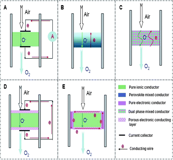
The two main categories of ionic transport ceramic membranes for oxygen separation attracting intense attention are pure oxygen ion conducting membranes13,14 and mixed ionic–electronic conducting (MIEC) membranes.15–21 For the pure ion conducting membranes with the concept schematically shown in Fig. 1A, an external power source and electrodes are required to provide the electric current. Driven by the electrical potential gradient, the oxygen transport can be precisely controlled in quantity by applying the electric current so the oxygen can be pumped in either direction regardless of the oxygen partial pressure gradient. Because of the structural complexity with external electric loadings, pure oxygen ion conducting membranes are seldom used for gas separation, in contrast to their broad application in the fields of solid oxide fuel cells (SOFCs).22–24 The MIEC membranes, driven by oxygen pressure gradients without the requirement of electrodes and external power source to operate, can consist of one single phase capable of both ionic and electronic conduction (Fig. 1B) or dual phases i.e. with one metal (or perovskite) phase for electronic conduction and the other phase from fluorite structures for ionic conduction (Fig. 1C). In MIEC membranes, as oxygen is transported in the ionic form only from the high concentration side to the low concentration side, there must be a simultaneous flux of electrons in the opposite direction to charge compensate the oxygen flux to ensure the overall electric neutrality criteria. Currently, the intense studies of these single phase MIEC membranes have focused on perovskite oxides with a general formula of AyA′(1−y)BxB′(1−x)O(3−α)(x, y = 0–1) where the A and A′ elements belong to the group consisting of La, Sr, Ba, Ca or Zr; the B and B′ elements are taken from the group consisting of Mg, Al, Ti, Cr, Mn, Fe, Co, Ni, Cu, Ga, Zr, or Zn.25–31 These perovskite membranes are characterized by super-high oxygen fluxes, but they suffer from poor chemical stability in real application conditions in the presence of gases like CO2, H2S, H2O, CH4etc. This is due to the reactions between the oxides and the gases which can destroy the perovskite structure and induce new phase formations and gradually lead to membrane failure. By contrast, the dual phase membrane is a promising alternative, as these fluorite oxides possess inherently high chemical stability against these acidic or reducing gases. Previously, the dual phase membranes were prepared by combining one of the metal phases usually chosen from Ag, Pd, Au, or Pt and the other from the ion conducting phases with examples like yttria-stabilized zirconia (YSZ), Sm-doped ceria (SDC) or Gd-doped ceria (GDC).32–34 Each of the conducting properties requires a continuous material pathway which poses challenges on the preparation protocol regarding the mixture portions, mixing method, the particle size of the chosen membrane materials and the high material costs. These high material costs cannot be avoided due to the large amount of precious metals used to form a continuous electronic conducting phase. The mismatch of these factors usually leads to the very low oxygen permeation fluxes, sometimes several orders of magnitude lower than the single phase perovskite membranes. Reviewing all the results of the currently developed ionic transport ceramic membranes for O2 separation, we note that a good ceramic membrane addressing all the application criteria is rarely encountered. There is always a balance between the chemical stability and oxygen flux with improvements in one property to the detriment of the other property.
In order to solve this dilemma, in this report, based on the progress of solid oxide fuel cells and mixed conducting membranes, we devised a new kind of ion conducting ceramic membrane with an external short circuit for oxygen separation. As shown in Fig. 1D, similar to the traditional dual phase membrane, the new concept membrane consists of a fluorite phase and a metal phase. However, the novelty here is that the porous metal phase is being coated on the surface of the dense or gas tight fluorite phase membrane, but not being mixed inside the bulk fluorite with large amounts of precious metal as in previous methods. It should be mentioned that precious metal coating is one of the strategies often applied to the single phase MIEC membranes to improve the oxygen fluxes by enhancing surface reaction kinetics.35 In order to provide the continuous metal phase for electron conduction, the two sides of the coated metal layers, which also can be called cathode and anode adapted from the configurations of solid oxide fuel cells, are connected by one or two external wires. In this way, the mixed conducting function can be realised via the oxygen ion diffusion inside the fluorite bulk and electronic conduction along the external metal wires avoiding the mutual obstruction often resulting from the powder mixing of the two phases. Coincidently, silver paste is usually used to seal the ceramic membranes between the two different gas chambers. In this case, the external wire is no longer required and the electronic conduction can be realised via the silver sealing as long as the silver sealing touches the coated porous metal layer. This results in a very simplified membrane configuration as displayed in Fig. 1E. In this report, this new membrane concept for oxygen separation has been experimentally verified by measuring the oxygen permeation flux and the electrical current. Hopefully, this work will open a new research area in the field because the high chemical stability of these fluorite-based ceramics can resist the harsh practical conditions and the high oxygen fluxes of the membranes at relatively lower temperatures.
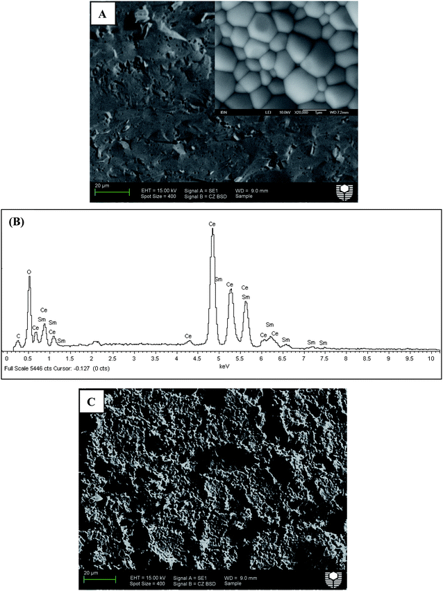
Sm-doped ceria (SDC) and yttria-stabilized zirconia (YSZ) are commonly used as oxygen ion conducting solid electrolytes in solid oxide fuel cell (SOFC) systems with the former able to be applied in the intermediate temperature range because of its higher ionic conductivity compared to YSZ at this temperature range.36 Here, SDC, Ag or Pt coating, Ag wire, Ag paste and normal non-conductive ceramic paste have been used to demonstrate this concept step by step. SDC was synthesized by a combined EDTA–citrate complexing sol–gel process where Ce(NO3)2·xH2O and Sm(NO3)3·xH2O were applied as the metal-ion sources. To compare the phase stability properties of SDC and perovskite membranes, a typical perovskite with the composition Ba0.5Sr0.5Co0.8Fe0.2O3−δ (BSCF) powder was also prepared by this method. Fig. 2 shows the typical XRD pattern. The characteristic peak locations at the respective 2θ angles of 28° (111), 33° (200), 47° (220), 52° (311), 58° (222) and 76° (331) are closely matching the reported fluorite structure.37 To synthesize the SDC membrane, the as-obtained oxide powder was hydraulically pressed into disk-shape membranes and subsequently sintered at 1500 °C to achieve the required densification with good mechanical strength and gas-tightness. The sintered SDC membranes have a diameter of 12 mm and the thickness ranged from 0.4 to 1.0 mm. Fig. 3A shows the dense structure after sintering, with well-defined grains having grain sizes in the order of 0.5 to 1 μm. Energy-dispersive X-ray spectra (EDXs) in Fig. 3B verified the presence of cerium, samarium and oxygen. The chemical composition analysis from EDXs indicates that the ratio of Sm and Ce is 0.27![[thin space (1/6-em)]](https://www.rsc.org/images/entities/char_2009.gif) :0.80, approximately equal to the ratio initially designed for Sm0.2Ce0.8O1.9. Actually, the precise SDC stoichiometry was controlled by the careful addition of Sm(NO3)3 and Ce(NO3)2 with a strict molar ratio at 1:4 in the starting solution for the SDC powder synthesis. The SDC membranes were tested at room temperature for gas-tightness. Porous platinum or silver layers with a thickness of 5–10 μm were coated on both sides of the SDC membrane by brushing on the platinum or silver paste. Fig. 3C depicts the surface morphology change after Pt deposition. Different SDC membranes shown in Fig. 1 were tested for the oxygen permeation under the sweep gas mode. Table 1 shows the seven typical SDC membranes being tested with Samples I–V to verify the concept, Samples V–VII to show the effects of thickness on membrane performance and Samples VII and VIII to compare the stability. The O2 permeation flux values of these different membranes are comparatively displayed in,Fig. 4–8 which will be explained and discussed in more detail subsequently. Sealed by normal nonconductive ceramic paste, Sample-I was a plain SDC disk without any Pt/Ag coating. As expected, the pure ion conducting SDC membrane without the second metal phase or Pt/Ag coating layer for electronic conduction does not possess any O2 permeation in the investigated temperature range from 500 to 800 °C due to the lack of electronic conducting property. Actually, this is the reason for SDC to be widely applied as an excellent pure ion-conductor in the area of SOFCs. Sample-II is the conventional dual phase membrane made by sintering the mixture of Ag and SDC powders. As can be seen, when the operating temperature was increased from 500 to 700 °C, almost no oxygen permeation flux could be detected; only after 700 °C, the oxygen flux values up to 0.03 mL·cm−2·min−1 were observed at 800 °C. In Sample-III with working principles shown in Fig. 1D, both sides of the pure SDC membrane were coated with porous Ag layers and connected by an Ag wire, but the coated SDC membrane was sealed to the quartz tube with ceramic paste. The O2 permeation through Sample-III was clearly observed with flux values presented in Fig. 4. The flux at 600 °C was 0.027 mL cm−2 min−1, but improved to 0.52 mL cm−2 min−1at the higher temperature of 800 °C in sharp contrast with a lower flux value of 0.03 mL cm−2 min−1 from Sample-II and zero flux of Sample-I at a similar temperature. This is the direct experimental evidence for the oxygen permeation through this new membrane concept via the SDC phase for ionic diffusion and the external Ag coating plus Ag wire for electronic conduction together with the two surface reactions:
:0.80, approximately equal to the ratio initially designed for Sm0.2Ce0.8O1.9. Actually, the precise SDC stoichiometry was controlled by the careful addition of Sm(NO3)3 and Ce(NO3)2 with a strict molar ratio at 1:4 in the starting solution for the SDC powder synthesis. The SDC membranes were tested at room temperature for gas-tightness. Porous platinum or silver layers with a thickness of 5–10 μm were coated on both sides of the SDC membrane by brushing on the platinum or silver paste. Fig. 3C depicts the surface morphology change after Pt deposition. Different SDC membranes shown in Fig. 1 were tested for the oxygen permeation under the sweep gas mode. Table 1 shows the seven typical SDC membranes being tested with Samples I–V to verify the concept, Samples V–VII to show the effects of thickness on membrane performance and Samples VII and VIII to compare the stability. The O2 permeation flux values of these different membranes are comparatively displayed in,Fig. 4–8 which will be explained and discussed in more detail subsequently. Sealed by normal nonconductive ceramic paste, Sample-I was a plain SDC disk without any Pt/Ag coating. As expected, the pure ion conducting SDC membrane without the second metal phase or Pt/Ag coating layer for electronic conduction does not possess any O2 permeation in the investigated temperature range from 500 to 800 °C due to the lack of electronic conducting property. Actually, this is the reason for SDC to be widely applied as an excellent pure ion-conductor in the area of SOFCs. Sample-II is the conventional dual phase membrane made by sintering the mixture of Ag and SDC powders. As can be seen, when the operating temperature was increased from 500 to 700 °C, almost no oxygen permeation flux could be detected; only after 700 °C, the oxygen flux values up to 0.03 mL·cm−2·min−1 were observed at 800 °C. In Sample-III with working principles shown in Fig. 1D, both sides of the pure SDC membrane were coated with porous Ag layers and connected by an Ag wire, but the coated SDC membrane was sealed to the quartz tube with ceramic paste. The O2 permeation through Sample-III was clearly observed with flux values presented in Fig. 4. The flux at 600 °C was 0.027 mL cm−2 min−1, but improved to 0.52 mL cm−2 min−1at the higher temperature of 800 °C in sharp contrast with a lower flux value of 0.03 mL cm−2 min−1 from Sample-II and zero flux of Sample-I at a similar temperature. This is the direct experimental evidence for the oxygen permeation through this new membrane concept via the SDC phase for ionic diffusion and the external Ag coating plus Ag wire for electronic conduction together with the two surface reactions:
| ½O2 + 2e + V˙˙o → Oxo (O2 high pressure side); |
| Oxo + 2h˙ → ½O2 + V˙˙o (O2 low pressure side). |
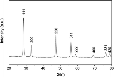 |
| | Fig. 2 XRD pattern of the SDC powder prepared by the EDTA–citrate method after heat treatment at 700 °C in air for 5 hours. | |
Table 1 SDC membrane structure, coating material, sealing agent and membrane thickness
| Sample no. |
Structure typea in Fig. 1 |
Coating material |
Sealing agent |
Membrane thickness |
|
The working principles are schematically shown in Fig. 1.
The ceramic paste is not electronic-conductive.
|
| I |
Pure SDC |
Without coating |
Ceramic pasteb |
1 mm |
| II |
C (dual phase) |
Without coating |
Ceramic paste |
1 mm |
| III (with Ag wire) |
D |
Ag |
Ceramic paste |
1 mm |
| IV |
E |
Ag |
Ag paste |
1 mm |
| V |
E |
Pt |
Ag paste |
1 mm |
| VI |
E |
Pt |
Ag paste |
1.5 mm |
| VII |
E |
Pt |
Ag paste |
0.4 mm |
| VIII |
B (perovskite) |
Without coating |
Ag paste |
1 mm |
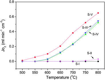 |
| | Fig. 4 Oxygen permeation fluxes (±5%) through various SDC membranes with 1 mm-thickness at different temperatures. S-I: Pure SDC without any coating; S-II: SDC (65 wt%) + Ag (35 wt%) dual phase membrane prepared by powder mixing and sintering at 950 °C; S-III: SDC + Ag coating + Ag wire; S-IV: SDC + Ag coating + Ag sealing; S-V: SDC + Pt coating + Ag sealing. | |
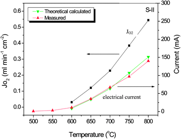 |
| | Fig. 5 Effects of operating temperature on oxygen fluxes (±5%) through Sample-III SDC membrane (SDC + Ag coating + Ag wire) and the electrical current through the external wire with values measured and theoretically calculated. | |
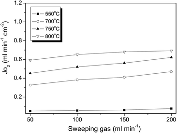 |
| | Fig. 6 Effects of helium sweep rate on the oxygen fluxes (±5%) through the SDC membrane of Sample-V with 1 mm thickness (SDC + Pt coating + Ag sealing). | |
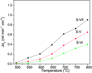 |
| | Fig. 7 Thickness dependence of oxygen permeation fluxes (±5%) through the SDC membrane (samples (V to VII) with different thickness (S-V: 1 mm, S-VI: 1.5 mm, S-VII: 0.4 mm). | |
 |
| | Fig. 8 The long term oxygen permeation fluxes (±5%) through Sample-VII (SDC) membrane (0.4 mm) at 600 °C (A) and Sample-VIII (BSCF) membrane (1 mm-thickness) at 850 °C (B) under He or He + CO2 mixture (total sweep gas flow: 100 mL min−1). | |
The electrical current through the Ag wire in Sample-III was measured by a multimeter with values shown in Fig. 5 together with the measured oxygen fluxes at the same operating conditions. As can be seen, the electrical current was very low at lower temperatures, but it increased sharply with the temperature increases, which was due to the facilitated oxygen reduction and oxidation processes at the membrane surface by the higher temperature activation. In other words, more electrons were produced and consumed during these more active processes, which produces a higher electrical current. For instance, the electrical current value of 11 mA at 600 °C was improved to 140 mA at 800 °C. In theory, the electrical current value through the external wire should be equivalent to the current by ionic conduction through the SDC bulk membrane for a pure ionic conductor. In this case, the relationship between the oxygen flux and the measured current can be described by the equation as below:38
| I (current: A) = 4F (Faraday constant) × JO2 (oxygen flux: mol s−1). |
From this correlation, we can use the measured oxygen permeation fluxes to calculate the electrical currents or vice versa. Further inspection of Fig. 5 indicates that the measured electrical current values are matching very well with the calculated values from the measured oxygen fluxes, particularly in the lower temperature range. However, in the higher temperature range from 700 to 800 °C, the calculated current values are slightly higher than the measured values. This can be explained by the reason that at high temperatures, for example above 700 °C, the SDC is not a pure ionic conductor but displays a certain mixed conduction together with electronic conduction. Therefore the difference between the calculated electrical current values and the measured one is due to the direct electrical conduction through the SDC bulk.
S-IV displayed the concept (Fig. 1E) of using an Ag seal to replace the Ag wire for oxygen permeation with electronic conduction through the continuous Ag phase from coating and sealing. As can be seen from Fig. 4, the flux value of S-IV is almost similar to that of S-III indicating the feasibility of simplifying the membrane configuration by avoiding the attachment of an electrode and wire connection. Under this concept, S-V (Fig. 4) depicts the permeation results of Pt coating rather than Ag. Actually, the coated precious metal layer on the membrane surface would not only work as an electronic conducting phase but also as the catalyst to speed up the surface reactions. It is well known that Pt is a better catalyst than Ag for oxygen to be reduced to lattice oxygen when SDC is used as the electrolyte for oxygen ion conduction in SOFCs.39,40 In agreement with this, oxygen fluxes of S-V (in Fig. 4) could be observed with appreciable values at much lower temperatures than that from S-IV due to the better catalytic efficiency of Pt. Fig. 4 also shows that the O2 fluxes through the ceramic membranes with external short circuits increased significantly with operating temperature. This phenomenon was normally observed for many other mixed conducting membranes, which can be explained by the improvements in ionic transport rates in the membrane bulk and two surface exchange reaction rates with the temperature increase. For instance, O2 flux through S-V at 550 °C has been increased by a factor of 11 at 800 °C.
Fig. 6 shows that the oxygen flux was enhanced with the rise of the helium sweep rate. At 700 °C, for example, boosting the helium flow rate from 50 to 200 mL cm−2 lowered the oxygen partial pressure from 0.0067 to 0.0024 atm in the permeate side; as a result, the oxygen flux was improved from 0.32 to 0.47 mL cm−2 min−1. The effect of the sweep flow rate on the oxygen flux has been noted on other membranes.41 The flux improvement is obviously due to the increase of the driving force by lowering the oxygen partial pressure at the permeate side. Fig. 7 illustrates the effects of SDC membrane thickness on the permeation fluxes. As can be seen, a decrease in SDC thickness resulted in higher oxygen fluxes. For instance, reduction of the membrane thickness by a factor of 3.7 from 1.5 to 0.4 mm increased the oxygen fluxes by approximately the same factor of 3.0 from 0.21 to 0.61 mL cm−2 min−1 at 700 °C. The inverse linear relationship between the oxygen fluxes and the membrane thickness indicates the ionic diffusion in the SDC bulk is the controlling step consistent with the Wagner theory. With this finding, the higher oxygen fluxes can be easily achieved by reducing the SDC thickness via coating or hollow fibre technology. Compared to dual phase membranes via the conventional concept by mixing two phases together, the novel SDC membranes exhibited fluxes at least two orders of magnitude higher than that from YSZ based membranes at a similar membrane thickness and operating conditions.34 More striking is that the novel membrane can deliver appreciably higher fluxes at relatively lower temperatures starting at 500 °C which compares very differently with the developed single phase perovskite disk-shaped membranes which usually require higher temperatures than 800 °C. It should be mentioned that the oxygen permeation fluxes can be significantly improved by applying thin membrane technology, i.e., in hollow fibre geometry. Oxygen permeation fluxes with appreciable values through these perovskite hollow fibers can be achieved from 0.25 to 0.45 mL cm−2 min−1 even at a lower temperature of 500 °C.42,43 In this regard, we are in the process of preparing SDC hollow fibre membranes and therefore more information regarding the relationship between membrane structure and performance will be provided in future work.
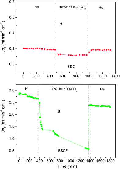
Fig. 8 shows the oxygen flux stability of the new SDC membrane (Sample-VII) and makes a comparison with the typical perovskite BSCF membrane under the gas mixture with 10% CO2 plus 90% He. The coated SDC membranes with 0.4 mm-thickness display very stable oxygen fluxes in not only He but also in CO2 containing mixtures. After switching the sweep gas from pure He to the CO2 containing mixture gas, the fluxes decreased to lower but stable values; and when the sweep gas was changed back to He, the oxygen flux was fully recovered to the original values. The lower flux value in the mixture gas is due to the stronger CO2 adsorption to the membrane surface, but not due to the reaction between CO2 and SDC. It is well known that SDC can withstand the presence of CO2. However, in the case of perovskite BSCF membrane (Sample-VIII), just as evidenced from Fig. 8B, the oxygen permeation flux experienced a continuing decline even with pure He as the sweep gas. Perovskite BSCF is very sensitive to CO2 and H2O even with low concentrations in air atmosphere. Furthermore, after the sweep gas was switched to the 10% CO2 containing gas, the oxygen flux dropped very sharply, bottoming out at only 0.57 mL cm−2 min−1 at ∼1400 min with 80% loss of the initial oxygen flux at 2.87 mL cm−2 min−1. Even when operated for more than 1000 minutes, the flux still kept decreasing. When the sweep gas was changed back to pure helium, the oxygen permeation flux of perovskite BSCF could not be recovered to its original value due to the carbonate formation from the reactions between the alkaline earth metals like Ba/Sr and CO2 at high temperatures.44,45 Although the stability of these two membranes was tested for less than 30 hours, this striking comparison strongly proves that this new concept membrane has an excellent tolerance for CO2 gas. For the practical application in oxyfuel combustion, the membrane will be exposed to the gas atmosphere containing corrosive acid gases like CO2 and H2S. Sufficient chemical stability of the membrane materials against these acidic gases will be the first prerequisite to be considered for further applications. In this sense, the mechanically robust SDC ceramic is satisfying this condition as its good chemical stability has already been confirmed from other studies using SDC as the solid electrolyte for solid oxide fuel cells.46,47
Conclusions
Conventional dual phase membranes made by mixing two phases together to form two distinct and continuous material networks for electronic and ionic conduction are usually characterised by very low O2 permeation fluxes and high material cost. Single phase mixed conducting perovskite membranes suffer from poor chemical stability under the real application conditions. Combining the recent progress in solid oxide fuel cells and mixed conducting membranes, a new ion conducting ceramic membrane concept with an external short circuit has been put forward and experimentally verified step by step based on an SDC disk, Pt/Ag coating, Ag wire and Ag sealing with the measurement of oxygen permeation flux and electrical current. Higher O2 permeation fluxes through the new concept membranes have been observed at relatively lower temperatures. A strong correlation between the membrane thickness and the O2 flux values implies the membrane performance can be further improved by reducing the membrane thickness. Considering the high O2 fluxes, the intermediate operating temperature and the well-known high stability of the fluorite membrane structure, this work is possibly making a breakthrough in the field of oxygen production for clean energy delivery.
Experimental
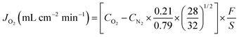
Sm0.2Ce0.8O1.9 (SDC) composite oxides were synthesized by a combined EDTA–citrate complexing sol–gel process. Ce(NO3)2·xH2O and Sm(NO3)3·xH2O (A.R. grade) were applied as the raw materials for the metal-ion sources. For the precise control of the doping concentration, the individual metal nitrates were dissolved in aqueous solutions to determine their precise compositions by the standard EDTA titration technique. For the fabrication of ceramic membranes, the as-obtained oxide powders were pressed into disk-shape membranes in a stainless steel module (15.0 mm in diameter) under a hydraulic pressure of approximately 1.5 × 10⁸ Pa. These green membranes were further sintered in an electrical furnace at 1500 °C in air for 5 h at a heating/cooling rate of 1–2 °C min−1. The thickness and diameter of the sintered electrolyte disks were ∼0.4 to 1.5 and ∼12 mm, respectively. The dual phase Ag/SDC membrane was synthesized by mixing 35 wt% Ag and 65 wt% SDC powder, and then sintering at 950 °C for 5 h. Ba0.5Sr0.5Co0.8Fe0.2O3−δ (BSCF) perovskite membranes for oxygen permeation comparison purpose were also prepared by the above mentioned EDTA–citrate method. The green BSCF membranes were then sintered at 1000 °C in air for 5 h with the similar condition as that for the SDC membrane. Silver or platinum slurry was applied to each side of the SDC membrane substrate as symmetrically as possible by the paint-brushing method and then calcined at 600 °C in air for 2 h. A silver wire was used as the conductive wire to connect the two sides of membranes. Scanning Electron Microscopy (SEM) images were obtained using a Zeiss EVO 40XVP at an accelerating voltage of 15 kV. The XRD analysis was carried out on a Bruker D8 Advance X-ray diffractometer using Cu Ka radiation generated at 40 kV and 30 mA. The electrical current was measured with a HY H-15 Volt–Ohm–Milliammeter. Permeation properties of the membranes were investigated by the gas chromatography (GC) method. A silver paste or non-conductive ceramic paste was used as the sealant to fix the membrane disk onto a dense quartz tube and an effective area of 0.45 cm2 was exposed at the sweep side for permeation study. Helium was applied as the sweep gas to create an oxygen partial pressure gradient across the membrane, which also acted as the carrier gas to bring the permeated oxygen to a Shimadzu 2014A equipped with a 5 Å capillary molecule column and thermal conductivity detector for quantitative oxygen concentration analysis. The experimental error is about 5%. To check whether or not the membrane is gas tight at room temperature, the gas leakage was examined using a bubble flow meter when the 1 bar pressure difference was introduced between the two sides of the membrane. During the oxygen permeation test at high temperature, nitrogen concentration up to 0.062% in the sweep side was observed and the corresponding oxygen molecular leak around 0.016% was subtracted from the overall oxygen concentration detected. The equation below was used to calculate the oxygen permeation fluxes:
where CO and CN are the measured concentrations of oxygen and nitrogen in the gas on the sweep side, respectively (mol mL−1), F is the flow rate of the exit gas on the sweep side (mL min−1), and S is the membrane geometric surface area of the sweep side (cm2).
Acknowledgements
The authors appreciate the assistances from Mr Yuan Zou and Dr Chao Su in Nanjing University of Technology and Dr Lihong Liu towards the completion of this paper. The authors gratefully acknowledge the research funding provided by the Australian Research Council (DP0878849, DP0985578 and FT100100134).
References
- C. Descamps, C. Bouallou and M. Kanniche, Energy, 2008, 33, 874–881 CrossRef CAS.
- J. M. Beér, Prog. Energy Combust. Sci., 2007, 33, 107–134 CrossRef.
- M. Pérez-fortes, A. D. Bojarski, E. Velo, J. M. Nougués and L. Puigjaner, Energy, 2009, 34, 1721–1732 CrossRef.
- N. MacDowell, N. Florin, A. Buchard, J. Hallett, A. Galindo, G. Jackson, C. S. Adjiman, C. K. Williams, N. Shah and P. Fennell, Energy Environ. Sci., 2010, 3, 1645–1669 CAS.
- R. Kneer, D. Toporov, M. Förster, D. Christ, C. Broeckmann, E. Pfaff, M. Zwick, S. Engels and M. Modigell, Energy Environ. Sci., 2010, 3, 198–207 CAS.
-
A. F. Sarofim, Challenges Facing the Use of Coal in a Carbon Constrained World: What the Biologists Should be Thinking About, GCEP and I-CARES Biological Capture and Utilization Workshop, Washington University, September 1, 2009 Search PubMed.
-
K. Makino, N. Misawa, T. Kiga and C. Spero, Demonstration project: Oxy-fuel combustion at callide-a plant, from World Energy Council (http://wwww.worldenergy.org/).
-
K. Jordal, M. Anheden, J. Yan, L. Strömberg, E. S. Rubin, D. W. Keith, C. F. Gilboy, M. Wilson, T. Morris, J. Gale and K. Thambimuthu, in Greenhouse Gas Control Technologies 7, Elsevier Science Ltd, Oxford, 2005, pp. 201–209 Search PubMed.
-
D. Bücker, D. Holmberg and T. Griffin, in Carbon Dioxide Capture for Storage in Deep Geologic Formations, Elsevier Science, Amsterdam, 2005, pp. 537–559 Search PubMed.
-
G. J. Stiegel, A. Bose and P. Armstrong, Development of Ion Transport Membrane (ITM) Oxygen Technology for Integration in IGCC and Other Advanced Power Generation Systems, US Dept. of Energy, 2006 Search PubMed.
-
E. Kakaras, A. Doukelis, D. Glannakopoulos and A. Koumanakos, 6th European Meeting on Coal Research and its Applications, Canterbury, England, 2006 Search PubMed.
- S. Smart, C. X. C. Lin, L. Ding, K. Thambimuthu and J. C. Diniz da Costa, Energy Environ. Sci., 2010, 3, 268–278 CAS.
- P. N. Dyer, R. E. Richards, S. L. Russek and D. M. Taylor, Solid State Ionics, 2000, 134, 21–33 CrossRef CAS.
- J. Han, G. Xomeritakis and Y. S. Lin, Solid State Ionics, 1997, 93, 263–272 CrossRef CAS.
- H. Jiang, H. Wang, F. Liang, S. Werth, T. Schiestel and J. Caro, Angew. Chem., Int. Ed., 2009, 48, 2983–2986 CrossRef CAS.
- X. Zhu, H. Wang and W. Yang, Chem. Commun., 2004, 1130–1131 RSC.
- H. J. M. Bouwmeester, H. Kruidhof and A. J. Burggraaf, Solid State Ionics, 1994, 72, 185–194 CrossRef CAS.
- Y. S. Lin, W. Wang and J. Han, AIChE J., 1994, 40, 786–798 CrossRef CAS.
- M. Anderson and Y. S. Lin, J. Membr. Sci., 2010, 357, 122–129 CrossRef CAS.
- B. Zydorczak, K. Li and X. Tan, AIChE J., 2010, 56, 3084–3090 CrossRef CAS.
- X. Tan, Z. Wang, B. Meng, X. Meng and K. Li, J. Membr. Sci., 2010, 352, 189–196 CrossRef CAS.
- Z. L. Zhan and S. A. Barnett, Science, 2005, 308, 844–847 CrossRef CAS.
- Z. Shao and S. M. Haile, Nature, 2004, 431, 170–173 CrossRef CAS.
- Y. H. Huang, R. I. Dass, Z. L. Xing and J. B. Goodenough, Science, 2006, 312, 254–257 CrossRef CAS.
- Y. Teraoka, H. M. Zhang, S. Furukawa and N. Yamazoe, Chem. Lett., 1985, 11, 1743–1746 CrossRef.
- H. Wang, C. Tablet, A. Feldhoff and J. Caro, Adv. Mater., 2005, 17, 1785–1793 CrossRef CAS.
- H. Luo, K. Efimov, H. Jiang, A. Feldhoff, H. Wang and J. Caro, Angew. Chem., Int. Ed., 2011, 50, 759–763 CrossRef CAS.
- V. V. Kharton, A. V. Kovalevsky, A. P. Viskup, F. M. Figueiredo, A. A. Yaremchenko, E. N. Naumovich and F. M. B. Marques, J. Electrochem. Soc., 2000, 147, 2814–2821 CrossRef CAS.
- P. Y. Zeng, Z. P. Shao, S. Liu and Z. Xu, Sep. Purif. Technol., 2009, 67, 304–311 CrossRef CAS.
- K. Efimov, T. Halfer, A. Kuhn, P. Heitjans, J. Caro and A. Feldhoff, Chem. Mater., 2010, 22, 1540–1544 CrossRef CAS.
- W. Ito, T. Nagai and T. Sakon, Solid State Ionics, 2007, 178, 809–816 CrossRef CAS.
- J. Kim and Y. S. Lin, J. Membr. Sci., 2000, 167, 123–133 CrossRef CAS.
- C. S. Chen, B. A. Boukamp, H. J. M. Bouwmeester, G. Z. Cao, H. Kruidhof, A. J. A. Winnubst and A. J. Burggraaf, Solid State Ionics, 1995, 76, 23–28 CrossRef CAS.
- T. J. Mazanec, T. L. Cable and J. G. Frye, Jr, Electrocatalytic cells for chemical reaction, Solid State Ionics, 1992, 53, 111–118 CrossRef.
- C. Yacou, J. Sunarso, C. X. C. Lin, S. Smart, S. Liu and J. C. Diniz da Costa, J. Membr. Sci., 2011, 380, 223–231 CrossRef CAS.
- J. B. Goodenough, Annu. Rev. Mater. Res., 2003, 33, 91–128 CrossRef CAS.
- S. Li, S. Wang, Y. Wang, H. Nie and T. L. Wen, Fuel Cells, 2006, 6, 451–454 CrossRef CAS.
- T. Tomohiko, K. K. Moe, M. Ito and S. Goto, Chem. Eng. Sci., 1999, 54, 1553–1557 CrossRef.
- M. Gödickemeier, K. Sasaki, L. J. Gauckler and I. Riess, J. Electrochem. Soc., 1997, 144, 1635–1646 CrossRef.
- H. Huang, T. Holme and F. B. Prinz, ECS Trans., 2007, 32, 31–40 CrossRef.
- J. Sunarso, S. Liu, Y. S. Lin and J. C. Diniz da Costa, Energy Environ. Sci., 2011, 4, 2516–2519 CAS.
- H. Wang, C. Tablet and J. Caro, J. Membr. Sci., 2008, 322, 214–217 CrossRef CAS.
- A. Leo, S. Smart, S. Liu and J. C. D. da Costa, J. Membr. Sci., 2011, 368, 64–68 CrossRef CAS.
- M. Arnold, H. H. Wang and A. Feldhoff, J. Membr. Sci., 2007, 293, 44–52 CrossRef CAS.
- A. Waindich, A. Mobius and M. Müller, J. Membr. Sci., 2009, 337, 182–187 CrossRef CAS.
- M. Mogensen, N. M. Sammes and G. A. Tompsett, Solid State Ionics, 2000, 129, 63–94 CrossRef CAS.
- M. Morales, J. J. Roa, X. G. Capdevila, M. Segarra and S. Pinõl, Acta Mater., 2010, 58, 2504–2509 CrossRef CAS.
|
| This journal is © The Royal Society of Chemistry 2012 |
Click here to see how this site uses Cookies. View our privacy policy here.