A simple route for preparation of highly stable CuO nanoparticles for nonenzymatic glucose detection†
Sen
Liu
a,
Jingqi
Tian
ab,
Lei
Wang
a,
Xiaoyun
Qin
a,
Yingwei
Zhang
a,
Yonglan
Luo
a,
Abdullah M.
Asiri
cd,
Abdulrahman O.
Al-Youbi
cd and
Xuping
Sun
*acd
aState Key Lab of Electroanalytical Chemistry, Changchun Institute of Applied Chemistry, Chinese Academy of Sciences, Changchun 130022, Jilin, P. R. China. E-mail: sunxp@ciac.jl.cn; Fax: 0086-431-85262065; Tel: 0086-431-85262065
bGraduate School of the Chinese Academy of Sciences, Beijing 100039, P. R. China
cChemistry Department, Faculty of Science, King Abdulaziz University, Jeddah 21589, Saudi Arabia
dCenter of Excellence for Advanced Materials Research, King Abdulaziz University, Jeddah 21589, Saudi Arabia
First published on 5th January 2012
Abstract
Highly stable CuO nanoparticles about 2–4 nm in diameter have been successfully prepared by heating aqueous Cu(OAc)2 and urea solution in the presence of poly[(2-ethyldimethylammonioethyl methacrylate ethyl sulfate)-co-(1-vinylpyrrolidone)] (PQ11). Direct placing of the resultant dispersion on a glassy carbon electrode (GCE) without the use of an immobilization support matrix leads to very stable CuO nanoparticle-containing films with remarkable catalytic performance toward the oxidation of glucose. This sensor shows good response to glucose in comparison to other normally co-existing electroactive species (such as dopamine, ascorbic acid and uric acid). The linear detection range is estimated to be from 5 μM to 2.3 mM (r = 0.994), and the detection limit is estimated to be 0.5 μM at a signal-to-noise ratio of 3. More importantly, it suggests that this glucose sensor can be used for the glucose detection in human blood serum.
Introduction
The detection of glucose has been attracting much attention due to its considerable importance in biotechnology, clinical diagnostics and food industry, and therefore development of highly sensitive, selective, and cost-effective approaches becomes a hot topic of scientific and technological importance.1,2 Compared to other detection methods, an electrochemical technique is a promising tool for the construction of simple and low-cost sensors due to their high sensitivity, good selectivity, and ease of operation.3–5 Numerous previous studies on this subject involved the use of glucose oxidase (GOD) for construction of various amperometric biosensors for glucose detection.4–9 A wealth of nanomaterials such as carbon-based materials, metal, and metal oxides are also employed to immobilize the enzymes and, at the same time, to reduce the possibility of protein denaturing.10,11 However, GOD-based biosensors have some disadvantages such as complicated and multi-step immobilization procedures, thermal and chemical instability and high cost.12,13 This issue was subsequently circumvented by using nanostructures as catalysts to catalyze the oxidation of glucose.14–16 Among them, various CuO-based materials have been widely used for detection of glucose, including CuO spheres about several hundred nanometres in size, CuO–carbon materials etc.17–22 On the other hand, CuO nanoparticles have also been widely studied for detection of glucose.18,22 However, these previous systems suffer from more or less drawbacks such as using an immobilization support matrix, complex and time-consuming processes. Accordingly, the development of a simple preparation method for CuO nanoparticles and their effective immobilization on bare substrates without the use of an immobilization support matrix are highly desired.Herein, we report on the simple preparation of highly stable CuO nanoparticles about 2–4 nm in diameter by heating aqueous Cu(OAc)2 and urea solution in the presence of poly[(2-ethyldimethylammonioethyl methacrylate ethyl sulfate)-co-(1-vinylpyrrolidone)] (PQ11). It is found that direct placing of the resultant dispersion on a glassy carbon electrode (GCE) leads to very stable CuO nanoparticle-containing films exhibiting remarkable catalytic performance toward the oxidation of glucose, which eliminates the use of an immobilization support matrix. An as-constructed nonenzymatic glucose sensor shows a fast amperometric response time of less than 2 s and the corresponding linear range and detection limit are estimated to be from 5 μM to 2.3 mM (r = 0.994) and 0.5 μM, respectively. The application of this glucose sensor in human blood serum has also been demonstrated successfully.
Experimental section
PQ11 and urea were purchased from Aladin Ltd. (Shanghai, China). Glucose, NaOH, dopamine (DA), ascorbic acid (AA), uric acid (UA), Cu(OAc)2·H2O, and ethanol were purchased from Beijing Chemical Comp. All chemicals were used as received without further purification. The water used throughout all experiments was purified through a Millipore system.CuO nanoparticles were prepared as follows. In a typical synthesis, 26 mg of Cu(OAc)2·H2O and 16 mg of urea were added into 10 mL of ethanol, followed by addition of 1 mL of 0.67 M PQ11 aqueous solution. After sonication at room temperature for 20 min, the solution was transferred into a 25 mL Teflon-lined stainless steel autoclave and then heated at 180 °C for 40 min. The resulting products were washed with water twice by centrifugation at 12![[thin space (1/6-em)]](https://www.rsc.org/images/entities/char_2009.gif) 000 rpm for 10 min, and then redispersed in water for characterization and further use. CuO particles with large particle size were similarly prepared, but without the use of PQ11.
000 rpm for 10 min, and then redispersed in water for characterization and further use. CuO particles with large particle size were similarly prepared, but without the use of PQ11.
The modified electrodes were prepared by a simple casting method. Prior to the surface coating, the GCE was polished with 1.0 and 0.3 μm alumina powder, respectively, and rinsed with doubly distilled water, followed by sonication in ethanol solution and doubly distilled water successively. Then, the electrode was allowed to dry in a stream of nitrogen. After that, 2 μL of CuO nanoparticles dispersion was dropped on the clean surface of GCE, and dried at room temperature. The cyclic voltammetry (CV) measurements were carried out in 0.1 M NaOH solutions in 1 mM glucose at a scan rate of 0.02 V s−1.
Transmission electron microscopy (TEM) measurement was made on a HITACHI H-8100 EM (Hitachi, Tokyo, Japan) with an accelerating voltage of 200 kV. Powder X-ray diffraction (XRD) data were recorded on a Rigaku D/MAX 2550 diffractometer with Cu Kα radiation (λ = 1.5418 Å). X-Ray photoelectron spectroscopy (XPS) analysis was measured on an ESCALAB MK II X-ray photoelectron spectrometer using Mg as the exciting source. The peak at 284.6 eV attributed to the C–C band in the C1s spectrum is used for binding energy reference. The sample for XPS characterization was prepared by placing a drop of CuO nanoparticles dispersion on a glass slide and drying at room temperature. Electrochemical measurements are performed with a CHI 660D electrochemical analyzer (CH Instruments, Inc., Shanghai). A conventional three-electrode cell was used, including a GCE (geometric area = 0.07 cm2) as the working electrode, a Ag/AgCl (saturated KCl) electrode as the reference electrode, and platinum foil as the counter electrode. The potentials are measured with a Ag/AgCl electrode as the reference electrode. All the experiments were carried out at ambient temperature.
Results and discussion
Fig. 1a shows the low magnification TEM image of products thus formed, which indicates that the products consist of small particles well separated from each other. A local view of these particles shown in Fig. 1b further indicates the formation of nanoparticles with small particle size. The corresponding particle size distribution histogram shown in Fig. 1c indicates that these nanoparticles have diameters ranging from 2 to 4 nm. In contrast, the absence of PQ11 leads to large particles about 50–100 nm in size (Fig. S1, ESI†). The dispersion exhibits yellow colour (Fig. 1a, inset).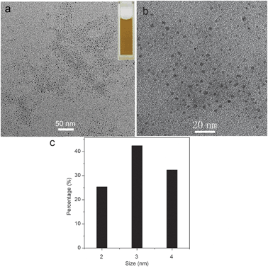 | ||
| Fig. 1 (a) Low, (b) high magnification TEM images, and (c) the corresponding particle size distribution histogram of the products obtained by heating Cu(OAc)2 solution at 180 °C for 40 min in the presence of PQ11 (inset: the photograph of CuO dispersion in water). | ||
Fig. 2 shows the XRD pattern of the nanoparticles thus obtained. It is seen that a series of diffraction peaks at 2θ of 32.4°, 35.6°, 38.8°, 48.9°, 53.3°, 58.2°, 61.6°, and 66.3° are observed, which are assigned to the (110), (002), (200), (−202), (020), (202), (−113), and (022) planes of monoclinic CuO (JCPDS 45-0397), respectively.23 Note that except for these CuO peaks, no other peaks corresponding to Cu or Cu2O are observed. These results indicate the successful preparation of CuO nanoparticles. It is important to point out that these CuO nanoparticles can be very stable for several months without the observation of any floating or precipitated particles, indicating the excellent stabilizing ability of PQ11.24–26
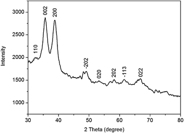 | ||
| Fig. 2 XRD pattern of CuO nanoparticles thus obtained. | ||
The surface composition and elemental analysis for the overall composition of the resultant nanoparticles were characterized by an XPS technique. The XPS spectrum of the nanoparticles shown in Fig. 3 exhibits three peaks at 284.6, 400.9 and 531.0 eV, which are attributed to C1s, N1s, and O1s, respectively.27 Other three peaks at 933.3, 121.1 and 77.0 eV associated with Cu2p, Cu3s and Cu3p, respectively, are also observed.28 XPS results show that nanoparticles thus obtained contain C, N, O, and Cu elements, indicating that these CuO nanoparticles are capped by PQ11. It is reported that heating aqueous Cu(OAc)2 and urea solution produces CuO particles with large size.29 The presence of PQ11, however, leads to CuO nanoparticles with small particle size in our present study, suggesting that PQ11 indeed serves as an effective capping agent preventing uncontrollable growth of CuO nanoparticles. Furthermore, the Cu2p spectrum of these nanoparticles (Fig. 4) exhibits a copper 2p1/2 peak at 953.5 eV and a 2p3/2 peak at 933.5 eV, which are 1.3 ± 0.2 eV higher than the peak positions for Cu(0) metal and are attributed to Cu(II),28 indicating that the products are CuO nanoparticles.
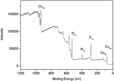 | ||
| Fig. 3 XPS spectrum of CuO nanoparticles thus obtained. | ||
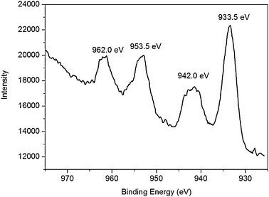 | ||
| Fig. 4 Cu2p spectrum of CuO nanoparticles thus obtained. | ||
Note that as-formed dispersion can form stable films on bare GCE, eliminating the use of an immobilization support matrix1 or time-consuming steps of surface modification of both GCE and the CuO nanoparticles.30 In order to demonstrate the sensing application of the CuO nanoparticles, we constructed a nonenzymatic glucose sensor by deposition of the aqueous dispersion of CuO nanoparticles on a GCE surface. Fig. 5a shows the CVs of bare GCE and CuO nanoparticles modified GCE (designated as CuO/GCE) in 0.1 M NaOH in the presence of 1 mM of glucose at a scan rate of 0.02 V s−1. We also performed one control experiment by studying the CV behavior of CuO/GCE in the absence of glucose. It is seen that the response of bare GCE toward the oxidation of glucose is pretty weak. In contrast, CuO nanoparticles exhibit a remarkable catalytic current peak about 78.8 μA in an intensity at 0.57 V; however, they exhibit relatively weak current signal in the absence of glucose. The CV behavior of the CuO particles with large size obtained in the absence of PQ11 toward oxidation of glucose was also examined, as shown in Fig. S2 (ESI†). It suggests that the CuO nanoparticles with small particle size exhibit better catalytic activity than those with large particle size. It is well known that nanoparticles exhibit better electrochemical activity than their bulky counterparts due to their relatively small particle size leading to high specific surface area, decrease in overpotentials and possibility of promoting electron transfer reactions.31 The notable catalytic performance of the CuO nanoparticles in our present study can be attributed to their small particle size nature. Note that the CuO nanoparticles dispersion forms highly stable films which do not come off when immersed in working solution, indicating that PQ11 provides an effective immobilization support matrix for the CuO nanoparticles on GCE. Fig. 5b shows the typical current–time plot of the CuO/GCE in 0.1 M NaOH solution on successive step-wise change of glucose concentrations. When an aliquot of glucose was added into the NaOH solution with stirring, CuO/GCE responded rapidly to the substrate and the current rose steeply to reach a stable value. The anode current of the sensor increased dramatically and achieved 95% of the steady state current within 2 s, revealing a fast amperometric response behavior. The inset in Fig. 5b shows the calibration curve of the sensor. The linear detection range is estimated to be from 5 μM to 2.3 mM (r = 0.994), and the detection limit is estimated to be 0.5 μM at a signal-to-noise ratio of 3. It is found that the sensitivity of the present non-enzymatic glucose sensor is 1397 μA mM−1 cm−2, which is higher than other similar glucose detecting constructions.20,32,33 The performance of our glucose sensor is also compared with those previously published non-enzymatic glucose sensors based on CuO, as shown in Table 1. Note that our present sensing system gives a lower detection limit than CuO nanoparticles on multi-walled carbon nanotube (MWCNT) arrays-based system (0.8 μM),22 CuO nanospheres/GCE (1 μM),20 CuO flowers/graphite electrode (4 μM)32 and CuO nanofibres/GCE (0.8 μM).33 The relative standard deviation (RSD) of the amperometric response to 100 μM of glucose at +0.55 V is 2.8% for 5 successive measurements, indicating the good reproducibility of CuO/GCE.
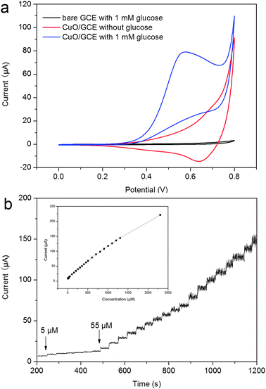 | ||
| Fig. 5 (a) CVs of a bare GCE, a CuO/GCE in the presence of 1 mM of glucose, and the CuO/GCE in the absence of glucose in 0.1 M NaOH (scan rate: 0.02 V s−1), and (b) typical steady-state response of the CuO/GCE to successive injection of glucose into the 0.1 M NaOH solution under stirring. The inset was the calibration curve (applied potential: +0.55 V). | ||
| Type of electrodes | Performance | Ref. | |
|---|---|---|---|
| LOD/μM | Linear range | ||
| Nafion/CuO nanospheres/GCE | 1 | 50 μM–2.55 mM | 20 |
| CuO/MWCNT | 0.8 | 0.2 mM–3 mM | 22 |
| CuO/MWCNT | 0.2 | 0.4 μM–1.2 mM | 18 |
| Nafion/CuO flowers/graphite | 4 | 4 μM–8 mM | 31 |
| Nafion/CuO nanofibres/GCE | 0.8 | 0.6 μM–2.5 mM | 32 |
| CuO nanoparticles/GCE | 0.5 | 5 μM–2.3 mM | This work |
Because the easily oxidative species such as DA, AA, and UA usually co-exist with glucose in human blood, the electrochemical response of the interfering species was also examined at the CuO/GCE, as shown in Fig. 6. It is seen that a well-defined glucose response was obtained, while insignificant responses were observed for interfering species. These observations indicate that our present sensor shows high selectivity for glucose detection in comparison to the normally co-existing electroactive species.
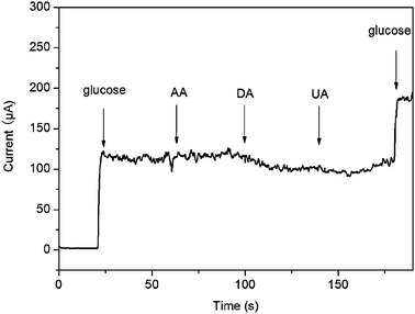 | ||
| Fig. 6 Interference test of the sensor in 0.1 M NaOH at +0.55 V with 1 mM glucose and other interferents including 0.1 mM AA, 0.1 mM DA and 0.1 mM UA. | ||
In an attempt to explore the glucose sensor for practical application, the sensor was applied to determine glucose in human blood serum. The electrolyte solution containing 1.5 mL of the serum sample and 3.5 mL of 0.1 M NaOH is used for amperometric detection. It is seen that the response current increases with increase in the concentration of glucose from 50 to 250 μM, as shown in Fig. 7a. Fig. 7b shows that the anode currents increase linearly with increased glucose concentrations (R = 0.999). The RSD of the amperometric current response to 100 μM glucose is 3.6% for 5 successive measurements. Thus, this sensor holds great promise for real sample detection application.
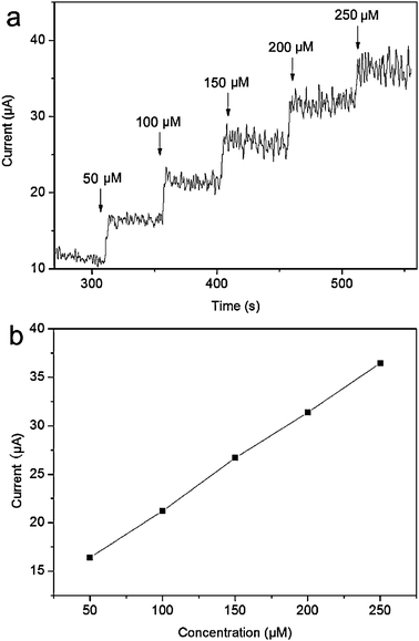 | ||
| Fig. 7 (a) The typical steady-state response of the CuO/GCE to successive injection of 50 μM glucose into the air-saturated 0.1 M NaOH solution containing 1.5 mL of blood serum under stirring and (b) the corresponding calibration curve (applied potential: +0.55 V). | ||
The long-term stability of the prepared glucose sensor is a critical factor in practical detection application. The stability was examined by periodical measurements of the sensor responses to 100 μM glucose. The variation of the amperometric response current at the CuO/GCE decreases to about 98% of its initial response current on the 5th day and about 95% on the 10th day, as shown in Fig. S3 (ESI†). The good stability of the CuO/GCE can be attributed to both the chemical stability of CuO in basic solution and the formation of stable CuO nanoparticle-containing film on GCE with the aid of PQ11.24–26
Conclusion
We have developed a simple method for preparation of highly stable CuO nanoparticles with the use of PQ11 as a stabilizing agent. It suggests that the CuO nanoparticles thus formed exhibit notable catalytic performance for oxidation of glucose and the sensor constructed shows good response to glucose in buffer and human blood serum. Our present study provides us a simple preparative strategy toward CuO nanoparticles for glucose sensing and other applications.Acknowledgements
This work was supported by the National Natural Science Foundation of China (No. 21175129) and the National Basic Research Program of China (No. 2011CB935800).References
- S. R. Lee, Y. T. Lee, K. Sawada, H. Takao and M. Ishida, Biosens. Bioelectron., 2008, 24, 410 CrossRef CAS.
- D. W. Schmidtke and A. Heller, Anal. Chem., 1998, 70, 2149 CrossRef CAS.
- Y. Song, K. Qu, C. Zhao, J. Ren and X. Qu, Adv. Mater., 2010, 22, 2206 CrossRef CAS.
- J. Wang, Chem. Rev., 2008, 108, 814 CrossRef CAS.
- C. Xia and W. Ning, Electrochem. Commun., 2010, 13, 1581 CrossRef.
- E. I. Khatib and K. M. R. M. A. Hameed, Biosens. Bioelectron., 2011, 26, 3542 CrossRef.
- Y. Lin, F. Lu and Z. Ren, Nano Lett., 2004, 4, 191 CrossRef CAS.
- S. Liu, J. Tian, L. Wang, Y. Luo, W. Lu and X. Sun, Biosens. Bioelectron., 2011, 26, 4491 CrossRef CAS.
- Y. Zhang, G. Chang, S. Liu, W. Lu, J. Tian and X. Sun, Biosens. Bioelectron., 2011, 28, 344 CrossRef CAS.
- W. Lu, Y. Luo, G. Chang and X. Sun, Biosens. Bioelectron., 2011, 26, 4791 CrossRef CAS.
- C. Shan, H. Yang, D. Han, Q. Zhang, A. Ivaska and L. Niu, Biosens. Bioelectron., 2010, 25, 1070 CrossRef CAS.
- S. J. Park, H. K. Boo and T. D. Chung, Anal. Chim. Acta, 2006, 556, 46 CrossRef CAS.
- R. Wilson and A. P. F. Turner, Biosens. Bioelectron., 1992, 7, 165 CrossRef CAS.
- M. Tominaga, T. Shimazoe, M. Nagashima, H. Kusuda, A. Kubo, Y. Kuwahara and I. Taniguchi, J. Electroanal. Chem., 2006, 590, 37 CrossRef CAS.
- H. Wu, W. Cao, Y. Li, G. Liu, Y. Wen, H. Yang and S. Yang, Electrochim. Acta, 2011, 55, 3734 CrossRef.
- X. Zhang, G. Wang, W. Zhang, Y. Wei and B. Fang, Biosens. Bioelectron., 2009, 24, 3395–3398 CrossRef CAS.
- F. Jiang, S. Wang, J. Lin, H. Jin, L. Zhang, S. Huang and J. Wang, Electrochem. Commun., 2011, 13, 363 CrossRef CAS.
- L. Jiang and W. Zhang, Biosens. Bioelectron., 2010, 25, 1402 CrossRef CAS.
- C. Li, Y. Su, S. Zhang, X. Lv, H. Xia and Y. Wang, Biosens. Bioelectron., 2010, 26, 903 CrossRef CAS.
- E. Reitz, W. Jia, M. Gentile, Y. Wang and Y. Lei, Electroanalysis, 2008, 22, 2482 CrossRef.
- Y. Li, Y. Wei, G. Shi, Y. Xian and L. Jin, Electroanalysis, 2011, 23, 497 CrossRef CAS.
- J. Yang, L. Jiang, W. Zhang and S. Gunasekaran, Talanta, 2010, 82, 25 CrossRef CAS.
- M. Yang and J. He, J. Colloid Interface Sci., 2011, 355, 15 CrossRef CAS.
- G. Chang, Y. Luo, W. Lu, F. Liao and X. Sun, J. Nanopart. Res., 2011, 13, 2689 CrossRef CAS.
- S. Liu, J. Tian, L. Wang, H. Li, Y. Zhang and X. Sun, Macromolecules, 2010, 43, 10078 CrossRef CAS.
- W. Lu, F. Liao, Y. Luo, G. Chang and X. Sun, Electrochim. Acta, 2011, 56, 2295 CrossRef CAS.
- S. Liu, J. Tian, L. Wang and X. Sun, Carbon, 2011, 49, 3158 CrossRef CAS.
- M. Durando, R. Morrish and A. J. Muscat, J. Am. Chem. Soc., 2008, 130, 16659 CrossRef CAS.
- C. Chen, J. Qu, C. Cao, F. Niu and W. Song, J. Mater. Chem., 2011, 21, 5774 RSC.
- Multilayer thin films, ed. G. Decher and J. B. Schelenoff, Wiley-VCH, Weinheim, 2002 Search PubMed.
- X. Luo, A. Morrin, A. J. Killard and M. R. Smyth, Electroanalysis, 2006, 18, 319 CrossRef CAS.
- X. Wang, C. Hu, H. Liu, G. Du, X. He and Y. Xi, Sens. Actuators, B, 2010, 144, 220 CrossRef.
- W. Wang, L. Zhang, S. Tong, X. Li and W. Song, Biosens. Bioelectron., 2009, 25, 708 CrossRef CAS.
Footnote |
| † Electronic supplementary information (ESI) available. See DOI: 10.1039/c2cy00453d |
| This journal is © The Royal Society of Chemistry 2012 |