One-pot synthesis of CuO nanoflower-decorated reduced graphene oxide and its application to photocatalytic degradation of dyes†
Sen
Liu
a,
Jingqi
Tian
ab,
Lei
Wang
a,
Yonglan
Luo
a and
Xuping
Sun
*a
aState Key Lab of Electroanalytical Chemistry, Changchun Institute of Applied Chemistry, Chinese Academy of Sciences, Changchun 130022, Jilin, P. R. China. E-mail: sunxp@ciac.jl.cn; Fax: +86-431-85262065; Tel: +86-431-85262065
bGraduate School of the Chinese Academy of Sciences, Beijing 100039, China
First published on 2nd November 2011
Abstract
In this paper, we demonstrate our recent finding that CuO nanoflower-decorated reduced graphene oxide (CuONF/rGO) nanocomposites can be successfully prepared by heating the mixture of Cu salts and GO in the presence of poly[(2-ethyldimethylammonioethyl methacrylate ethyl sulfate)-co-(1-vinylpyrrolidone)] (PQ11) and urea for the first time. Several analytical techniques, including UV-vis spectroscopy, Raman spectroscopy, X-ray diffraction (XRD), transmission electron microscopy (TEM), and X-ray photoelectron spectroscopy (XPS) have been used to characterize the resulting CuONF/rGO nanocomposites. We further demonstrated that such CuONF/rGO nanocomposites can serve as an effective photocatalyst for degradation of rhodamine B (RhB) under UV irradiation. It also suggests that these CuONF/rGO nanocomposites exhibit a higher photocatalytic activity toward degradation of RhB than CuO nanoparticles or rGO samples.
Introduction
Graphene, a monolayer of sp2-bonded carbon atoms tightly packed into a two-dimensional (2D) honeycomb lattice, and characterized as “the thinnest material in our universe”, has recently received considerable attention.1 Because of its high surface area (∼2600 m2 g−1), high chemical stability, and unique electronic, mechanical properties, graphene has great promise for potential applications in nanoelectronics, composites, Li ion batteries, sensors etc.2 Compared to other methods for production of graphene, the strategy based on chemical reduction of graphene oxide (GO) has great advantages of low cost and bulk quantity production and reduced graphene oxide (rGO) thus formed has been widely used for preparation of graphene-based nanocomposites.3 Particularly, metal or metal oxide/rGO composites have attracted considerable interest because of the combination of remarkable unusual properties of metal or metal oxide with graphene and hence their synthesis and application have become of scientific and technological importance.4 Recent research has shown that graphene is a promising candidate for preparation of graphene-based hybrids for adsorption and separation of dyes and photocatalytic degradation of dyes due to its high surface area and π-rich structure.5 Indeed, graphene has been successfully decorated with numerous inorganic materials including gold, Ag@AgCl, ZnO, TiO2, Cu salts by various methods, leading to nanocomposites with photocatalytic activity for degradation of dyes.6CuO as a p-type semiconducting material has received considerable attention due to its wide applications in many important fields such as gas sensors, magnetic phase transitions, superconductors and photocatalysts.7 Inspired by enhancement of the properties of nanoparticles through anchoring them onto graphene sheets, researchers have attempted to prepare CuO nanoparticle decorated graphene sheets. Up to now, however, only very limited methods have been developed, including heating an aqueous solution of Cu salts in the presence of graphene synthesized by an arc discharge method,8asolvothermal synthesis of CuO/GO and the subsequent reduction of GO by hydrazine vapor,8b and chemical reduction of Cu salts in an aqueous solution in the presence of hydrogen induced exfoliated graphene (HEG).8c Unfortunately, all these above-mentioned methods suffer from more or less drawbacks such as the involvement of two steps in the preparation and thus complex and time-consuming, high cost and poor dispersing ability of resulting nanocomposites, which limit their wide applications. Accordingly, developing simple and economical methods for preparation of CuO/graphene nanocomposites is highly desired.
In this study, we developed a facile strategy for one-step preparation of well-stable aqueous dispersion of CuO nanoflower-decorated rGO (CuONF/rGO) nanocomposites, carried out by heating the mixture of Cu salts and GO in the presence of poly[(2-ethyldimethylammonioethyl methacrylate ethyl sulfate)-co-(1-vinylpyrrolidone)] (PQ11) and urea. It suggests that the resulting CuONF/rGO nanocomposites can serve as an effective photocatalyst for degradation of rhodamine B (RhB) under UV irradiation and their photocatalytic activity is higher than that of CuO nanoparticles or rGO samples.
Experimental section
PQ11, graphite powder, Cu(OAc)2·H2O, urea, and H2O2 (30%) were purchased from Aladin Ltd. (Shanghai, China). NaNO3, RhB, H2SO4 (98%), and KMnO4 were purchased from Beijing Chemical Corp. All chemicals were used as received without further purification. The water used throughout all experiments was purified through a Millipore system.UV-vis spectra were obtained on a UV5800 spectrophotometer. Raman spectra were obtained on a J-Y T64000 Raman spectrometer with 514.5 nm wavelength incident laser light. Powder X-ray diffraction (XRD) datum was recorded on a RigakuD/MAX 2550 diffractometer with Cu Kα radiation (λ = 1.5418 Å). X-Ray photoelectron spectroscopy (XPS) analysis was measured on an ESCALABMK II X-ray photoelectron spectrometer using Mg as the exciting source. Transmission electron microscopy (TEM) measurements were made on a Hitachi H-8100 electron microscope (Hitachi, Tokyo, Japan) with an accelerating voltage of 200 kV. The sample for TEM characterization was prepared by placing a drop of colloidal solution on a carbon-coated copper grid and drying at room temperature.
GO was prepared from natural graphite powder through a modified Hummers' method.9 In a typical synthesis, 1 g of graphite was added into 23 mL of H2SO4, followed by stirring at room temperature over a period of 24 h. After that, 100 mg of NaNO3 was introduced into the mixture and stirred for 30 min. Subsequently, the mixture was kept below 5 °C using an ice bath, and 3 g of KMnO4 was slowly added into the mixture. After being heated to 35–40 °C, the mixture was stirred for another 30 min. After that, 46 mL of water was added into the above mixture during a period of 25 min. Finally, 140 mL of water and 10 mL of 30% H2O2 were added into the mixture to stop the reaction. After the unexploited graphite in the resulting mixture was removed by centrifugation, as-synthesized GO was dispersed into individual sheets in distilled water at a concentration of 0.5 mg mL−1 with the aid of ultrasound for further use.
CuONF/rGO nanocomposites were prepared by heating the mixture of Cu(OAc)2·H2O and GO in the presence of PQ11 and urea. In a typical synthesis, 26 mg of Cu(OAc)2·H2O and 16 mg of urea were added into 10 mL of ethanol, followed by addition of 1 mL of 0.67 M PQ11 aqueous solution and 1 mL of GO (0.5 mg mL−1) solution. After sonication at room temperature for 20 min, the solution was transferred into an autoclave and then heated at 180 °C for 40 min. The solid products were obtained by centrifugation, washed by water and ethanol, and dispersed into water for further characterization and use. The rGO and CuO nanoparticles were also prepared in a similar method without adding Cu(OAc)2·H2O and GO, respectively.
The photocatalytic activity of the CuONF/rGO nanocomposites, CuO nanoparticles, and rGO was evaluated by the degradation of a model pollutant RhB. For the degradation of RhB, the reactor was placed in a sealed black box with an open top and was irradiated by a UV light source with a 150 W xenon lamp. In a typical run, 100 μL of catalyst dispersion was added into 3 mL of H2O, followed by addition of 100 μL of H2O2 and 10 μL of RhB solution (2 mg mL−1 in ethanol). The concentration of RhB in the solution was determined using a UV5800 spectrophotometer by collecting the absorbance of RhB at 553 nm.
Results and discussion
Fig. 1 shows the Raman spectra of GO and the products obtained by heating the mixture of Cu(OAc)2·H2O and GO in the presence of PQ11 and urea. It is well-known that graphene obtained by chemical reduction of GO exhibits two characteristic main peaks: the D band at ∼1350 cm−1, arising from a breathing mode of κ-point photons of A1g symmetry; the G band at 1575 cm−1, arising from the first order scattering of the E2g phonon of sp2 C atoms.10 In our present study, it is seen that both GO and the products exhibit a D band at 1347 cm−1 and a G band at 1604 cm−1. It is also found that the products show relatively higher intensity of D to G band (0.96) than that of GO (0.77). These observations confirm the formation of new graphitic domains after the heat treatment process. Fig. 1 inset shows the photographs of aqueous dispersion of GO (left) and the products thus obtained (right), revealing a distinct color change from pale-yellow to black after heat treatment. Such observation provides another piece of evidence to support the formation of rGO.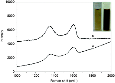 | ||
| Fig. 1 Raman spectra of GO (a) and products thus obtained (b). Inset: photographs of GO (left) and products (right) in aqueous solution. | ||
The XRD pattern of products thus obtained as shown in Fig. 2 exhibits that three diffraction peaks at 2θ of 35.8, 39.2 and 62.0° are observed, which are assigned to the (002), (200) and (−113) planes of monoclinic CuO (JCPDS 45-0397), respectively.11 Note that except for these CuO peaks, no other peaks corresponding to Cu or Cu2O are observed. All these observations indicate that CuO samples were successfully prepared by heat treatment of Cu(OAc)2 solution in the presence of PQ11 and urea.
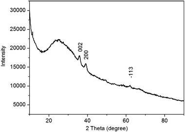 | ||
| Fig. 2 XRD pattern of products thus obtained. | ||
The surface composition and element analysis for the overall composition of the resulting products were characterized by an XPS technique. Fig. 3 shows the XPS spectrum of products, revealing three peaks at 285.5, 400.9 and 531.0 eV, which are attributed to C1s, N1s, and O1s, respectively.12 Other two peaks at 933.3 and 77.0 eV associated with Cu2p and Cu3p, respectively, are also observed.13XPS results show that products thus obtained are formed from Cu(OAc)2 and GO, while the observation of N element in the XPS spectrum indicates the presence of PQ11 on the surface of such products. It is also found that the O1s intensity of products is significantly decreased compared with that of GO, suggesting the loss of oxygen in GO after the heat treatment.14
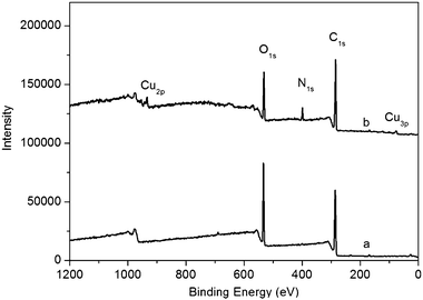 | ||
| Fig. 3 XPS spectra of GO (a) and products thus obtained (b). | ||
Fig. 4 shows the C1sspectra of GO and the products, respectively. The C1sspectra of GO and the products could be deconvoluted into three peaks at 284.5, 286.6, and 288.4 eV, which are associated with C–C, C–O, and C![[double bond, length as m-dash]](https://www.rsc.org/images/entities/char_e001.gif) O, respectively. It is obviously seen that the peak intensity of C–O and C
O, respectively. It is obviously seen that the peak intensity of C–O and C![[double bond, length as m-dash]](https://www.rsc.org/images/entities/char_e001.gif) O is strong in GO (Fig. 4a); in contrast, after heat treatment, the peak intensity of C–O and C
O is strong in GO (Fig. 4a); in contrast, after heat treatment, the peak intensity of C–O and C![[double bond, length as m-dash]](https://www.rsc.org/images/entities/char_e001.gif) O in the products tremendously reduced (Fig. 4b). In addition, it is also seen that a new peak at 286 eV attributed to the C–N band is observed, further confirming the presence of PQ11. All the observations suggest that the most oxygen-containing functional groups are successfully removed after heat treatment.15
O in the products tremendously reduced (Fig. 4b). In addition, it is also seen that a new peak at 286 eV attributed to the C–N band is observed, further confirming the presence of PQ11. All the observations suggest that the most oxygen-containing functional groups are successfully removed after heat treatment.15
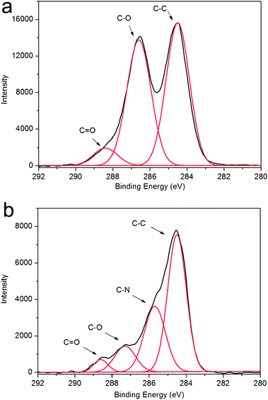 | ||
| Fig. 4 C1sspectra of GO (a) and products thus obtained (b). | ||
Fig. 5 shows the Cu2p spectrum of products thus obtained. It is seen that the Cu2p spectrum exhibits a copper 2p1/2 peak at 953.3 eV and a 2p3/2 peak at 933.7 eV, which are 1.3 ± 0.2 eV higher than the peak positions for Cu(0) metal and are attributed to oxidized Cu(II).16 Strong shake-up satellite peaks are also observed at ∼942.0 eV and an overlapping series at ∼962.1 eV, further confirming the presence of Cu(II) on the surface.16 All these observations further confirm the formation of CuO.
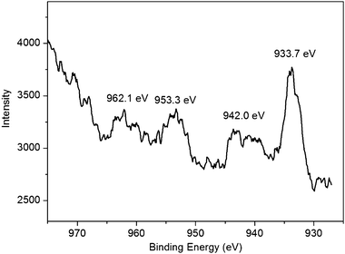 | ||
| Fig. 5 Cu2p spectrum of products thus obtained. | ||
Fig. 6a shows the low magnification TEM image of the products, indicating the formation of CuO nanoparticle-decorated rGO. The high magnification TEM image (Fig. 6b) further reveals that such nanoparticle consists of smaller nanoparticles and is flower in shape, suggesting the formation of CuONF/rGO. It is worthwhile mentioning that the dispersion of the resulting CuONF/rGO can be well-stable for several weeks without the observation of any floating or precipitate particles, owing to the presence of PQ11 which has been used as an effective stabilizing agent for rGO and metal nanoparticles in our previous studies.17
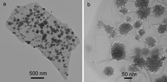 | ||
| Fig. 6 TEM images of CuONF/rGO nanocomposites. | ||
It should be noted that GO has been successfully reduced by heating the mixture of GO and Cu salts in the presence of PQ11 and urea at 180 °C for 40 min. The production of rGO from GO can be attributed to the various factors in the present study, including the high temperature used,18 the heat treatment of GO by alcohol,19 the treatment of GO by alkaline formed by hydrolysis of urea20 as well as the reduction of GO by the reducing agent PQ11.11b,c All the above factors play an important role in reduction of GO, and thus, a short time is required to complete reduction of GO. We have found that CuO nanoparticles with diameter of 2–4 nm were obtained by heating the mixture of Cu salts in the presence of PQ11, but the products prepared in the absence of PQ11 are nanoparticle aggregates about 50–100 nm in size,21 indicating that PQ11 serves as an effective stabilizing agent. Furthermore, our previous report also suggests that PQ11 is a good stabilizing agent for formation of rGO.11a It is also found in our present study that heat treatment of the mixture of Cu salts and GO in the absence of PQ11 results in the formation of aggregates of rGO and CuO (Fig. S1, ESI†). All the above observations suggest that PQ11 plays an important role in the formation of CuONF/rGO, serving as an effective stabilizing agent for formation of CuO nanoparticles and a good reducing and stabilizing agent for formation of stable rGO dispersion. Due to the strong interaction between PQ11 and CuO nanoparticles as well as rGO, an assembly process occurs, resulting in the formation of a CuO nanoflower on the surface of rGO. The possible formation mechanism is proposed as follows: CuO nanoparticles and rGO are formed from Cu salts and GO in the presence of PQ11 and then CuO nanoparticles thus formed are subsequently assembled into CuONF on rGO with the aid of PQ11. Scheme 1 presents a scheme (not to scale) to illustrate the formation of CuONF/rGO nanocomposites from GO and Cu salts in the presence of PQ11 by a one-pot heat treatment route.
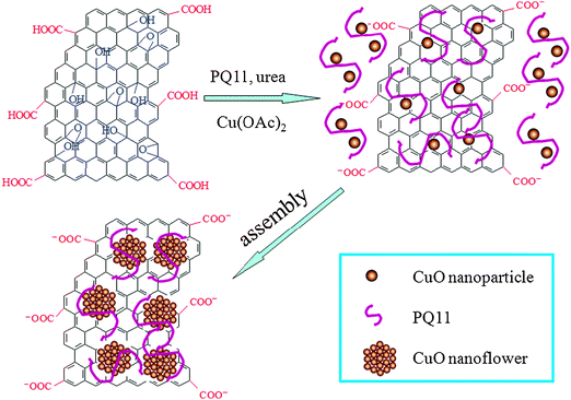 | ||
| Scheme 1 A scheme (not to scale) to illustrate the formation of CuONF/rGO nanocomposites from GO and Cu salts by a one-pot heat treatment method. | ||
As a demonstration of application of such CuONF/rGO, RhB was chosen as a representative organic dyestuff to evaluate the photocatalytic performance. Fig. 7a shows the photocatalytic performance of various catalysts for degradation of RhB in the presence of H2O2. In the absence of a photocatalyst, RhB was degraded slowly by H2O2. It is seen that the degradation of RhB was greatly enhanced in the presence of CuONF/rGO, indicating the excellent photocatalytic activity of CuONF/rGO. However, CuONF/rGO exhibits no obvious photocatalytic activity in the absence of H2O2 (Fig. S2, ESI†). Furthermore, the degradation of RhB was slightly enhanced in the presence of CuO nanoparticles or rGO, which is attributed to the catalytic oxidation of RhB by CuO and adsorption of RhB by rGO, respectively. It should be noted that the high photocatalytic activity of CuONF/rGO can be attributed to the fast adsorption of RhB by π–π stacking interactions between RhB and the π-conjugation system of CuONF/rGO as well as the two-dimensional planar structure of CuONF/rGO, leading to the fast degradation of RhB.6eFig. 7b shows the typical time-dependent UV-vis absorption spectra of RhB solution during the photodegradation in the presence of CuONF/rGO with the aid of H2O2. It is seen that RhB exhibits a maximum absorption peak at around 553 nm. Note that the color of RhB solutions becomes less intense, and the intensity of absorption spectra decreases gradually with increasing irradiation time, indicating that a strong oxidation of RhB has occurred in the presence of CuONF/rGO under UV irradiation. All these observations indicate that CuONF/rGO nanocomposites exhibit excellent performance for degradation of RhB. According to the previous report,7e the possible mechanism for degradation of RhB may be proposed as follows: the photodecomposition of H2O2 to form a certain amount of OH· in the presence of CuO nanoflower first, and then these OH species oxidize degradation of RhB into CO2, H2O and other mineralization through a series of redox reactions.
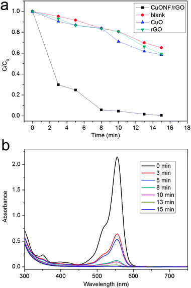 | ||
| Fig. 7 Photodegradation of RhB (a) over CuONF/rGO (■), without catalyst (●), over CuO nanoparticles (▲), and rGO (▼) (b) under UV light irradiation. | ||
Conclusions
In summary, CuONF/rGO nanocomposites have been successfully prepared by heating the mixture of Cu salts and GO in the presence of PQ11 by a one-pot route. The photocatalytic degradation of RhB by CuONF/rGO nanocomposites in the presence of H2O2 has also been demonstrated and it revealed that the CuO nanoflowers contained therein exhibit notable catalytic activity toward the degradation of RhB. Our present findings provide us a simple approach to the facile production of metal oxide decorated rGO on a large scale for photocatalytic applications.Acknowledgements
This work was supported by National Basic Research Program of China (No. 2011CB935800) and the National Natural Science Foundation of China (No. 21175129).References
- (a) K. S. Novoselov, S. V. Geim, S. V. Morozov, D. Jiang, Y. Zhang, S. V. Dubonos, I. V. Grigorieva and A. A. Firsov, Science, 2004, 306, 666 CrossRef CAS; (b) M. J. Allen, V. C. Tung and R. B. Kaner, Chem. Rev., 2010, 110, 132 CrossRef CAS; (c) X. Huang, Z. Yin, S. Wu, X. Qi, Q. He, Q. Zhang, Q. Yan, F. Boey and H. Zhang, Small, 2011, 7, 1876 CrossRef CAS; (d) X. Huang, X. Qi, F. Boey and H. Zhang, Chem. Soc. Rev., 2012 10.1039/C1CS15078B.
- (a) Y. Zhang, Y.-W. Tan, H. L. Stormer and P. Kim, Nature, 2005, 438, 201 CrossRef CAS; (b) S. Stankovich, D. A. Dikin, G. H. B. Dommett, K. M. Kohlhaas, E. J. Zimney, E. A. Stach, R. D. Piner, S. T. Nguyen and R. S. Ruoff, Nature, 2006, 442, 282 CrossRef CAS; (c) E. Yoo, J. Kim, E. Hosono, H.-S. Zhou, T. Kudo and I. Homa, Nano Lett., 2008, 8, 2277 CrossRef CAS; (d) C. Shan, H. Yang, J. Song, D. Han, A. Ivaska and L. Niu, Anal. Chem., 2009, 81, 5603 CrossRef.
- (a) Y. Xu, H. Bai, G. Lu, C. Li and G. Q. Shi, J. Am. Chem. Soc., 2008, 130, 5856 CrossRef CAS; (b) S. Stankovich, R. D. Piner, X. Chen, N. Wu, S. T. Nguyen and R. S. Ruoff, J. Mater. Chem., 2006, 16, 155 RSC; (c) D. Li, M. B. Müller, S. Gilje, R. B. Kaner and G. G. Wallace, Nat. Nanotechnol., 2008, 3, 101 CrossRef CAS; (d) S. Liu, J. Tian, L. Wang, Y. Luo, W. Lu and X. Sun, Biosens. Bioelectron., 2011, 26, 4491 CrossRef CAS.
- (a) R. Muszyski, B. Serger and P. V. Kamat, J. Phys. Chem. C, 2008, 112, 5263 CrossRef; (b) X. Zhou, X. Huang, X. Qin, S. Wu, C. Xue, F. Y. C. Boey, Q. Yan, P. Chen and H. Zhang, J. Phys. Chem. C, 2009, 113, 10842 CrossRef CAS; (c) I. V. Lightcap, T. H. Kosel and P. V. Kamat, Nano Lett., 2010, 10, 577 CrossRef CAS; (d) S. Liu, J. Tian, L. Wang and X. Sun, Carbon, 2011, 49, 3158 CrossRef CAS; (e) S. Liu, L. Wang, J. Tian, W. Lu, Y. Zhang, X. Wang and X. Sun, J. Nanopart. Res., 2011, 13, 4731 CrossRef CAS; (f) J. Zhu, G. Zeng, F. Nie, X. Xu, S. Chen, Q. Han and X. Wang, Nanoscale, 2010, 2, 988 RSC; (g) X. Huang, S. Z. Li, Y. Z. Huang, S. X. Wu, X. Z. Zhou, S. Z. Li, C. L. Gan, F. Boey, C. A. Markin and H. Zhang, Nat. Commun., 2011, 2, 292 CrossRef; (h) X. Huang, Z. Yin, S. Wu, X. Qi, Q. He, Q. Zhang, Q. Yan, F. Boey and H. Zhang, Small, 2011, 7, 1876 CrossRef CAS.
- (a) B. Li, H. Cao, G. Yin, Y. Lu and J. Yin, J. Mater. Chem., 2011, 21, 10645 RSC; (b) C. Lu, H. Yang, C. Zhu, X. Chen and G. Chen, Angew. Chem., Int. Ed., 2009, 48, 4785 CrossRef CAS; (c) H. Liu, J. Gao, M. Xue, N. Zhu, M. Zhang and T. Cao, Langmuir, 2009, 25, 12006 CrossRef CAS; (d) H. Sun, L. Cao and L. Lu, Nano Res., 2011, 4, 550 CrossRef CAS; (e) S. Yang, S. Chen, Y. Chang, A. Cao, Y. Liu and H. Wang, J. Colloid Interface Sci., 2011, 359, 24 CrossRef CAS; (f) S. Liu, H. Li, L. Wang, J. Tian and X. Sun, J. Mater. Chem., 2011, 21, 339 RSC; (g) S. Liu, L. Wang, J. Tian, Y. Luo, X. Zhang and X. Sun, J. Colloid Interface Sci., 2011, 363, 615 CrossRef CAS.
- (a) M. Zhu, P. Chen and M. Liu, ACS Nano, 2011, 5, 4529 CrossRef CAS; (b) J. Zhang, Z. Xiong and X. S. Zhao, J. Mater. Chem., 2011, 21, 3634 RSC; (c) Z. Xiong, L. Zhang and X. S. Zhao, Chem.–Eur. J., 2011, 17, 2428 CrossRef CAS; (d) Z. Xiong, L. Zhang, J. Ma and X. S. Zhao, Chem. Commun., 2010, 46, 6099 RSC; (e) H. Zhang, X. Lv, Y. Li, Y. Wang and J. Li, ACS Nano, 2010, 4, 380 CrossRef CAS; (f) O. Akhavan, ACS Nano, 2010, 4, 4174 CrossRef CAS; (g) I. V. Lightcap, T. H. Kosel and P. V. Kamat, Nano Lett., 2010, 10, 577 CrossRef CAS.
- (a) C. D. Cavellin and M. Lagues, Nature, 2001, 414, 434 CrossRef; (b) L.-C. Jiang and W.-D. Zhang, Biosens. Bioelectron., 2010, 25, 1402 CrossRef CAS; (c) S. Gao, S. Yang, J. Shu, S. Zhang, Z. Li and K. Jiang, J. Phys. Chem. C, 2008, 112, 19324 CrossRef CAS; (d) M.-J. Song, S. W. Hwang and D. Whang, Talanta, 2010, 80, 1648 CrossRef CAS; (e) H. Yu, J. Yu, S. Liu and S. Mann, Chem. Mater., 2007, 19, 4327 CrossRef CAS.
- (a) B. Wang, X.-L. Wu, C.-Y. Shu, Y.-G. Guo and C.-R. Wang, J. Mater. Chem., 2010, 20, 10661 RSC; (b) Y. J. Mai, X. L. Wang, J. Y. Xiang, Y. Q. Qiao, D. Zhang, C. D. Gu and J. P. Tu, Electrochim. Acta, 2011, 56, 2306 CrossRef CAS; (c) T. T. Baby and R. Sundara, J. Phys. Chem. C, 2011, 115, 8527 CrossRef CAS.
- (a) W. S. Hummers, Jr. and R. Offeman, J. Am. Chem. Soc., 1958, 80, 1339 CrossRef; (b) S. Liu, J. Tian, L. Wang and X. Sun, J. Nanopart. Res., 2011, 13, 4539 CrossRef CAS.
- Y. Guo, S. Guo, J. Ren, Y. Zhai, S. Dong and E. Wang, ACS Nano, 2010, 4, 4001 CrossRef CAS.
- (a) M. Yang and J. He, J. Colloid Interface Sci., 2011, 355, 15 CrossRef CAS; (b) Y. Li, X.-Y. Yang, J. Rooke, G. V. Tendeloo and B.-L. Su, J. Colloid Interface Sci., 2010, 348, 303 CrossRef CAS; (c) T. Ben-Moshe, I. Dror and B. Berkowitz, Appl. Catal., B, 2009, 85, 207 CrossRef CAS; (d) M. Cao, C. Hu, Y. Wang, Y. Guo, C. Guo and E. Wang, Chem. Commun., 2003, 1884 RSC; (e) C. Chen, J. Qu, C. Cao, F. Niu and W. Song, J. Mater. Chem., 2011, 21, 5774 RSC.
- (a) S. Park, J. An, R. D. Piner, I. Jung, D. Yang, A. Velamakanni, S. T. Nguyen and R. S. Ruoff, Chem. Mater., 2008, 20, 6592 CrossRef CAS; (b) S. Liu, J. Tian, L. Wang, Y. Luo, J. Zhai and X. Sun, J. Mater. Chem., 2011, 21, 11726 RSC.
- M. Basu, A. K. Sinha, M. Pradhan, S. Sarkar, A. Pal and T. Pal, Chem. Commun., 2010, 46, 8785 RSC.
- J. Zhang, H. Yang, G. Shen, P. Cheng, J. Zhang and S. Guo, Chem. Commun., 2010, 46, 1112 RSC.
- (a) J. Gao, F. Liu, Y. Liu, N. Ma, Z. Wang and X. Zhang, Chem. Mater., 2010, 22, 2213 CrossRef CAS; (b) L. Q. Xu, W. J. Yang, K.-G. Neoh, E.-T. Kang and G. D. Fu, Macromolecules, 2010, 43, 8336 CrossRef CAS.
- (a) M. Durando, R. Morrish and A. J. Muscat, J. Am. Chem. Soc., 2008, 130, 16659 CrossRef CAS; (b) Y.-K. Kim, M.-H. Kim and D.-H. Min, Chem. Commun., 2011, 47, 3195 RSC; (c) J. Liu, S. Fu, B. Yuan, Y. Li and Z. Deng, J. Am. Chem. Soc., 2010, 132, 7279 CrossRef CAS.
- (a) S. Liu, J. Tian, L. Wang, H. Li, Y. Zhang and X. Sun, Macromolecules, 2010, 43, 10078 CrossRef CAS; (b) W. Lu, F. Liao, Y. Luo, G. Chang and X. Sun, Electrochim. Acta, 2011, 56, 2295 CrossRef CAS; (c) G. Chang, Y. Luo, W. Lu, F. Liao and X. Sun, J. Nanopart. Res., 2011, 13, 2689 CrossRef CAS.
- (a) Y. Zhou, Q. Bao, L. A. L. Tang, Y. Zhong and K. P. Loh, Chem. Mater., 2009, 21, 2950 CrossRef CAS; (b) Y. Xu, K. Sheng, C. Li and G. Q. Shi, ACS Nano, 2010, 4, 4324 CrossRef CAS.
- (a) D. R. Dreyer, S. Murali, Y. Zhu, R. S. Ruoff and C. W. Bielawski, J. Mater. Chem., 2011, 21, 3443 RSC; (b) C.-Y. Su, Y. Xu, W. Zhang, J. Zhao, A. Liu, X. Tang, C.-H. Tsai, Y. Huang and L.-J. Li, ACS Nano, 2010, 4, 5285 CrossRef CAS.
- (a) X. Fan, W. Peng, Y. Li, X. Li, S. Wang, G. Zhang and F. Zhang, Adv. Mater., 2008, 20, 4490 CrossRef CAS; (b) C. Zhu, S. Guo, Y. Fang and S. Dong, ACS Nano, 2010, 4, 2429 CrossRef CAS.
- S. Liu, L. Wang, J. Tian, J. Feng, Y. Luo and X. Sun, unpublished results.
Footnote |
| † Electronic supplementary information (ESI) available. See DOI: 10.1039/c1cy00374g |
| This journal is © The Royal Society of Chemistry 2012 |
