Simulating the properties of small pore silica zeolites using interatomic potentials†
Aldo F.
Combariza
,
Diego A.
Gomez
and
German
Sastre
*
Instituto de Tecnología Química, UPV-CSIC, Av/Los Naranjos s/n, 46022 Valencia, Spain. E-mail: gsastre@itq.upv.es
First published on 20th September 2012
Abstract
Despite the sustained use of forcefield methodologies to study SiO2 polymorphs few reviews on the subject are available in the literature. The present study is an attempt to help fill this gap, focusing on classical forcefields used to reproduce and predict properties of pure silica zeolites (or zeosils) such as cell parameters, SiO distance and especially pore size. Instead of an exhaustive study we have focused on an application where diffusion of hydrocarbons makes important the use of pure silica zeolites. A particular area of interest is small pore zeosils containing 8-rings as the largest window, which are industrially interesting for their ability to perform kinetic separations of mixtures of C3 hydrocarbon molecules whose dimensions are of similar characteristics. A set of forcefields have been selected from the literature to analyze their accuracy and transferability when predicting structural, mechanical and dynamical properties of small pore pure silica zeolites and their performance at selective diffusion of C3 hydrocarbons.
 Aldo F. Combariza | Aldo F. Combariza received his Bachelor Degree in Chemical Engineering from the Universidad Industrial de Santander (Colombia), then moved to USA where he obtained a MS degree in Physical Chemistry at the lab of Scott M. Auerbach at Umass-Amherst and then went to Spain to work under the supervision of German Sastre and Avelino Corma at the Instituto de Tecnologia Quimica UPV-CSIC at Valencia where he received his PhD degree. His research focuses on the development and use of computational tools for studying the dynamics of chemical species adsorbed in industrially relevant nanoporous materials. |
 Diego A. Gomez | Diego A. Gómez was born in Bogotá (Colombia). During his undergraduate studies at Universidad Francisco José de Caldas in Bogotá, he studied science education and chemistry. Afterwards, he received his MSc degree from the Universidad Politécnica de Valencia-Spain in 2009, and his PhD in 2012 working at the Instituto de Tecnología Química on the evaluation of MOFs for hydrogen adsorption employing computational chemistry techniques. His expertise includes quantum chemistry and atomistic static and dynamical methods for simulating the properties of microporous materials. |
 German Sastre | German Sastre (http://www.upv.es/~gsastre/) was born in Quart de Poblet, near Valencia, where he studied Chemistry and Physics at the University of Valencia. After obtaining a Chemistry Degree in 1990, he conducted quantum chemistry studies of hydrocarbon alkylation reactions catalysed by zeolites, supervised by Prof. Avelino Corma. In 1995–96, he mastered the principles of atomistic forcefields and molecular dynamics from Prof. Richard Catlow at the Davy-Faraday Research Laboratory in London. Diffusion, confinement, and reactivity of hydrocarbons in zeolites are seen by the author as intertwined phenomena which he tries to study searching for unifying approaches. |
1 Introduction
Silicon oxide (SiO2) is the basic building unit of quartz, the most common mineral on earth's crust, as well as the key component in tectosilicate materials such as zeolites. Applications in adsorption, electronics, molecular sieving and many other technologically interesting processes are common fields for these materials.1 In the past few years a widespread interest has emerged in studying the properties of silica-based materials using atomistic simulations. This interest has also been fueled by new synthetic methods that allow us to obtain virtually defect-free crystals of pure silica zeolites.2Zeolites are crystalline microporous tectosilicates which comprise a wide family of materials encompassing 201 different known structures3 and many more being possible to synthesize.4 The microporosity in zeolitic materials arises from the presence of windows, called n-rings, formed by circuits of ‘n’ T–O– units (‘T’ being the tetrahedral atom). The alignment of these n-rings in a structure leads to the formation of channels whose diameters depend on the number of tetrahedron units present in the window. From a structural point of view, the different frameworks can be classified into zeolites of small pore (largest channels of 8-rings), medium pore (largest channels of 10-rings), large pore (largest channels of 12-rings) and extra-large pore (largest channels of 14-rings or larger). Additionally, the relative direction of propagation of the different channels in a structure provides the dimensionality of the framework channels which can be labelled 1, 2 or 3D.
Regarding the composition, zeolites are composed of tetrahedral building units (originally SiO4 and AlO4) linked through the oxygen atoms. Thanks to the recent developments in the synthesis procedures, the zeolite frameworks have been extended to pure silica materials, also known as zeosils, and to materials with exchanged tetrahedral cations such as P, Ge, B, Mg, Be, Co, Ga or Zn atoms. A more detailed review of the concept and the framework nomenclature can be found in ref. 5.
Zeolites are extensively used in a wide set of industrial applications due to their special characteristics such as high free volume, low density, void spaces forming cages and channels of very different shapes, thermal stability and acid/base properties. Separation of olefin–paraffin mixtures (ethene–ethane, propene–propane, butene–butane) is the center of focus due to the ever growing demand of pure raw materials and the high level of energetic consumption involved in the separation processes. Separation of olefin–paraffin mixtures based on ion exchanged zeolites can be accomplished through π-complexation with Cu or Ag ions exchanged in the zeolite framework, but also can be made by using pure silica zeolites, where the separation occurs as a consequence of a molecular sieving effect.6
In this regard, zeolites with largest windows formed by 8-rings have been recognized as potential candidates for the specific separation of propylene–propane mixtures, with considerable experimental and computational work carried out in recent years.7–9 However, two particular aspects must be taken into account in the evaluation of the molecular-sieving properties of the zeolites. The first one is related with the accessibility of the guest molecules to the internal micropores of the framework. To overcome this limitation, several experimental strategies have been developed, such as the synthesis of the so called hierarchical zeolites, mesoporous materials or small crystals.10 From the computational point of view, the evaluation of the accessibility can be performed through the simulation of the zeolite surface, which requires FFs parameterized to accurately describe the mobility of the silanol groups, the interactions of these groups with the guest molecules and the defects of the surface.
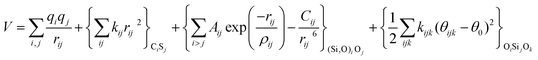
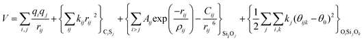
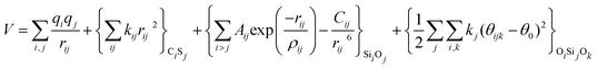
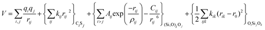
With these purposes, some FFs have been developed such as the PMM08, whose potential energy expression is presented in Table 1. But despite this aspect playing a key role in the evaluation of the properties of a material with potential use in mixture separations, in this review we only treat the accuracy of broadly used FFs to reproduce bulk properties.


Secondly, the low diffusivity in the zeolite systems, which occurs as a consequence of the close match between guest kinetic diameter and window size, makes experimental determination of diffusivities a difficult task and also challenges computational methods to make estimates in computer accessible time scales. 64 structures, out of a total of 201 framework type codes, meet the requirement of having 8-rings as the largest.3 Less than 10 pure silica 8-ring zeolites have been reported so far in separations of C3 hydrocarbons. Considering that, accounting for energetic criteria, most of the 64 structures could be (or have been) synthesised as pure silica (see Section 2 in ESI†), this means that there is considerable room for improvement of existing technologies on such types of separations. Taking into account that a large room for synthesizing new zeolites has also been reported,4 this altogether suggests that this could be an important field of research in the future.
In this regard, Molecular Dynamics (MD) is one method to study diffusion because it provides atomistic information of the dynamics of every particle of the system, which can be easily related to experimental measurements. Importantly, the fact that these separations do largely depend on the pore size of zeosils makes crucial the quality of the force fields (FFs) used in the simulations. If a FF cannot accurately reproduce structural factors, it will hardly be of use to assess how different zeosils perform in separating hydrocarbons. Secondly, apart from statical structural requirements, the flexibility of the zeosil also should be sufficiently well modelled by the FF. Zeolites, in general, are flexible materials and the pore dimensions depend on vibrational properties, which in turn depend on the temperature.26
Indeed, via MD simulations it is possible to predict properties at the atomic level of SiO2-based systems with great accuracy. However, one of the crucial challenges for the successful application of this computational approach to simulate silica compounds has been the development of accurate interatomic forcefields to reproduce the properties of those materials and this is so at least in two aspects. On the one hand, MD requires an interatomic FF which has to be sufficiently good so as to treat the framework vibrations properly, and in the field of microporous silica-based materials this is crucial because the dynamics of framework vibrations will affect the dynamic micropore size. Different studies have focused on this aspect,27 which is, nevertheless, neglected some times.
The second important issue is that diffusion and adsorption processes, whose understanding is basic for separation and catalytic applications, must be modelled appropriately and therefore the treatment of intermolecular interactions between zeolites and adsorbates ought to be of good quality.28 As this second point requires specific interest we will not treat it here, and hence we will focus only on the influence of the FF for the simulation of the framework phenomenology.
Although the field of simulation of silicon oxide materials started decades ago, it is still a very active area of research. In the case of zeolites, the initially very simple, albeit very accurate non-bonding interatomic potential of Sanders et al.,11 or the molecular mechanistic approach of Smirnov and Bougeard,25 is a good example of such success. The search for a FF able to efficiently and accurately predict structural and dynamical properties of silica-based materials started with the development of simple two-body potentials. These FFs, normally following the Born–Mayer model, were able to successfully predict relevant structural properties of silica polymorphs. The inclusion of functional ways to account for polarization effects,11 and later on, the inclusion of three-body terms,22 has allowed an improvement in the modelization of structures, as these terms play a key role in the correct representation of the Si–O interactions.
Examples of specific potentials featuring polarizability are the shell-model used by Schröder and Sauer (SS96)12 and Gale,14 as well as the variable charge approach included in the Garofalini potentials29 and the charge equilibration (QEq) scheme of Rappé and Goddard.30
Several studies focussing on the comparison of potentials for silica containing materials have been published in the past. To cite a few examples we have the studies of Herzbach et al.,31 Zwijnenburg et al.32 and Muralidharan et al.33 These authors have compared widely used potentials, like van Beest et al. (BKS)21 and Tsuneyuki et al. (TTAM),24 with new models in which a more sophisticated representation of charges or an alternative parametrization of classic potentials improves the predictions of thermomechanical, structural and dynamical properties of silicon oxides. Herzbach et al.31 compared structural, thermomechanical and dynamical properties of pure silica polymorphs calculated using the classical BKS and TTAM potentials with those extracted from potentials with a more elaborate charge representation, such as the dynamic charge equalization scheme implemented by Demiralp et al.34 and the dipole polarization from Tangney and Scandolo,35 the latter parametrized purely from ab initio data and including the Madden and Wilson dipole polarization scheme.36 More recently Zwijnenburg et al.32 compared thermochemical experimental data of three membered ring-containing siliceous materials with predictions from the SLC, BKS, Sastre and Gale (SG) force fields37 and from periodic density functional theory (DFT) calculations. Following the same line, Muralidharan et al.33 present energetic and structural properties of pure silica materials calculated with a new embedded atom (EAM) style potential. This new environment dependent dynamic charge potential has the particularity of being parametrized with energetics and structures obtained by DFT applied to small silica clusters. The potential is then compared in performance with the BKS and the TTAM potentials.
The key property of microporosity makes silica zeolites appropriate materials for applications. Crystalline microporous materials that control diffusional access through 8-ring window apertures are particularly useful for adsorptive separations of gases and small hydrocarbons.38–40 Traditional adsorptive separations are based on size-exclusion or exploit differences in the equilibrium loading of the various molecules. When the size of the windows becomes comparable to the size of the molecules, the materials can favour a kinetic differentiation in the rates of diffusion, which are an alternative to the more conventional equilibrium and size exclusion approaches. For practical purposes, the materials used in kinetic separations are required to have a large adsorption capacity of the fast diffusing components and the larger the diffusional differentiation the higher the purity that the separation can achieve.9
The potential of pure silica chabazite (CHA) and other 8-ring materials for kinetically separating propylene from propane has been described by Zhu et al.41 and Olson.42 On Si-CHA, propylene diffusivities were reported to be several orders of magnitude larger than those of propane and from this large difference in diffusion rates, it was proposed that propylene could be selectively separated from propane via a kinetic based separation scheme. Kinetic separation of CO2–CH4 has also been suggested using pure silica zeolites, with 8-ring zeolites showing the best performance.40
The fact that 8-ring pure silica zeolites owe their separation capacity to the similarity between the sizes of the 8-rings and the adsorbate molecules highlights the need of appropriate force fields that accurately reproduce the sizes and shapes of the 8-rings. In fact, this requires an accurate representation of all the structural properties of the zeolite, such as unit cell parameters, SiO bond lengths, OSiO and SiOSi angles.
It has been argued that the correct modelization of diffusion of small hydrocarbons in 8-ring zeolites needs an adequate treatment of the relevant window dimensions, but without the further need of taking into account the dynamical behaviour of the zeolite apertures as the hydrocarbons diffuse.43,44 This is true for the case of small hydrocarbons such as methane, but if the sorbate and the window apertures are of similar size, it has been shown that the sorbates deform the zeolite window as they diffuse.45,46
The intrinsic flexibility of zeolites is due to the relatively small energetic penalty associated with the change in SiOSi angles from their equilibrium value up to nearly 180°.47 Hence, when sorbates and zeolite windows are of similar size – as it is always the case in zeolite based kinetic separations – it is highly desirable to include framework flexibility in the simulations. An appropriate performance of the force field regarding flexibility requires a good quality of the potential energy surface not only at the minimum but also at nearby geometries.25,26
We now analyze the performance of a wide selection of interatomic forcefields for small pore zeolite materials. Being that quartz properties are mainly used for the FF parametrization it will also be included in our tests along with other high density silica polymorphs. Thus, a set of widely used force fields are chosen and tested by calculating structural, mechanical and dynamical properties of high density silica polymorphs (α and β quartz and coesite) and a representative selection of 8-ring pure-silica zeolites (LTA, CHA, IHW, SAS, ITW and ITE3). Energies, lattice parameters, volumes, Si–O and Si–Si lengths,  and
and  angles, static and high frequency dielectric constants are extracted from the calculations and compared with experimental values, when available.
2 Force fields for silica polymorphs
The potentials selected in this review, depicted in Table 1, can be grouped into two major sets. First, a collection of classic two and three body Born–Mayer, rigid ion type potentials, among which BKS and TTAM are possibly the most widely used. This initial list is completed by the potentials derived or parametrized by Auerbach et al. (AMCM),20 Jaramillo and Auerbach (JA),19 Vessal,22 Jackson and Catlow (JC)17 and Pedone et al. (PMM06).23 A second subgroup comprises a set of formal charge, shell model two and three body potentials. These potentials are: Sanders et al. (SLC),11 Gale,14 Sastre and Corma (SC1),15 Schröder and Sauer (SS96),12 Sierka and Sauer (SS97)13 and Pedone et al. (PMM08).16 A special group of molecular mechanics type potential is chosen as well. In this category we have the potentials by Demontis et al. (DSQFG),18 Smirnov and Bougeard (SB),25 and Sastre and Corma (SC2).15Further types of potentials featuring sophisticated ways of accounting for polarizability such as the QEq method of Rappé and Goddard,30 and Demiralp et al.34 will not be included in our test. Some other approaches, akin to those used in MD calculations, such as the adiabatic shell model of Tilocca et al.48 or the fluctuating charge models of Tangney and Scandolo,35 Olano and Rick,49 and Garofalini et al.50 are also worth mentioning for further studies. A somewhat deeper discussion of the selected potentials, regarding their functional forms and the parameters and parametrization procedures, will be given in the next section.
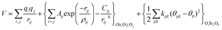
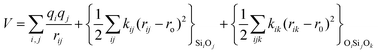
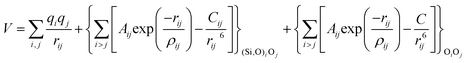
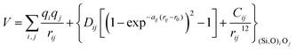
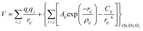
The first group of FFs selected for the present study are based on the Born–Mayer model for ionic solids, which may be separated into the following terms: a Coulombic term accounting for the long-range electrostatic interactions, a term accounting for the core–shell interactions, in the case where the shell model is incorporated, a short-range two-body function which models the repulsion and the dispersion energy between close pairs, and in some cases a three-body interaction term which is included in the potential expression to account for the extra rigidity given by the partially-covalent character of the SiO bond to the SiO4 tetrahedra. For a general view, the explicit terms included in the potential energy expression of each FF (represented in eqn (1) schematically) are presented in Table 1.
| V = VCoul. + Vcore−shell + V2-body + V3-body | (1) |
The first term in eqn (1) and in the FF expressions defines the Coulombic energy (eqn (2)), which is a sum over all point charges q, cores and shells (if the shell model is used), and dipoles (if dipole polarization is included), with rij being the separation between the point charges qi and qj. Although the Coulombic term seems to be very simple, it accounts for the major part of the potential energy in a system, and it is a mathematically challenging summation to evaluate.
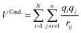 | (2) |
The difficulty in evaluating this expression is that it is conditionally convergent. However, this problem is normally circumvented by using the Ewald formalism, which divides the Coulombic interaction into two convergent series, in real and Fourier space respectively. However, the assumption of periodicity imposed for the reciprocal part of the Ewald summation is quite problematic when dealing with non-periodic systems, as well as being computationally costly, yielding a N3/2 scaling for the computational load, where N is the number of particles in the system. The particle–particle particle–mesh method is a modification of the Ewald approach, with a computational load scaling of N log(N).
A different way of evaluating the Coulombic interaction, improving remarkably the convergence behavior of eqn (2), is based on the observation that the Coulombic interaction is rather strong at a short range and quickly decreases in magnitude as the inverse of the distance between particles. Hence, by ensuring that the net charge within a cut-off sphere equals zero and applying a damping function with a damping factor that minimizes the systematic error in the calculation, the total electrostatic energy could be accurately calculated for a spherically truncated 1/r summation. This method50 has the advantage of being less costly computationally, and it is being used as an alternative to the Ewald approach.
On the other hand, it is worth mentioning that the dynamic QEq proposed by Rappé and Goddard 30 is based on a calculation of geometry dependent distribution of atomic charges from a charge equilibration electrostatic functional. The electrostatic functional reflects the effect of atomic ionization potentials, electron affinities and atomic radii on the electrostatic charge interactions between the particles in the system. The calculation of charges following this scheme shows an excellent agreement with experimental dipole moments and with charges calculated from ab initio methods.
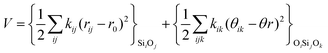
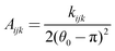
The second part of the potential energy equation (1) features a term for including polarizability of the ions in the system through the shell model (3). As a general rule only the anions are divided in the core and the shell, and thus they represent a pair of point charges, the positive one being the core and the negative the shell, both connected by a harmonic spring, with force constant k and core–shell distance given by rc−s. The addition of the shell model has the effect of improving the treatment of electrostatic interactions, improving the values of static and high frequency dielectric constants, as well as predicting more accurately dynamical properties.
| Vcore–shell = krc−s2 | (3) |
Tilocca et al.48 have recently used a potential including polarization effects via the adiabatic shell model to perform MD calculations on silica-containing materials. They found that the inclusion of polarization improves the prediction of the intratetrahedral structure for the materials studied, because the shell model allows a better description of the SiO2 intratetrahedral bonding and of the local polarization phenomena. This advantage of the shell model applied to MD can be important when simulating the diffusion of polar molecules in porous media, because it allows a better treatment of the electric perturbations caused for the guest on the ions of the framework.
The third term of eqn (1) stands for the two-body interactions which can be approached in different ways. For instance, three of the models studied, namely DSQFG, SC2 and SB (see Table 1), use a harmonic two-body function to describe the interactions between atoms. The harmonic function is basically a second order truncated Taylor expansion in terms of the interatomic distance between directly connected T–O pairs, as described in eqn (4).
 | (4) |
A formulation developed in this way allows a computationally efficient form to evaluate the forces acting in the framework, converting the host into a very efficient heat bath, which thermalizes the guest molecules through the coupling of host–guest modes. This type of potential was devised principally to study the behaviour of guest molecules inside porous materials.
On the other hand, most of the FFs described in Table 1 use the Buckingham function (eqn (5)) to account for the non-bonding short-range repulsive/dispersive interactions. In the case of potentials using the shell model, the interactions involving anions consider the coordinates of shells rather than cores. The Buckingham potential is applied to pair interactions involving oxygen, and it is customary in most force fields for SiO2 to exclude short-range forces between Si atoms. Eqn (5) is divided into two terms: a repulsive contribution, given by the exponential term, and an attractive-dispersive one. This formulation allows treatment of the forces among the atoms as physically reasonable as possible, for both, short and medium range distances.
 | (5) |
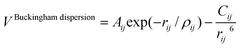
A variation of the Buckingham potential is the four-range Buckingham, which divides the range of action of the potential into four regions according to:
| V4-Buckingham = Aij exp(−rij/ρij), rij < r1 | (6) |
 | (7) |
 | (8) |
 | (9) |
This formulation was used by Vessal to study structural properties of silicate and phosphate glasses.22
The PMM potentials (PMM06 and PMM08) use a Morse function to describe the short-range ionic interactions, although this function is normally used to describe bonding in covalent systems. In the PMM potentials, the Morse function is not used to describe a meaningful physical interaction, such as dissociation energies or equilibrium bond distances, given by Dij and r0 in eqn (10) respectively. These parameters must be considered merely fitting parameters.23
| VMorse = Dij[{1 − exp(−aij(rij − r0))}2 − 1] | (10) |
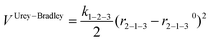
Regarding the terms to account for the three-body interactions, in Table 1 it is observed that the Urey–Bradley function is used in two of the potentials: DSQFG and Gale. This function is basically a two-body potential that is applied to a triplet, where the two terminal atoms are connected to the same central atom. Eqn (11) shows the parameters used by the Urey–Bradley function, r2−1−3 being the distance between the two terminal oxygen atoms in the  triplet, and r2−1−30 the equilibrium distance. This model is used to reduce the computational cost of three-body functions in the minimization of free energies of silicates and to study structural and dynamical properties of zeolites by MD.14
 | (11) |
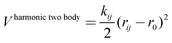
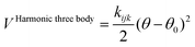
The harmonic three-body functional form is used to account explicitly for the sp3 hybridization of the covalent SiO bond. The deviation of the angle (θ) with respect to the equilibrium angle (θ0 = 109.47°, in eqn (12)) is multiplied by a constant k, which represents the stiffness of the O–Si–O triplet. Seven of the models studied (SLC, SS96, SS97, JC, SC1 and SC2) use this functional form to study from structural properties to reactivity of silica and zeolite catalysts.11–13,17
 | (12) |
Finally, the Vessal three-body function, as expressed in the following eqn (13):
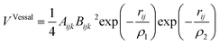 | (13) |
 | (14) |
| Bijk = (θ0 − π)2 − (θijk − π)2 | (15) |
 triplet or the
  . In the potentials AHCM20 and JA19 the Vessal function is used to model the
  , whereas in the work of Sastre and Corma (SC1, SC2)15 the
  angle is modelled by a harmonic function and the
  is represented by the Vessal expression. This function was used originally to model amorphous silica and other systems featuring a wide distribution of either
  or
or  angles.22
3 Pure silica models
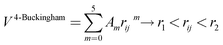
In order to test the FFs, we have selected three high density silica polymorphs: α and β-quartz and coesite. α-Quartz is the thermodynamically stable phase of quartz under normal conditions, composed of corner shared SiO4−4 tetrahedral units. It has a trigonal 9 atom unit cell with the P3121 space group symmetry. Because it has been exhaustively studied, their empirical and calculated properties represent one of the main sources of data for parametrization of interatomic potentials. β-Quartz is the high temperature phase of quartz that appears at temperatures over 847 K.51 The structure of β-quartz shows an hexagonal unit cell, composed of 9 atoms, with group symmetry P6122. Coesite is the high-pressure phase of quartz, it has an interesting structure having two nonequivalent silicate tetrahedral units, thus making it an excellent candidate to test the transferability of potentials parametrized with α-quartz data.52 Coesite features a monoclinic-beta unit cell composed of 48 atoms, with the C2/c group symmetry. Section 4 in ESI† summarizes some structural parameters of the quartz polymorphs selected for our test.On the side of low density SiO2-based structures we have selected 6 pure silica framework types, namely LTA, CHA, IHW, ITE, ITW and SAS (Fig. 1).
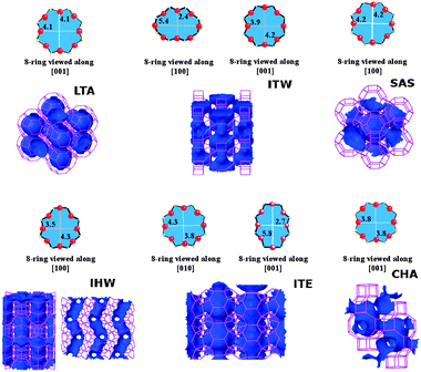 | ||
| Fig. 1 Schematic representation of the ring size and the channel system for the 8-ring pure silica zeolites with framework types LTA, ITW, SAS, IHW, ITE and SAS.3 | ||
Pure silica LTA (zeolite ITQ-29) consists of an arrangement of sodalite cages which are connected through the square faces, forming double four-ring units. It has 72 atoms in a cubic unit cell, with space group symmetry Pm3m. Zeolite ITQ-29 can be seen as a three-dimensional network of spherical cavities (alpha-cages), of about 11.4 Å in length, interconnected by six small 8-ring windows with effective diameter of 4.1–4.2 Å.3,53 All silica LTA can also be described as a structure made of sodalite cages (beta-cages) connected through the square faces with each other, forming double four-ring units. The diffusion path available in this zeolite involves the three crystallographic axes.
Pure-silica CHA has a rhombohedrical unit cell containing 36 atoms, with space group symmetry R3m and with four crystallographically distinct Si–O–Si angles.54 It is formed by rings of 8, 6 and 4 members in a 3-dimensional network of interconnected cages. The 8-ring windows present in this framework have effective diameters of ∼3.8 Å.3
The pore topology of the ITQ-32 zeolite (IHW framework type) features a unidirectional small 8-ring channel system along the crystallographic a-axis, with a pore aperture of 3.5 × 4.3 Å.3 The 8-ring pore system is perpendicularly crossed by a 12-ring width cavity, which interconnects two neighboured 8-ring channels along the c direction. These bridged 12-ring channels have a diameter of 6.3 and 16.2 Å in length.55 ITQ-32 has been the object of several experimental studies for adsorption and separation of olefins from paraffins, which highlights the potential of this structure for the kinetic separation of similar sized molecules, as is the case of propane–propene.7
The ITQ-3 zeolite (ITE framework type) is a structure formed by a bidimensional network of straight channels connected by 8-ring windows running along the b and c crystallographic axes, with space group symmetry Cmcm in an orthorhombic unit cell. The intersection of both types of channels generates four large cavities per unit cell, with two different 8-ring windows with different opening sizes56 (4.3 × 3.8 Å and 2.7 × 5.8 Å3). The marked difference in window openings in this material (see Fig. 1) only allows the diffusion of hydrocarbons along the b crystallographic axis, thus becoming a pseudo one-dimensional arrangement of interconnected cages. This zeolite has also been the object of experimental studies due to its ability to adsorb small hydrocarbons, and its potential for molecular sieving processes has been recognized by the differences in adsorption rates for propane and propene.57
Zeolite SSZ-73 is the pure silica form of the SAS framework, with one dimensional channels formed by 8, 6 and 4 ring units, and with an I4/mmm space group symmetry.58 The SAS structure is made of lta cages linked by d6r building units, which gives 8-ring channels across the [001] crystallographic direction, with 8-rings having circular shape with an effective diameter of 4.2 Å.
Zeolite ITQ-12 (ITW) contains a two dimensional system of channels accessed via 8-ring windows. It features space group symmetry C2/m, which translates as a monoclinic structure with two dimensional channels limited by 8-ring windows. Along [100], the channel limited by 8-ring windows is extremely narrow (2.4 × 5.4 Å), while the channels along [001] are more open through less elongated windows (3.9 × 4.2 Å59).
Section 4 of ESI† shows the lattice parameters and volumes of the selected zeolite structures. The chosen set of structures features a sufficiently wide pool of structures for testing the accuracy of the FFs. Also, as most of the potentials studied were parametrized with α-quartz data, it will give us a way to evaluate the ability of the potentials to predict the properties of compounds out of the parameter fitting data base.
4 Results and discussion
We have calculated structural, mechanical and dielectric properties of all the silica polymorphs, using the GULP60 software. In all cases the experimental X-ray resolved unit cells have been used as initial models. The optimization of the structures is achieved through an energy minimization process at constant pressure, including all the simulation cell variables. The program ZeoTSites61 was used to analyze the connectivity and some structural properties (such as bond distances and angles) of the calculated structures. A complete set of tables showing the calculated data is provided in ESI.†For the structural properties, we have calculated the lattice parameters (a, b, c/α, β, γ) and the bond distances Si–O and Si–Si, as well as the angles between  and
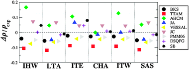
and  triplets. These properties provide a good indication of the ability of the different FFs to reproduce the structural properties reported experimentally. Fig. 2 represents the relative errors obtained, after the lattice minimization performed with the FFs listed in Table 1, for the structural properties of the both high density silica polymorphs and the zeolite frameworks selected for the study. As mentioned, these error values were computed taking as reference the experimental value when available (see the complete set of results in ESI†, Section 5). However, in those cases where the experimental data were not available, the value reported in the IZA database3 for the corresponding framework was taken as reference.
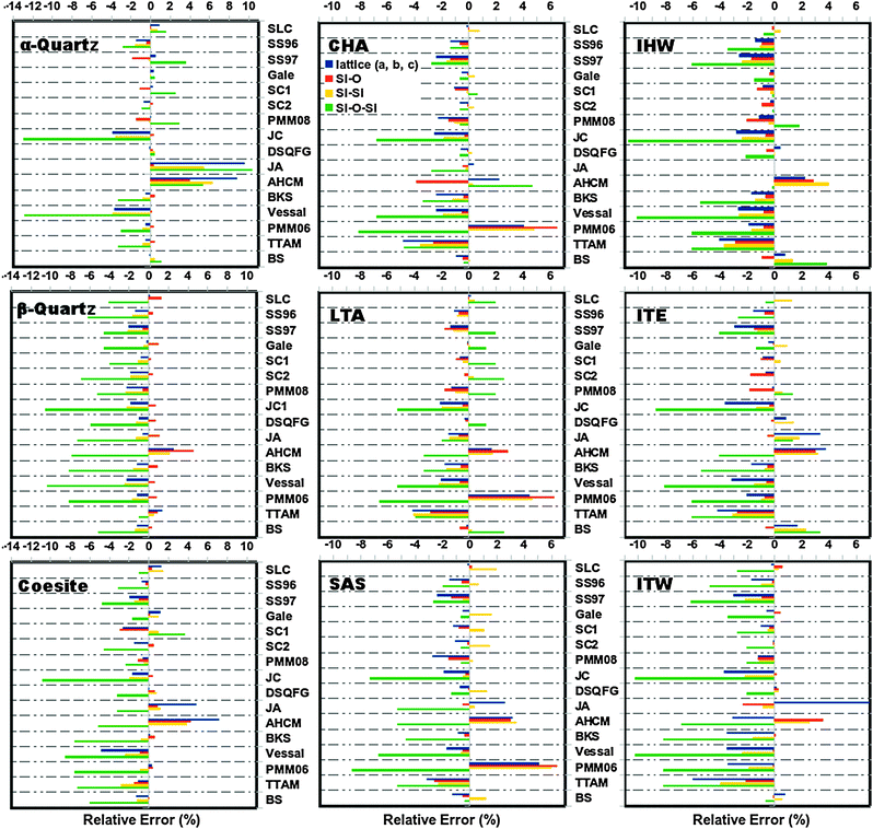 | ||
| Fig. 2 Relative error (%) computed for the structural parameters of the pure silica polymorphs, α-quartz, β-quartz, coesite and zeolites CHA, LTA, SAS, IHW, ITE and ITW, calculated with the selected FFs (this figure is intended to show only a visual overview of the several performance of the selected FFs in reproducing structural features. For a more detailed inspection, individual tables are provided in ESI† (Section 8)). | ||
The lattice parameter selected for comparison corresponded to the a, b, or c parameter with the highest values of relative error. For all the structures, the unit cell angles (α, β and γ) were in excellent agreement with the experimental values where the relative errors are below 0.8%. On the other hand, as observed in Fig. 2, the largest errors were obtained for the Si–O–Si angle, with maximum values of ∼13 and 11% for the high density polymorphs and zeolite frameworks respectively. These particular errors were observed for α-quartz and IHW optimized with the JC force field. Conversely, all the FFs reproduce the O–Si–O angles successfully, with error values below 0.2%.
In general, the best structural properties are predicted by the core–shell model force fields, with the SLC giving good and Gale giving excellent results. Within the rigid ion force fields and with exception of the JA and AHCM, which yield the highest values of errors, all the FFs perform equally well for the high density polymorphs with errors below 5% in the cell parameters and Si–O distances. Particularly BKS, PMM06 and TTAM presented the lowest error values for these parameters. On the other hand, in the case of the low density silica polymorphs the best structural parameters are predicted by the BKS while the other FFs deviate similarly from the reference values.
Regarding the molecular mechanics FFs (SC2, DSQFG and SB), it was observed that these FFs reproduce with good quality both types of structures (high and low density silica polymorphs) yielding in most of the cases the lowest deviations of the structural parameters compared.
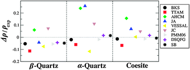
Fig. 3 compares the density, calculated with rigid ion FFs, with experimental values for the three high density polymorphs of silica. From the figure it is readily obvious that the best rigid ion FFs in reproducing the experimental density are the BKS and PMM06 models – although slightly and consistently underestimating the experimental values – and the molecular mechanics FFs SB and DSQFG.
 | ||
| Fig. 3 Calculated and experimental density, for high density polymorphs of silica, calculated using rigid ion FF. | ||
On the other hand, the values obtained with the AHCM and JA models for α-quartz are way off, and are consistently overestimated, except for β-quartz where JA underestimates the experimental value. In this regard, JA and AHCM FFs calculate an average  angle for α-quartz which is too small (129° and 136° respectively) compared with the experimental value (144°, see Fig. 2).
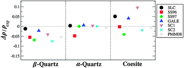
For calculated values of densities obtained through the shell model-FFs, which are depicted in Fig. 4, we observed an excellent agreement with α-quartz experimental values in most of the FFs, with the exception of SS96. It is also interesting to see that although the SS96 does not correctly reproduce the α-quartz density, it does a great job reproducing the density of coesite, being the only FF correctly reproducing the experimental value. All of the FFs tend to underestimate the density of β-quartz, with more accuracy obtained for SLC and Gale. SC1, SLC and Gale predict higher values for coesite density, whereas the other FFs give underestimated values.
 | ||
| Fig. 4 Calculated and experimental density, for high density polymorphs of silica, calculated using shell model FFs. | ||
Predictions of bulk modulus and elastic constants for α-quartz are shown in ESI† (Section 5). For α-quartz, all of the FF calculated values are in good agreement with experimental values, except for JC and Vessal values, which produce values way too high, 122.11 and 199.16 Gpa, respectively, compared with the experimental bulk modulus of 38.98 GPa. For β-quartz a good comparison of results is not possible, because the experimental values are obtained at the α−β transition temperature whereas our results are calculated under zero temperature and pressure conditions.
Static and high dielectric constants for α-quartz are given in ESI† (Section 6, Table S15). Calculated values for the static dielectric constants (ε110 − ε330) using rigid ion FFs differ from the experimental values, because of the rigid ionic approximation. The experimental values (ε110 = 4.51, ε330 = 4.60) are in general well reproduced by the shell model FFs, with the best agreement for the SS97 and SLC models with values of ε110 = 4.47, ε330 = 4.65 and ε110 = 4.58, ε330 = 4.88, respectively.
Calculated densities of the low density pure silica structures are depicted in Fig. 5 and 6 for rigid ion and shell model FFs respectively. Rigid ion FFs reproduce somewhat accurately the density of these structures, AHCM being the FF which consistently overestimates the experimental values. In the case of zeolite SSZ-73, PMM06 calculates an average Si–O distance of 1.499 Å, while the experimental Si–O distance is of 1.602 Å, being, along with AHCM, the only models which produce low values for the Si–O distance for all low density structures. JC, JA, BKS and Vessal FFs consistently predict low values for the density of the zeolite structures, JA being the one which renders a better value for Si-CHA. In general, the densities of the low density polymorphs (Fig. 5) are well predicted by the BKS and PMM06 FFs, which underestimate the density, although the trends are reproduced correctly.
 | ||
| Fig. 5 Calculated and experimental density, for low density polymorphs of silica, calculated using rigid ion FFs. | ||
 | ||
| Fig. 6 Calculated and experimental density, for low density polymorphs of silica, calculated using shell model FFs. | ||
Less accurate predictions are performed by Vessal and JC FFs, which underestimate and overestimate, respectively, the densities, with the best predictions obtained with the molecular mechanics FFs DSQFG and SB, with the exception of the density of ITE, which is overestimated by both potentials.
The shell model-FFs produce, in general, better approximations to experimental values of densities compared with the predictions of rigid ion FFs. SLC, Gale and SC1 FFs are the most accurate in predicting these values, while SS97 is the FF which reproduces the experimental values with lower accuracy. A complete discussion about the prediction of stability and structures of silica polymorphs using the rigid ion model and shell models is given by de Boer et al.,62 where they showed that predictions done with shell model-FFs are closer to experimental values for a set of high density silica polymorphs and zeolite structures.
However, for applications dealing with MD, such as diffusion of hydrocarbons in zeolites, the use of a shell model potential requires an order of magnitude slower computations due to the high frequency of the core–shell vibrations which force to reduce the timesteps accordingly.63 Hence it is computationally convenient to select rigid ion force fields for such applications.
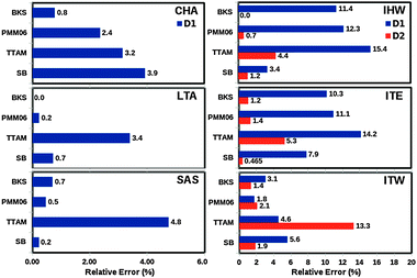
Having found that BKS, PMM06, TTAM and SB are good (rigid ion) forcefields to simulate structural properties of pure silica zeolites, a further structural test will be considered. An additional qualitative view of the performance of these FFs can be obtained by comparison of the pore volumes computed for the minimized structures and the experimental reports. These values show a reasonable agreement with the experimental results (see ESI†, sSection 9). However, depending on the approximation employed to estimate the free volume, approached usually as the volume occupied by spheres with molecular or atomic diameters (nitrogen or argon respectively), special care must be taken in such a comparison.
Previous properties, such as unit cell parameters, SiO bond lengths, etc., can be obtained from ‘static’ calculations, in which no explicit account is taken of thermal motions. Such calculations are usually based on an energy minimization procedure involving relaxation of the coordinates of lattice ions. However, temperature affects the pore dimensions by activating vibrational motions which produce a periodically dynamical pore size fluctuation. Also temperature influences the cell volume, with zeolites frequently showing negative thermal expansion.64 When sorbates are of similar size to micropores, neglection of the thermal effects may lead to wrong conclusions regarding transport properties.
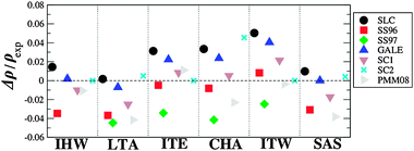
We have estimated the 8-ring window apertures of the six pure silica zeolites considered in this study (IHW, LTA, ITE, ITW, SAS and CHA), by computing the radial distribution function of the O⋯O interatomic distances, between the oxygen atoms which determine the ring openings (see Section 7 in ESI†), via NVE MD calculation at 300 K. These simulations were performed with 5.5 × 10⁵ steps and a time step of 1 fs, employing the velocity verlet scheme for the integration of the motion equations. For each simulation, the frameworks – previously optimized with each FF – were used as starting configurations. After 5 × 10⁴ steps of equilibration, trajectories of 1 × 10⁴ steps were captured to analyze the material properties.
Apart from the average 8-ring apertures obtained by each force field, we also report the standard deviation of the Gaussian function of the window diameters obtained at each step of the MD simulation (see Section 7 in ESI†). The quality of the estimations of these apertures was measured by comparing the average value obtained from the simulation and the values reported in the Atlas of Zeolite Framework Types3 (see Fig. 1). The computed standard deviations, around 0.35 Å, show the fluctuation of the 8-ring diameters due to the thermal vibrations and the zeolite flexibility. The relative errors in the window diameters are shown in Fig. 7.
 | ||
| Fig. 7 Relative errors in the window diameters for the pure silica zeolites (CHA, LTA, SAS, IHW, ITW, ITE as indicated, see Fig. 1), computed as the radial distribution function of the O–O inter-atomic distances obtained along the MD simulations performed at 300 K, within the NVE ensemble (see Section 7 in ESI†). | ||
Clearly TTAM is the worst performing, with relative errors above 13% (>0.5 Å) in three zeolites (IHW, ITE and ITW). BKS and PMM06 perform nearly equally well with maximum relative errors consistently below 12% (<0.4 Å). On the other hand, the molecular mechanics SB yielded the smallest errors, within 8%. The average errors in 8-rings window apertures using SB, BKS and PMM06 are 0.11, 0.12 and 0.14 Å respectively. The IZA values range between 3.6 and 4.3 Å. We believe that the use of BKS, SB and PMM06 guarantees a good accuracy to simulate transport properties of tight fitting sorbates in 8-ring zeolites.
Increasing the temperature does not affect the average pore diameter but increases the standard deviation and makes the windows breath with larger amplitude. This has been recently shown for CHA and SAS.65 Amplitude increments are about 0.1 Å between 300–800 K, and so this effect is not very pronounced. So, what happens when such fitting adsorbates do actually cross an 8-ring? 8-rings dynamically adapt their size to allow adsorbate passage. This is a second reason why correct pore dimensions are crucial and framework dynamics do improve the quality of the simulation.
Without this dynamic effect, using the correct geometry for all the zeolite atoms at the given temperature and keeping the framework rigid would be enough to guarantee accurately simulated transport properties. This is in fact a good strategy for adsorbates clearly smaller than the window size.44 However, kinetic separations can only be performed when the zeolite pore is about the same size as the adsorbates, and in these cases only a dynamic consideration of the pore size allows an accurate representation of the transition state barriers posed by the adsorbate crossing the zeolite 8-ring.
To show this, we have extracted snapshots corresponding to 8-ring crossing by propane and propylene in pure silica CHA. The molecular dynamics have been performed within the NVE ensemble at 600 K. More details can be found in the original publication.65 In the six snapshots included in Fig. 8 and 9 the dimensions of the 8-ring change notably and only when the 8-ring becomes sufficiently large can propane diffuse through, and the same occurs with propylene. Which pore size should then be used in a fixed framework simulation? Fixed framework simulations with the two extreme 8-ring sizes would give different diffusivities. Crossing the 8-ring requires an event with two conditions: (i) not only appropriate velocity and location of the hydrocarbon, but also (ii) a simultaneous appropriate window opening. Events meeting the condition (i) but not (ii) would be regarded as successful 8-ring crossing in a fixed framework simulation using the largest pore size, but they would be unsuccessful if using the lowest pore size. The fact that the largest (but not the smallest) 8-ring size in pure silica CHA allows the passage of propane precludes a correct simulation of transport without a flexible framework. In the case of propylene both 8-ring sizes might possibly allow the passage but the values of the activation energies will be highly dependent on the crossing rate, and, again, only a flexible framework simulation is able to capture the adequate balance.
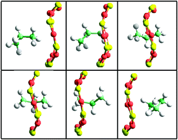 | ||
| Fig. 8 Snapshots taken from a flexible framework molecular dynamics NVE simulation at 600 K in a pure silica CHA (288 SiO2) containing 4 propane molecules. The dimensions of the 8-ring are (from left to right and top to bottom): 3.84 × 4.00 Å, 4.01 × 3.72 Å, 3.87 × 4.26 Å, 4.11 × 4.12 Å, 3.58 × 4.05 Å, 3.70 × 3.88. The activation energy calculated from these configurations is 6.8 kcal mol−1. The time difference between each frame is 0.2 ps. | ||
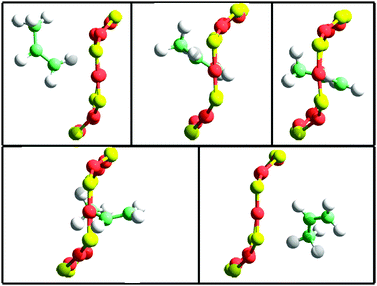 | ||
| Fig. 9 Snapshots taken from a flexible framework molecular dynamics NVE simulation at 600 K in a pure silica CHA (288 SiO2) containing 4 propylene molecules. The dimensions of the 8-ring are (from left to right and top to bottom): 4.04 × 3.71 Å, 3.72 × 4.033 Å, 3.45 × 4.57 Å, 3.42 × 4.67 Å, 4.05 × 4.04 Å. The activation energy calculated from these configurations is 1.4 kcal mol−1. The time difference between each frame is 0.2 ps. | ||
For the diffusivity of these hydrocarbons in CHA it is interesting to consider the time scales of the different motions (pore breathing and hydrocarbon diffusion) and taking into account that the subsequent frames displayed in Fig. 9 differ by 0.2 ps. During the time-span of the 8-ring window crossing, the distance travelled by the centre of mass of the hydrocarbon molecule, divided by the time employed has been calculated to be 6 Å ps−1 (propane) and 7 Å ps−1 (propylene). During the time of 8-ring crossing, the breathing pore dimensions indicated in Fig. 9 show that they do not remain constant and hence using a rigid framework should give a different result.
Therefore, the accurate characterization of adsorbate diffusivities into zeolite frameworks, via MD simulations, requires an appropriate FF to capture accurately enough both the dynamical effects of the framework (bond distances, angles and window openings) and the structure of the adsorbate molecules, and the host–guest interactions. FFs for host–guest interactions have not been reviewed in this manuscript and hence we cannot say how critical they are in the computation of the guest diffusivity. In the referred case (diffusion of propane–proylene in CHA), the details of the employed host–guest FF can be found in the previous study of our group.65 There, we used a 6–12 Lennard-Jones plus electrostatic FF for the zeolite–hydrocarbon interactions. This host–guest FF dates back to a previous study,66 which we have extensively used further on and have found particularly well suited because of its accuracy and transferability. Hence, the choice of the FF must be done by taking into account the performance of the FF to reproduce the mentioned framework properties, evaluated by comparing with experimental results in the best of the cases, and the efficiency of the codes to perform simulations as long as required to capture the physical phenomena of interest. In this regard, the information supplied in this review can help to identify the applicability of FFs in MD simulations.
5 Conclusions
The modeling of dynamical and structural properties of SiO2-containing materials, especially nanoporous polymorphs, has recently been given a good deal of attention because of the importance of these materials in a wide variety of industrial applications. MD, lattice dynamics and other methods are used to shed light on the microscopic phenomenology of processes occurring inside these materials. However, these methods rely on FFs developed to model interatomic interactions.Sometimes specific studies such as atomistic MD have to face a balanced requirement of FF features. For instance, a dilemma between using a ‘formal charges’ versus a ‘partial charges’ zeolite FF may appear. Whilst partial charges will perhaps model more accurately the electrostatics of the diffusion process itself, they may not be as accurate in reproducing structural and mechanical properties of flexible materials such as zeolites. The present review offers a sufficiently wide choice of silica FFs to select from for the specific needs of each task, by comparing and analyzing the particular features of each, based on a tabulation of different physico-chemical properties obtained through our testing.
Several FFs have been benchmarked in their ability to simulate C3 hydrocarbon separation in 8-ring zeolites, where computational efficiency suggests the use of a rigid ion FF provided accurate structure and dynamics can be obtained. SB, BKS and PMM06 FFs gave relative errors in SiO distances and cell parameters below 3%, and more importantly, average errors in the size of 8-rings of 0.11, 0.12 and 0.14 Å respectively. Results also indicate variation of pore size not lower than 0.3 Å, increasing with temperature, and finally a dynamic adaptation of the 8-ring size to the incoming C3 hydrocarbon was shown, which affects the activation energy.
We have attempted to describe the most relevant characteristics of a selected set of FFs, testing their accuracy and transferability in calculating structural, mechanical and dynamical properties of a pool of diverse structures. Some trends can be extracted from the data obtained, such as the tendency of FFs including explicit polarizability terms to predict with more accuracy structural properties. These general trends could be used as a guide to evaluate the ability of a specific FF for tackling a specific task.
Acknowledgements
We thank Ministerio de Ciencia e Innovacion of Spain for funding through project MAT2007-64682 and to the centre of supercomputing of Galicia, CESGA.References
- B. Smit and T. L. M. Maesen, Chem. Rev., 2008, 108, 4125–4184 CrossRef CAS.
- P. Caullet, J.-L. Paillaud, A. Simon-Masseron, M. Soulard and J. Patarin, C. R. Chim., 2005, 8, 245–266 CrossRef CAS.
- C. Baerlocher, L. B. McCusker and D. H. Olson, Atlas of Zeolite Framework Types, Elsevier, 6th revised edn, 2007. Also in http://www.iza-structure.org/ Search PubMed.
- O. Delgado-Friedrichs, A. Dress and D. Huson, Nature, 1999, 400, 644–647 CrossRef.
- D. S. Coombs, A. Alberti, T. Armbruster, G. Artioli, C. Colella, E. Galli, J. Grice, F. Liebau, J. A. Mandarino, H. Minato, E. H. Nickel, E. Passaglia, D. R. Peacor, S. Quartieri, R. Rinaldi, M. Ross, R. A. Sheppard, E. Tillmanns and G. Vezzalini, Can. Mineral., 1997, 35, 1571–1606 CAS.
- J. Kärger and D. M. Ruthven, Diffusion in Zeolites and Other Microporous Solids, John Wiley and Sons, 1992 Search PubMed.
- M. Palomino, A. Cantin, A. Corma, S. Leiva, F. Rey and S. Valencia, Chem. Commun., 2007, 1233–1235 RSC.
- R. Krishna and J. M. van Baten, Chem. Eng. Technol., 2006, 29, 1429 CrossRef CAS.
- N. Hedin, G. J. De Martin, W. J. Roth, K. G. Strohmaier and S. C. Reyes, Microporous Mesoporous Mater., 2008, 109, 327–334 CrossRef CAS.
- K. Na, M. Choi and R. Ryoo, Microporous Mesoporous Mater., 2012 DOI:10.1016/j.micromeso.2012.03.054.
- M. J. Sanders, M. Leslie and C. R. A. Catlow, J. Chem. Soc., Chem. Commun., 1984, 1271–1273 RSC.
- K. P. Schröder and J. Sauer, J. Phys. Chem., 1996, 100, 11043–11049 CrossRef.
- M. Sierka and J. Sauer, Faraday Discuss., 1997, 106, 41–62 RSC.
- J. D. Gale, J. Phys. Chem. B, 1998, 102, 5423–5431 CrossRef CAS.
- G. Sastre and A. Corma, J. Phys. Chem. B, 2006, 110, 17949–17959 CrossRef CAS.
- A. Pedone, G. Malavasi, M. C. Menziani, U. Segre, F. Musso, M. Corno, B. Civarelli and P. Ugliengo, Chem. Mater., 2008, 20, 2522 CrossRef CAS.
- R. A. Jackson and C. R. A. Catlow, Mol. Simul., 1988, 1, 207–224 CrossRef.
- P. Demontis, G. B. Suffritti, A. Alberti, S. Quartieri, E. S. Fois and A. Gamba, Gazz. Chim. Ital., 1986, 116, 459–466 CAS.
- E. Jaramillo and S. M. Auerbach, J. Phys. Chem. B, 1999, 103, 9589–9594 CrossRef CAS.
- S. M. Auerbach, N. J. Henson, A. K. Cheetham and H. I. Metiu, J. Phys. Chem., 1995, 99, 10600–10608 CrossRef CAS.
- B. W. H. van Beest, G. J. Kramer and R. A. van Santen, Phys. Rev. Lett., 1990, 64, 1955–1958 CrossRef CAS.
- B. Vessal, J. Non-Cryst. Solids, 1994, 177, 103–124 CrossRef CAS.
- A. Pedone, G. Malavasi, M. C. Menziani, A. N. Cormack and U. Segre, J. Phys. Chem. B, 2006, 110, 11780–11795 CrossRef CAS.
- S. Tsuneyuki, M. Tsukada, H. Aoki and Y. Matsui, Phys. Rev. Lett., 1988, 61, 869–872 CrossRef CAS.
- K. S. Smirnov and D. Bougeard, J. Raman Spectrosc., 1993, 24, 255 CrossRef CAS.
- M. W. Deem, J. M. Newsam and J. A. Creighton, J. Am. Chem. Soc., 1992, 114, 7198–7207 CrossRef CAS.
- S. Jakobtorweihen, C. P. Lowe, F. J. Keil and B. Smit, J. Chem. Phys., 2007, 127, 024904 CrossRef CAS.
- R. Krishna, Chem. Soc. Rev., 2012, 41, 3099–3118 RSC.
- Y. Ma and S. H. Garofalini, J. Chem. Phys., 2006, 124, 234102 CrossRef.
- A. K. Rappé and W. A. Goddard III., J. Phys. Chem., 1991, 95, 3358–3363 CrossRef.
- D. Herzbach, K. Binder and M. H. Müser, J. Chem. Phys., 2005, 123, 124711 CrossRef.
- M. A. Zwijnenburg, F. Cora and R. G. Bell, J. Phys. Chem. B, 2007, 111, 6156–6160 CrossRef CAS.
- K. Muralidharan, C. Cao, Y.-X. Wan, K. Runge and H.-P. Cheng, Chem. Phys. Lett., 2007, 437, 92–98 CrossRef CAS.
- E. Demiralp, T. Cagin and W. A. Goddard III., Phys. Rev. Lett., 1999, 82, 1708–1711 CrossRef CAS.
- P. Tangney and S. Scandolo, J. Chem. Phys., 2002, 117, 8898–8904 CrossRef CAS.
- P. A. Madden and M. Wilson, Chem. Soc. Rev., 1996, 35, 339–350 RSC.
- G. Sastre and J. D. Gale, Chem. Mater., 2003, 15, 1788 CrossRef.
- S. E. Jee and D. S. Sholl, J. Am. Chem. Soc., 2009, 131, 7896–7904 CrossRef CAS.
- K. Li, D. H. Olson, J. Seidel, T. J. Emge, H. Gong, H. Zeng and J. Li, J. Am. Chem. Soc., 2009, 131, 10368–10369 CrossRef CAS.
- R. Krishna and J. M. van Baten, Chem.–Eng. J., 2007, 133, 121–131 CrossRef CAS.
- W. Zhu, F. Kapteijn and J. A. Moulijn, Chem. Commun., 1999, 2453–2454 RSC.
- D. H. Olson, Patent, US 6488741, 2002 Search PubMed.
- A. García-Sánchez, D. Dubbeldam and S. Calero, J. Phys. Chem. C, 2010, 114, 15068–15074 Search PubMed.
- R. Krishna and J. M. van Baten, J. Phys. Chem. C, 2010, 114, 18017–18021 CAS.
- D. I. Kopelevich and H.-C. Chang, J. Chem. Phys., 2001, 115, 9519–9527 CrossRef CAS.
- W. C. Conner, R. Vincent, P. Man and J. Fraissard, Catal. Lett., 1990, 4, 75–83 CrossRef CAS.
- G. Sastre and A. Corma, J. Phys. Chem. C, 2010, 114, 1667–1673 CAS.
- A. Tilocca, N. H. d. Leeuw and A. N. Cormack, Phys. Rev. B: Condens. Matter Mater. Phys., 2006, 74, 104209 CrossRef.
- L. R. Olano and S. W. Rick, J. Comput. Chem., 2005, 26, 699–707 CrossRef CAS.
- Y. Ma and S. H. Garofalini, Mol. Simul., 2005, 31, 739 CrossRef CAS.
- J. P. Bachheimer, J. Phys. Lett., 1980, 41, 559–561 CrossRef CAS.
- G. Dolino, Phase Transitions, 1990, 21, 59–72 CrossRef CAS.
- A. Corma, F. Rey, J. Rius, M. J. Sabater and S. Valencia, Nature, 2004, 431, 287–290 CrossRef CAS.
- M. A. Camblor, A. Corma, M. J. Diaz-Cabañas and C. Baerlocher, J. Phys. Chem. B, 1998, 102, 44–51 CrossRef CAS.
- A. Cantín, A. Corma, S. Leiva, F. Rey, J. Rius and S. Valencia, J. Am. Chem. Soc., 2005, 127, 11560–11561 CrossRef.
- M. A. Camblor, A. Corma, P. Lightfoot, L. A. Villaescusa and P. Wright, Angew. Chem., Int. Ed. Engl., 1997, 36, 2659–2661 CrossRef CAS.
- D. H. Olson, M. A. Camblor, L. A. Villaescusa and G. H. Kuehl, Microporous Mesoporous Mater., 2004, 67, 27–33 CrossRef CAS.
- D. S. Wragg, R. Morris, A. W. Burton, S. I. Zones, K. Ong and G. Lee, Chem. Mater., 2007, 19, 3924–3932 CrossRef CAS.
- P. A. Barrett, T. Boix, M. Puche, D. H. Olson, E. Jordan, H. Koller and M. A. Camblor, Chem. Commun., 2003, 2114–2115 RSC.
- J. D. Gale and A. L. Rohl, Mol. Simul., 2003, 29, 291–341 CrossRef CAS.
- J. Gale and G. Sastre, Microporous Mesoporous Mater., 2001, 43, 27 CrossRef.
- K. de Boer, A. P. J. Jansen and R. A. van Santen, Phys. Rev. B: Condens. Matter Mater. Phys., 1995, 52, 12579–12590 CrossRef CAS.
- L. Whitmore, B. Slater and C. R. A. Catlow, Phys. Chem. Chem. Phys., 2000, 2, 5354–5356 RSC.
- P. Tschaufeser and S. C. Parker, J. Phys. Chem., 1995, 99, 10609–10615 CrossRef CAS.
- A. F. Combariza, G. Sastre and A. Corma, J. Phys. Chem. C, 2009, 113, 11246–11253 CAS.
- C. R. A. Catlow, C. M. Freeman, B. Vessal, S. M. Tomlinson and M. Leslie, J. Chem. Soc., Faraday Trans., 1991, 87, 1947–1950 RSC.
Footnote |
| † Electronic supplementary information (ESI) available: List of 8-ring zeolites, force field parameters, experimental and computed physical properties of the quartz polymorphs and the zeolite frameworks employed in the study. See DOI: 10.1039/c2cs35243e |
| This journal is © The Royal Society of Chemistry 2013 |