Cation vacancy order in the K0.8+xFe1.6−ySe2 system: Five-fold cell expansion accommodates 20% tetrahedral vacancies†
J.
Bacsa
a,
A. Y.
Ganin
a,
Y.
Takabayashi
b,
K. E.
Christensen
c,
K.
Prassides
b,
M. J.
Rosseinsky
a and
J. B.
Claridge
*a
aDepartment of Chemistry, University of Liverpool, Liverpool, L69 7ZD, UK. E-mail: claridge@liv.ac.uk
bDepartment of Chemistry, Durham University, Durham, DH1 3LE, UK
cDiamond Light Source, Harwell Science and Innovation Campus, OX11 0DE, UK
First published on 18th March 2011
Abstract
Ordering of the tetrahedral site vacancies in two crystals of refined compositions K0.93(1)Fe1.52(1)Se2 and K0.862(3)Fe1.563(4)Se2 produces a fivefold expansion of the parent ThCr2Si2 unit cell in the ab plane which can accommodate 20% vacancies on a single site within the square FeSe layer. The iron charge state is maintained close to +2 by coupling of the level of alkali metal and iron vacancies, producing a potential doping mechanism which can operate at both average and local structure levels.
Introduction
The mechanisms of charge carrier density control in the iron pnictide and chalcogenide superconductors1,2 are important as small changes in composition produce metal-insulator transitions and generate superconductivity at temperatures of up to 37 K in chalcogenides3,4 and 55 K in pnictides.5,6 All of the reported materials are based on a square FeX (X = Se, As) layer built from edge-sharing of FeX4 tetrahedra. The negative charge on the layers in the pnictide case requires the presence of charge compensating cations (LiFeAs) or cation-oxide slabs (LaOFeAs). The recent demonstration that insertion of alkali metal cations between FeSe layers affords superconductivity in AxFe2−ySe2 (A = K, Rb, Cs, Tl: reported compositions for 0.7 < x < 1, 0 < y < 0.5)7–9 materials places the defect chemistry in sharp relief, as attaining an iron charge state close to +2 found in the other Fe-based superconducting families will require the creation of considerable defect concentrations on both iron and alkali metal sites. Such densities suggest defect assimilation or elimination mechanisms will be required with the originally stoichiometric FeSe layers, and these may be reflected locally in other related superconducting families where lower defect densities are needed to tune electronic properties. The crystal structures of the AxFe2−ySe2 (A = K, Rb, Cs) systems have been invariably described as the tetragonal ThCr2Si2 structure (space groupI4/mmm, with the same square FeSe lattice as in FeSe itself where a = b ≈ 3.9 Å) with a random distribution of alkali metal and/or iron defects. Vacancy ordering of the Fe cations was proposed to lead to a 5 × 5 × 1 superstructure,10 with a range of modulation vectors observed by TEM and associated with defect ordering.11 Here we present the crystal structure of two closely compositionally related members of this family as determined by single crystal X-ray diffraction.Results and discussion
In an Ar-filled glove box, 15.4 mg (0.394 mmol) of K metal (Aldrich, 99.95%) was mixed in an alumina crucible with 106.2 mg (0.788 mmol) of FeSe, which was synthesized following the procedure described in.12 The crucible was loaded into a 12-mm silica ampoule, which was sealed under reduced Ar atmosphere (ca. 500 Torr). The ampoule was heated from ambient temperature to 1030 °C at 1 °C min−1, and after 2 h of reaction time was cooled at 4 °C min−1 to 700 °C. The furnace was then switched off and the ampoule was allowed to cool naturally to ambient temperature. No visual evidence for ageing of the silica ampoule due to reaction with the alkali metal could be observed. The ampoule was opened in the glove box to reveal a product consisting of fine shiny platelets. Magnetic measurements with a SQUID magnetometer at an applied field of 20 G on the bulk samples (3.4 mg) and single crystals (mounted using silicone grease on a PTFE plate on a Teflon rod) from this batch showed they were non-superconducting. The crystals were not exposed to air at any point.Single crystal diffraction data were collected at 100 K on a Rigaku MicroMax-007HF rotating anode source (crystal 1) with Mo radiation and at 90 K on beamline I19 (crystal 2) at the Diamond Light Source using the Rigaku CrystalLogic Kappa goniometer at the zirconium absorption edge (λ = 0.6889 Å). Both diffractometers used the Saturn 724+ detector. Crystals were transferred into either Fomblin-Y or Paratone-N oil and cut to size prior to mounting on MiTeGen loops. At I19, screening images on crystal 2 (0.05 × 0.05 × 0.03 mm3) were collected with a scan width of 1 degree 5 degrees apart. The rectangular crystals had two sides of almost equal length and were smaller in the third direction. The crystals displayed a tetragonal diffraction pattern similar to the ThCr2Si2 parent. Detailed examination of reconstructed precession images of the hk0 layer (Fig. 1a) shows strong diffraction maxima due to the small sub-cell and additional weak peaks forming distinctive groups of eight reflections around the allowed peaks. The modulation is commensurate with q1 = (3/5a* + 1/5b*) and q2 = (−1/5a* + 3/5b*),11 where a* and b* refer to the I4/mmm subcell. The superstructure is commensurate, though as will be discussed later it does not have to be, depending on the precise iron vacancy level. The observed diffraction pattern can be accounted for as a twofold twinning about the original mirror planes perpendicular to the four fold axis of the sub-cell (dotted lines in Fig. 1(a)) of a body centered a + 2b, −2a + b, ccell which is a√5 × √5 × 1 expansion of the ThCr2Si2 cell. Elongation of reflections is observed along the interlayer direction c*(Fig. 1(b)). Based on the single crystal diffraction alone it is also possible to index the diffraction pattern in terms of an untwined structure with 3 modulation vectors with q1 = (3/5a* + 1/5b*), q2 = (−1/5a* + 3/5b*) and q3 = (1/5a* + 3/5b*) or a single modulation vector q1 = (3/5a* + 1/5b*) implying monoclinic symmetry and four twin domains. The former, which would produce a 5 × 5 × 1 supercell in the commensurate approximation, was discounted due to the absence of second order q1 + q3, q2 + q3 modulation peaks and the observation of single domain electron diffraction patterns requiring fewer than three modulation vectors by Wang et al.11
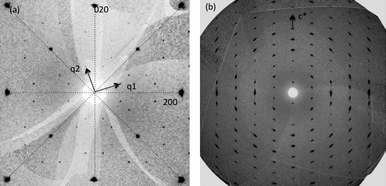 | ||
| Fig. 1 Reconstructed precession photographs for crystal 2 in the (a) hk0 and (b) h0l layers. (a) shows the two modulation vectors required to describe the cell and the sub-cell twin planes that relate the two twin components are shown as dotted lines. | ||
Systematic absences of the individual domains are consistent with space groupI4/m or I112/m. The data for crystal 2 were integrated on the 5a × 5b × ccell which indexes all the peaks for the twin domains and an empirical absorption correction based on redundancy was performed by abspack within the CrysAlis software suite. Attempts to treat the data as a twin directly in either a supercell or modulated description were either not possible or yielded unphysical results, in the limit where the two/four domains are due to micro twinning the results would be identical. The compositions obtained below using this absorption correction are also within the composition range observed by EDX in a Jeol 2000FX TEM suggesting together with the prevalence of twinned electron diffraction patterns observed that this is a valid assumption. This reflection file was then decomposed using Jana200613 into a final reflection file for the two twin domains. Data on crystal 1 (0.12 × 0.13 × 0.05 mm3) from the same batch were collected on the Rigaku rotating anode source and processed in an analogous manner using an analytical face-indexing absorption correction. Both crystal structures were solved using SUPERFLIP14 and subsequently refined using Jana2006. Solutions in I112/m were indistinguishable from those in I4/m and only the latter will be discussed. Crystal 2 (I19 diffractometer) refined to give R1(obs) = 5.7%, Rw(all) = 9.4% whilst crystal 1 (Rigaku diffractometer) refined to R1(obs) = 5.8%, Rw(all) = 8.5%. The refined compositions were K0.93(1)Fe1.52(1)Se2 (crystal 1) and K0.862(3)Fe1.563(4)Se2 (crystal 2) corresponding to formal iron charge states of 2.02(2) and 2.008(7), respectively (Table 1). The different K and Fe vacancy levels in the two crystals thus give rise to the same iron charge state of +2 within experimental error. Bond lengths and angles (Table 2) derived from the I19 synchrotron X-ray data on crystal 2 are discussed further here.
| Atom | Site | Symmetry | x | y | z | U eq/Å2 | Occupancy |
|---|---|---|---|---|---|---|---|
| a Data from the I19 diffractometer at Diamond Light Source refined on crystal 2. Space group number 87 I4/m, a = 8.7653(2) Å, c = 13.8811(5) Å, V = 1066.49(5) Å3, λ = 0.6889 Å, θ = 1.7–32.1°, μ = 21.03 mm−1, T = 90 K, 21490 reflections, 36 parameters, 5005 reflections with I > 3σ(I) R[F2 > 2σ(F2)] = 0.057, wR(F2) = 0.094. Weighting scheme based on measured s.u.'s w = 1/(σ2(F) + 0.0001F2) S = 1.13. A search of Crystal Web for I4/m with 10% tolerance on the cell parameters gave no isostructural materials - Tl5Te3 and an antimony analogue have similar metrics but a different structure. This structural motif was proposed but not refined by Berger and co-workers19 based on powder superstructures in the TlFeS system. | |||||||
| K1 | 2b | 4/m‥ | 0.5 | 0.5 | 0 | 0.0159(4) | 0.855(5) |
| K2 | 8h | m‥ | 0.30560(9) | 0.90051(9) | 0 | 0.0198(3) | 0.864(3) |
| Fe1 | 16i | 1 | 0.30216(4) | 0.40718(4) | 0.24756(3) | 0.01612(11) | 0.9201(18) |
| Fe2 | 4d | −4‥ | 0.5 | 0 | 0.25 | 0.0323(12) | 0.227(3) |
| Se1 | 4e | 4‥ | 0 | 0 | 0.13810(4) | 0.01709(11) | 1.00 |
| Se2 | 16i | 1 | 0.39173(3) | 0.20011(3) | 0.144098(18) | 0.01743(8) | 1.00 |
| Atoms | Distance | Atoms | Angle |
|---|---|---|---|
| a The 17 inequivalent bond angles at the K2 site are given in the CIF – they represent slight distortions from the angles found for K1 due to the lower site symmetry and are not quoted here. | |||
| Fe1–Se1 | 2.4876(5) | Se1–Fe1–Se2 | 113.195(15) |
| Fe1–Se2 | 2.4440(4) | Se1–Fe1–Se2 | 113.224(15) |
| Fe1–Se2 | 2.4432(4) | Se1–Fe1–Se2 | 102.524(17) |
| Fe1–Se2 | 2.4566(4) | Se2–Fe1–Se2 | 107.938(16) |
| Se2–Fe1–Se2 | 107.318(15) | ||
| Se2–Fe1–Se2 | 112.504(15) | ||
| Fe2–Se2 | 2.4776(3) × 4 | Se2–Fe2–Se2 | 107.211(8) × 2 |
| Se2–Fe2–Se2 | 110.613(8) × 6 | ||
| K1–Se2 | 3.4367(3) × 8 | Se2–K1–Se2 | 108.815(6) × 4 |
| Se2–K1–Se2 | 70.199(6) × 8 | ||
| Se2–K1–Se2 | 180.0(5) × 4 | ||
| Se2–K1–Se2 | 71.185(6) × 4 | ||
| Se2–K1–Se2 | 109.801(6) × 8 | ||
| K2–Se1 | 3.4074(7) × 2 | ||
| K2–Se2 | 3.3864(7) × 2 | ||
| K2–Se2 | 3.4376(7) × 2 | ||
| K2–Se2 | 3.3790(7) × 2 |
The refined structure is shown in a polyhedral representation in Fig. 2. The materials adopt a tetrahedral vacancy-ordered derivative of the ThCr2Si2 structure. The observed tetragonal cell is a five-fold expansion in the ab plane of the unit cell of the simple square layer found in FeSe15 and other Fe-based superconductors (Fig. 2), with a low occupancy site (the 11.8(7)% (crystal 1)/22.7(3)% (crystal 2) occupied Fe2 site) surrounded by a square of four nearly fully occupied sites (91.8(5)% (crystal 1)/92.0(1)% (crystal 2) occupied Fe1 site). This cell expansion is due to ordering of the high concentration of defects within the layer to minimise the associated strain. Considering the limiting case where the Fe2 site is empty and Fe1 fully occupied gives a maximum iron content for this vacancy distribution of Fe1.6Se2. The observed ordering is thus consistent with the refined compositions of both crystals as it corresponds to accommodating higher iron contents than the motifs reported at the widely observed M1.5Se2 composition for this layer in chalcogenides16,17 and oxychalcogenides.18 It should be noted that early studies of the TlFexS2 system suggested cells of this type without refinement of a model.19 In K0.862(3)Fe1.563(4)Se2 each Fe1 site has three occupied Fe1 sites (two at 2.7089(5) Å and one at 2.9041(5) Å) and one vacancy Fe2 site (at 2.7709(4) Å) as neighbours. The Fe–Fe separation in the square layer in FeSe is 2.661 Å at 100 K, indicating that K intercalation coupled with the presence of vacant tetrahedral sites expands the layer. The vacancy distribution in each FeSe layer is identical producing channels of vacancies parallel to c.
![The crystal structure of K0.862(3)Fe1.563(4)Se2 (a) View along [001] of the vacancy-containing Fe1.6−xSe2 plane. Fe1 sites (92.0(2)% occupied) represented as tetrahedral, Fe2 vacancy dominated sites as purple spheres. Se gold, K green spheres (b) K location between Fe1.6−xSe2 layers viewed perpendicular to c. (c) View along [010] showing a single Fe1.6−xSe2 layer. Tetrahedral Fe2 is pale pink and the four coordinate Se1 is a brown sphere; the dotted line is drawn at z = ¼. (d) View along [001] of the same layer.](/image/article/2011/SC/c1sc00070e/c1sc00070e-f2.gif) | ||
| Fig. 2 The crystal structure of K0.862(3)Fe1.563(4)Se2 (a) View along [001] of the vacancy-containing Fe1.6−xSe2 plane. Fe1 sites (92.0(2)% occupied) represented as tetrahedral, Fe2 vacancy dominated sites as purple spheres. Se gold, K green spheres (b) K location between Fe1.6−xSe2 layers viewed perpendicular to c. (c) View along [010] showing a single Fe1.6−xSe2 layer. Tetrahedral Fe2 is pale pink and the four coordinate Se1 is a brown sphere; the dotted line is drawn at z = ¼. (d) View along [001] of the same layer. | ||
The Fe1 site has 1 symmetry and is tetrahedrally coordinated by three Se1 and one Se2 anions (Fig. 3), with a mean distance of 2.45(2) Å (the standard deviation of the distribution of distances, rather than the esd, is given here). The low point symmetry of 1 at the nearly fully occupied Fe1 site will fully lift the degeneracy of the 3d orbitals. The vacancy-dominated Fe2 site has ![[4 with combining macron]](https://www.rsc.org/images/entities/char_0034_0304.gif) symmetry with four equivalent Fe–Se2 contacts of 2.477 Å (Fig. 3), reflecting expansion of the average structure of the layer locally at the vacancies. There is a single Fe–Se distance of 2.382 Å in the symmetry FeSe4 tetrahedra in FeSe at 100 K, again suggesting K insertion places the layers under tension. There are two distinct anion sites in the layer (Fig. 2). Se1 is located on a fourfold axis and makes four equivalent contacts to Fe1 in the layer, and four longer contacts to a 90° rotated square of K2 cations in the interlayer space (Fig. 3). Se2 neighbours an Fe2 site and makes three contacts to the highly occupied Fe1 sites, and four longer contacts to a square consisting of three K2 and one K1 cations in the interlayer space. Se2 bridges the edges of two pairs of Fe1Se4 tetrahedra and corner links two more distant Fe1 neighbours, while Se1 bridges four shared tetrahedral edges.
symmetry with four equivalent Fe–Se2 contacts of 2.477 Å (Fig. 3), reflecting expansion of the average structure of the layer locally at the vacancies. There is a single Fe–Se distance of 2.382 Å in the symmetry FeSe4 tetrahedra in FeSe at 100 K, again suggesting K insertion places the layers under tension. There are two distinct anion sites in the layer (Fig. 2). Se1 is located on a fourfold axis and makes four equivalent contacts to Fe1 in the layer, and four longer contacts to a 90° rotated square of K2 cations in the interlayer space (Fig. 3). Se2 neighbours an Fe2 site and makes three contacts to the highly occupied Fe1 sites, and four longer contacts to a square consisting of three K2 and one K1 cations in the interlayer space. Se2 bridges the edges of two pairs of Fe1Se4 tetrahedra and corner links two more distant Fe1 neighbours, while Se1 bridges four shared tetrahedral edges.
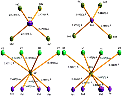 | ||
| Fig. 3 Coordination environments of the Fe and Se sites in K0.862(3)Fe1.563(4)Se2. Fe sites are shown as purple, Se gold, and K green ellipsoids. Ellipsoids are drawn at 50%. | ||
The potassium cations occupy eight coordinate sites within the AAA stacked Fe1.6−ySe2 layers, and are in cubic coordination similar to that in the fluorite structure. There are two distinct sites — K1 on the 2b position with 4/m symmetry is coordinated solely by Se2 and sits between squares of four occupied Fe1 sites. K2 is coordinated by six Se2 and two Se1 anions, the Se1 sites being directly above each other along the c direction, and is located above three Fe1 and one almost vacant Fe2 site. Unlike the two Fe sites, both K sites have very similar occupancies in both refined crystals, consistent with the longer bond lengths at the sites producing less of an energy penalty for vacancy disorder.
The distinction between the two Se sites rumples the surface of the Fe1−xSe layer giving two distinct thicknesses for the chalcogenide layers — a parameter shown to strongly influence Tc in the vacancy-free Fe1+x(Se,Te) systems20,21 — of 3.10 Å (Se1 to Se1 vertical separation along c), 3.02 Å (Se2 to Se1) and 2.94 Å (Se2 to Se2) due to the greater displacement of Se2 from the predominantly vacancy bearing Fe2 site it neighbours. The Se2⋯Se2 distances of 3.989 Å parallel and 4.074 Å perpendicular to the Fe1−xSe plane reflect a strong compression of the Fe2Se4 tetrahedra within the basal ab plane, also seen in the Fe1Se4 units. The Fe1-based tetrahedron has a mean Se–Fe–Se angle of 109(4)° — the distortion is more complex than found in simpler stoichiometric layers as although the two angles bisected by the c axis are on average more compressed (105(3)°) than those bisected by the ab plane (111(2)°) as found in the simpler stoichiometric materials such as FeSe15 and LiFeAs,22 the ab-bisected Se2–Fe1–Se2 angle of 107.32(2)° is smaller than that bisected by c of 107.94(2)°, which is the typical case in the LnOFeAs systems.23 The slab thicknesses discussed above are comparable to those for the undistorted FeSe. The introduction of K into the fluorite-like slabs increases the interlayer separation to between 3.83 Å (Se1⋯Se1 contacts) and 4.00 Å (Se2⋯Se2) from 2.55 Å, which should increase the electronic two-dimensionality of the system. However, as the packing motif of the FeSe layers along c in the two structural types is different, the interlayer Se⋯Se contacts are not affected much (3.75 Å in FeSe).
The refined fractional occupancies of both the Fe1 and Fe2 sites which are respectively full and empty in the ideal Fe1.6Se2 structure corresponding to the observed unit cell suggest that the crystals contain disordered regions. This may be due to the presence of fully disordered regions (11% occupancy of Fe2 corresponds to 15% of a disordered component with 80% occupancy of both sites in crystal 1) or to stacking faults where each layer contains the same vacancy ordering motif but phase coherence is lost in the stacking along c. This is consistent with the observation of extension of the reflections along c* in the observed diffraction patterns (Fig. 1(b)) and suggests an order-disorder transition which could be controlled by annealing or subsolidus routes to these materials.
Conclusions
The presence of two distinct iron sites in the Fe1.6−ySe2 layers suggests selective metal doping will be possible, with mixed anion materials accessible due to the two distinct coordination numbers of the two observed anion sites.The crystals studied here are not superconducting but the role of vacancies in superconducting compositions is clear, and the present structures show how these vacancies can be accommodated. The ordered distribution of vacancies on the Fe sites is required to accommodate the high level of Fe deficiency compared with the FeSe parent material and other families of Fe-based superconductors. The structural motif observed is suited to a 4![[thin space (1/6-em)]](https://www.rsc.org/images/entities/char_2009.gif) :1 occupied:vacancy ratio with an ideal layer composition of Fe1.6Se2. The observed compositions can be thought of as corresponding to K0.8+xFe1.6−x/2S2 to maintain the Fe2+ charge state, with deviations from this relationship permitting electron or hole doping. Higher iron content than 1.6 can be expected to produce alternative, sparser vacancy orderings based on different modulation vectors.11 It is straightforward to envisage a family of materials with related tetrahedral site vacancy orderings allowing tuning of the metal composition within an ordered structure in turn giving different accessible electronic properties. The vacancies on the K sites are in contrast positionally disordered suggesting lower temperature synthesis approaches may allow enhanced control of their distribution with associated impact on the electronic behaviour. The observed compositions and disorder of both refined crystals do not completely fit with the underlying lattices suggesting milder synthesis conditions to obtain the same target compositions may afford better ordered materials.
:1 occupied:vacancy ratio with an ideal layer composition of Fe1.6Se2. The observed compositions can be thought of as corresponding to K0.8+xFe1.6−x/2S2 to maintain the Fe2+ charge state, with deviations from this relationship permitting electron or hole doping. Higher iron content than 1.6 can be expected to produce alternative, sparser vacancy orderings based on different modulation vectors.11 It is straightforward to envisage a family of materials with related tetrahedral site vacancy orderings allowing tuning of the metal composition within an ordered structure in turn giving different accessible electronic properties. The vacancies on the K sites are in contrast positionally disordered suggesting lower temperature synthesis approaches may allow enhanced control of their distribution with associated impact on the electronic behaviour. The observed compositions and disorder of both refined crystals do not completely fit with the underlying lattices suggesting milder synthesis conditions to obtain the same target compositions may afford better ordered materials.
Acknowledgements
We thank EPSRC for support under EP/H000925/1, EP/G037132 and EP/G037949 and STFC for access to the synchrotron X-ray facilities at Diamond Light Source.Notes and references
- Y. Kamihara, T. Watanabe, M. Hirano and H. Hosono, J. Am. Chem. Soc., 2008, 130, 3296 CrossRef CAS.
- F. C. Hsu, J. Y. Luo, K. W. Yeh, T. K. Chen, T. W. Huang, P. M. Wu, Y. C. Lee, Y. L. Huang, Y. Y. Chu, D. C. Yan and M. K. Wu, Proc. Natl. Acad. Sci. U. S. A., 2008, 105, 14262–14264 CrossRef CAS.
- S. Medvedev, T. M. McQueen, I. A. Troyan, T. Palasyuk, M. I. Eremets, R. J. Cava, S. Naghavi, F. Casper, V. Ksenofontov, G. Wortmann and C. Felser, Nat. Mater., 2009, 8, 630–633 CrossRef CAS.
- S. Margadonna, Y. Takabayashi, Y. Ohishi, Y. Mizuguchi, Y. Takano, T. Kagayama, T. Nakagawa, M. Takata and K. Prassides, Phys. Rev. B: Condens. Matter Mater. Phys., 2009, 80, 064506 CrossRef.
- X. H. Chen, T. Wu, G. Wu, R. H. Liu, H. Chen and D. F. Fang, Nature, 2008, 453, 761–762 CrossRef CAS.
- Z. A. Ren, W. Lu, J. Yang, W. Yi, X. L. Shen, Z. C. Li, G. C. Che, X. L. Dong, L. L. Sun, F. Zhou and Z. X. Zhao, Chin. Phys. Lett., 2008, 25, 2215–2216 CrossRef.
- J. Guo, S. Jin, G. Wang, S. Wang, K. Zhu, T. Zhou, M. He and X. Chen, Phys. Rev. B: Condens. Matter Mater. Phys., 2010, 82, 180520 CrossRef.
- A. Krzton-Maziopa, Z. Shermadini, E. Pomjakushina, V. Pomjakushin, M. Bendele, A. Amato, R. Khasanov, H. Luetkens and K. Conder, arXiv, 2011, 1012.3637.
- Y. Mizuguchi, H. Takeya, Y. Kawasaki, T. Ozaki, S. Tsuda, T. Yamaguchi and Y. Takano, Appl. Phys. Lett., 2011, 98, 042511 CrossRef.
- P. Zavalij, W. Bao, X. F. Wang, J. J. Ying, X. H. Chen, D. M. Wang, J. B. He, X. Q. Wang, G. F. Chen, P.-Y. Hsieh, Q. Huang and M. A. Green, arXiv, 2011, 1101.4882.
- Z. Wang, Y. J. Song, H. L. Shi, Z. W. Wang, Z. Chen, H. F. Tian, G. F. Chen, J. G. Guo, H. X. Yang and J. Q. Li, arXiv, 2011, 1101.2059.
- T. M. McQueen, Q. Huang, V. Ksenofontov, C. Felser, Q. Xu, H. Zandbergen, Y. S. Hor, J. Allred, A. J. Williams, D. Qu, J. Checkelsky, N. P. Ong and R. J. Cava, Phys. Rev. B: Condens. Matter Mater. Phys., 2009, 79, 014522 CrossRef.
- V. Petricek, M. Dusek and L. Palatinus, Institute of Physics, Praha, Czech Republic, 2006.
- L. Palatinus and G. Chapuis, J. Appl. Crystallogr., 2007, 40, 786–790 CrossRef CAS.
- S. Margadonna, Y. Takabayashi, M. T. McDonald, K. Kasperkiewicz, Y. Mizuguchi, Y. Takano, A. N. Fitch, E. Suard and K. Prassides, Chem. Commun., 2008, 5607–5609 RSC.
- F. Q. Huang and J. A. Ibers, Inorg. Chem., 2001, 40, 2602–2607 CrossRef CAS.
- M. Zabel and K. J. Range, Rev. Chimie Min., 1980, 17, 561–568 Search PubMed.
- S. J. Clarke, P. Adamson, S. J. C. Herkelrath, O. J. Rutt, D. R. Parker, M. J. Pitcher and C. F. Smura, Inorg. Chem., 2008, 47, 8473–8486 CrossRef CAS.
- L. Haggstrom, H. R. Verma, S. Bjarman, R. Wappling and R. Berger, J. Solid State Chem., 1986, 63, 401–408 CrossRef.
- K. Kuroki, H. Usui, S. Onari, R. Arita and H. Aoki, Phys. Rev. B: Condens. Matter Mater. Phys., 2009, 79, 224511 CrossRef.
- Y. Mizuguchi and Y. Takano, J. Phys. Soc. Jpn., 2010, 79, 102001 CrossRef.
- M. J. Pitcher, D. R. Parker, P. Adamson, S. J. C. Herkelrath, A. T. Boothroyd, R. M. Ibberson, M. Brunelli and S. J. Clarke, Chem. Commun., 2008, 5918–5920 RSC.
- C. H. Lee, A. Iyo, H. Eisaki, H. Kito, M. Teresa, F. Diaz, T. Ito, K. Kiho, H. Matsuhata, M. Braden and K. Yamada, J. Phys. Soc. Jpn., 2008, 77, 083704 CrossRef.
Footnote |
| † CCDC reference numbers 811549–811550. For crystallographic data in CIF or other electronic format see DOI: 10.1039/c1sc00070e |
| This journal is © The Royal Society of Chemistry 2011 |